
Abstract
Wedge shaped combined plate structure (WCPS) is broadly applied in large-sized transport equipment such as aerospace and shipping. However, with the increase of equipment operating running, it is easy to cause high-frequency vibration of structure components. Therefore, studying the energy transfer and vibration response of high-frequency vibration in WCPS is significant for the structural design of aerospace and shipping. The promising method is energy finite element analysis (EFEA). However, the energy transfer coefficient at joint of WCPS is needed in EFEA. The current studies about the energy transfer coefficients are focus on the joint between two uniform thickness plate. But it is some different that getting the energy transfer coefficient for WCPS, because the near-field solve representation for wedge-shaped plate is complicated due to the non-uniform thickness of wedge-shaped plate member in WCPS. In this research, geometric acoustic approximation and an equilibrium equation on both ends of joints were used to derive the equation of the energy transfer coefficient for the WCPS. Then by setting coupling nodes, construction of a coupling matrix to characterize discontinuity of energy density at the coupling position of the WCPS and energy density governing equation of wedge-shaped plates were integrated. In doing so, the EFEA modeling of the WCPS was developed and the energy density distribution on each node of the WCPS could be obtained. Same-sized uniformly coupled structures is analyzed, the vibration energy distribution characteristics of two types of coupling structures were compared. The results show that the energy density value of the wedge plate member attenuate more slowly than that of the uniform plate member due to the acoustic black hole aggregation effect in the wedge plate part, and there is an abrupt change in the energy density value at the joint of WCPS. As a result, the factors influencing high-frequency vibration energy transfer were investigated.
Keywords
Introduction
The WCPS is composed of uniform thickness plate member and wedge-shaped plate member, which is a common type of coupled structure. Due to the inhomogeneity of thickness, the WCPS in the structural design can be flexibly designed according to loading conditions and lightweight design requirements. Therefore, the WCPS is broadly applied in large-sized transport equipment such as aerospace and shipping. However, with the rise of running speed, the transport equipment is mostly triggered high-frequency vibration. Research of high-frequency vibration characteristics is a key step of structural design for high-speed transport equipment.
Many scholars investigated the vibration characteristics of the coupled structure. Aiming at the coupled plate structure having special boundary conditions, Wang et al. 1 promoted the application of a structural finite element equation for dynamic response analysis in the theoretical calculations of plate-shell vibration power flow. Furthermore, they analyzed the energy transfer characteristics of structural vibrations of the coupled plate. Yang et al. 2 used the finite element method (FEM) and structure modal analysis method to build a FEM model of shaft-shell coupled structure and substructure coupled model, to analyze vibration characteristics of this coupled system under the friction excitation. Ma et al. 3 studied vibration characteristics of cone-cylindrical shaped shells and obtained the forced vibration characteristics of the shells under point loads. Shi et al. 4 explored the dynamic characteristics of a cylindrical shell-annular plate coupled structure using a spectral geometry method and verified the validity of the analysis model using the FEM. Qin et al. 5 studied the vibration waves of a hull-plate coupled structure, which provided a mathematical model for vibration analysis of cylindrical shells-annular plate coupled structure and verified the correctness of this model. Ghorbanpour Arani6–8 conducted theoretical research on the vibration characteristics of different coupled sandwich panels, providing guidance for military, aerospace, and other fields. The studies aforementioned analyzed vibration responses of coupled structures using the FEM, modal analysis method, etc. However, for high-frequency vibration problems, the vibration modal density is dense, and is likely to generate local vibration responses. It is not easy to calculate such dense vibration modal and fails to accurately predict local responses by using FEM.
The EFEA based on the theory of wave motion takes the average energy density from the temporal-spatial perspectives as the variable of the governing differential equation. Then, it utilizes the idea of the FEM to solve this governing differential equation to obtain the energy density of all nodes inside the structures to be studied. The EFEA is a promising method for high-frequency vibration problems. In previous work, Xie et al. has developed the EFEA model for wedge-shaped beams to predict the vibration energy distribution of wedge-shaped beams under high-frequency excitation. 9 Ghorbanpour Arani et al. has conducted extensive research on the propagation of coupled structural vibration waves, providing a reference for the subsequent solution of motion equations and derivation of energy density governing equations in this paper.10–12
When solving issues is about combined structures using the EFEA, the energy density at coupling joints is discontinues. It is thus necessary to research the energy transfer coefficient at the joints, to reflect the energy transfer relationship to the total stiffness matrix. This demonstrates the difference of the EFEA and FEM when solving issues related to combined structure. Cho and Bernhard 13 for the first time proposed the use of the EFEA in combined structure. They innovatively used virtual elements of coupling joints, namely, a node contacted by the two structures at the coupled position is disassembled into two nodes. This effectively solved the issues arising from energy density discontinuity at coupling joints in the numerical solution process. Niu and Li 14 analyzed the energy flow and energy density distribution of N-shaped plates coupled at arbitrary angles considering the three waves inside the plate. Jiang 15 segmented grids of arbitrary plates using triangular elements to acquire the energy density distribution and energy flow distribution of arbitrary plates and their combined structures. Liu et al. 16 utilized the EFEA to perform dynamic analysis of multi-plate combined structures. On this basis, the energy transfer coefficient of the coupling position and global finite element equation of multi-plate structures were obtained. The constructed model was able to simultaneously forecast the energy density distribution of in-plane waves and flexural waves of multi-plate structures. The combined structures of studies aforementioned are all structures which connected between uniform-thickness plates and uniform-thickness plates. But it is different that getting the energy transfer coefficient for WCPS, because the near-field solve representation for wedge-shaped plate is complicated due to the non-uniform thickness of wedge-shaped plate member in WCPS.
In this research, an EFEA model for WCPS was established. According to the equilibrium equation on both ends of coupling joints, the coupling matrix at the coupling joint was built based on the energy transfer coefficient. Integrating the coupling matrix with the energy density governing equation of the wedge-shaped plate, the EFEA of the combined wedge-shaped structure could be obtained to analyze the WCPS. In doing so, the energy density distribution of the WCPS was determined and uniform-thickness plates were comparatively analyzed.
The EFEA model for the WCPS
The energy density governing equation for wedge-shaped plates
According to the Equation of motion of wedge-shaped plates and the energy-balance relationship, the energy density governing equation of the wedge-shaped plate structure can be derived 17 :

Where
For complex structure, the Galerkin weighted residual method can be used to solve numerical solution of energy density governing equation (1) in terms of weighted integral. 19 Finally, the weak variational formulation of the equation can be simplified into:
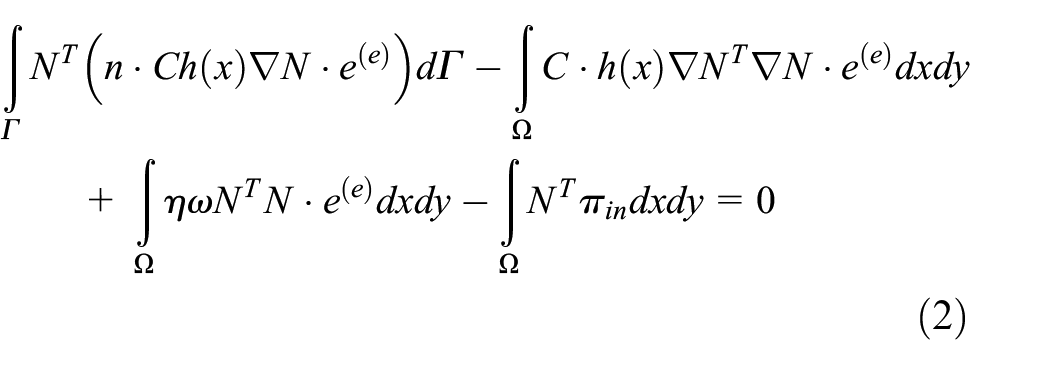
Where
Equation (2) is written as the form of the matrix equation as follows:

Where:


The energy transfer relationship of coupling joints for the WCPS
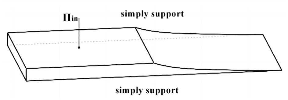
Elastic waves in the WCPS will generate reflection and transmission at the coupling position. Among which, the energy transfer coefficient of the combined structure is a key calculation issue. The WCPS structure of this research is illustrated in Figure 1. Through analyzing the energy transfer relationship of the WCPS, the energy transmission and reflection at the coupling joints can be solved. For uniform-thickness plate member, semi-infinite plate can approximately replace the finite plate member.

The schematic diagram of the WCPS.
Assuming that uniform-thickness plate member and wedge-shaped plate member connect at the position of


Where
The governing equation of flexural wave inside the uniform-thickness plate member can be described 25 :

Where


Where
For the uniform-thickness plate member, equation (5) can be decomposed into:


Based on the governing equation of flexural wave in the uniform-thickness plates, the incident flexural wave with a wave amplitude of

The lateral displacement generated in this incident wave can be described as 25 :

Substituting equation (10) respectively into equations (7) and (8) yields:


In the deriving process of the energy density governing equation of wedge-shaped plates, lateral displacement wave solution only considers far-field items, however in the combined plate structure as shown in Figure 1, the presence of coupling joints makes the neglect of near-field waves existing in the plate structure impossible. For the uniform-thickness plate member, the lateral displacement of flexural waves of near-field items along the

Where
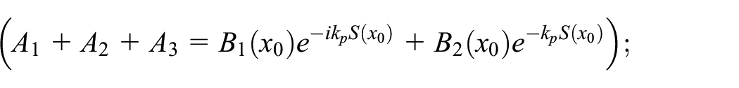
The incident flexural wave passing through coupling joints will transmit and generate the far-field and near-field waves along the forward transmission. Hence, based on the geometric acoustic approximation, the lateral displacement of flexural waves in member of flexural wave in the wedge-shaped plate member is expressed as23,24:

Substituting this condition into equation (14) gets:

Likewise, the unknown complex wave amplitude of the WCPS is determined by the equations for continuity conditions for the displacement and rotation angle and the equilibrium condition of bending moment and shear force in the position of coupling joints:


The bending moment
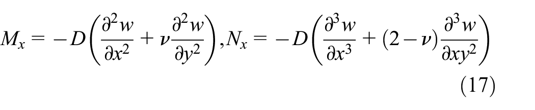
Substituting equations (13) and (15) into the equilibrium condition (16) yields:


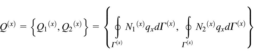
Through solving the equation set (18), the relationships among

According to the law of conservation of energy, the mean incident power of flexural waves is the sum of the average values of wave transmission and reflection powers, thus:

Substituting the time averaged value of each elastic wave power into the above equation, the energy reflection coefficient and transmission coefficient of the WCPS can be obtained:

Where bending stiffness


The equation aforementioned is same to the equations of the energy transmission coefficient and reflection coefficient of structures combined with two uniform-thickness plates in literature, 25 namely, the energy transfer coefficient equation of the structures combined with two uniform-thickness coupling plates is a special case of the energy transfer coefficient of the WCPS. This proves the correctness of the derivation of the energy transfer coefficient of the wedge-shaped coupling plate, and to some extent, it can also demonstrate that the energy transfer coefficient of the wedge-shaped coupling plate is more universal and can be used as a reference in similar work in the future.
The total stiffness matrix of the WCPS
For the two-dimensional structure, the element stiffness matrix at the coupling joints requires to be established on the intersecting line of coupling interfaces. Its energy density governing matrix can be written as:
Where


Equation (24) adopts the modeling of two four-node quadrilateral elements on the combined plate model aforementioned. As the two-dimensional boundary element is a line, the energy flow of elements at the coupling joints was interpolated using linear Lagrange. Because there are only two nodes set at the boundary, the interpolation function of Lagrange n = 2, the sigmoid function
Also at the coupling positions, the flexural wave that shows the forward transmission along the coordinate (referring to the energy flow of the coupling points) can be defined “+”, similarly, the flexural wave having reverse transmission (representing the energy density far away from the coupling point) can be defined “−”. Considering the reflection and transmission of waves simultaneously occur in the position where the coupling boundary is located, we get:


The energy flow of coupling joints at the position where the coupling boundary is located is energy flow difference in positive and negative directions, we obtain:


Rewriting the above equation into the equation in a matrix form:

Also, due to

According to the matrix equation aforementioned, the relationship between energy flow and energy density can be obtained:

Where

Integrating the matrix equation (29), then:

Where
The coupling matrix of the coupling position can be obtained:
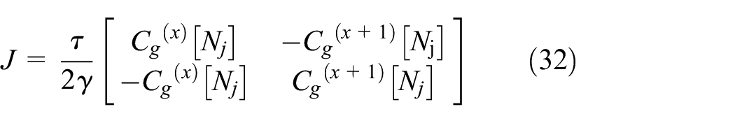
Substituting the coupling matrix into the stiffness matrix yields the overall matrix of the WCPS:

By solving the matrix equation aforementioned, the energy density distribution of the WCPS can be determined.
The vibration energy distribution and influencing factors of the WCPS
This section takes a combined wedge-shaped flat plate consisting of the uniform-thickness plate and the wedge-shaped plate as a research object. This wedge-shaped plate combination dimension is 2 m × 1.2 m, among which, the uniform-thickness flat plate measures 1 m × 1.2 m. The law of thickness changes in the wedge-shaped plate member meets

The grid model of the WCPS.
Material parameters of the wedge-shaped plate include: Young’s modulus E = 9.6 × 10¹⁰ Pa, Poisson’s ratio υ = 0.35, the damping coefficient η = 0.02, and the plate density ρ = 4.62 × 10³ kg/m3. The 33th node of the WCPS is subjected to a load of 1 × 10⁻³ W in the direction of the lower surface for the vertical plate structure and the excitation frequency f = 1000 Hz. The excitation position is shown in Figure 3.
The WCPS subjected to the point excitation
Model validation
In order to verify the correctness of the model proposed in this paper, finite element analysis was applied to predict the energy density of WCPS with the same structure. The material properties, and size are as mentioned above, and a cross-sectional thickness ratio of H2/H1 = 1. Excitation was applied at the same position with an excitation frequency of 1000 Hz. The energy density distribution results of EFEA and FEA at y = 0.6 were compared, as shown in Figure 4. Due to the significant influence of the number of grids and modes on the FEA results, there is a small difference between the two. However, the trend and magnitude of the results calculated by EFEA and FEA are relatively consistent. It is proved that the energy finite element model for WCPS is accurate and reliable in this paper.

Energy density distribution results of EFEA and FEA at y = 0.6.
Additionally, the EFEA results with respect to the number of elements is investigated. Under the same conditions of material parameters and excitation methods, the WCPS is divided by 8, 60, 240 elements respectively. The results about different numbers of element is as shown in Figure 5. The results show that the response trends corresponding to the number of elements are basically consistent, and there is a slight difference in numerical results. It is consistent with the viewpoint in Lin. 26

The influence of different number of elements on response results.
The vibration energy distribution of the WCPS
According to the finite element model of the WCPS, the energy density value of different nodes on the WCPS can be calculated. To observe the energy density values of different nodes on the WCPS and the energy density change at the coupling joints, the element abscissas of the wedge-shaped plates are all subjected to an offset of one element length to the right. By logarithmizing the energy density value, the energy density distribution nephogram of various nodes on the WCPS under the excitation frequency of f = 1000 Hz is illustrated in Figure 6. The simply supports on both ends (y = 0 and y = 1.2 m) of the WCPS is made, no vibration being found in the z axis direction. Hence, the energy density of nodes on the simple support boundary for the wedge-shaped plate is 0. For the sake of observations of results, Figure 7 shows the energy density distribution 3D nephogram without considering the boundary node.
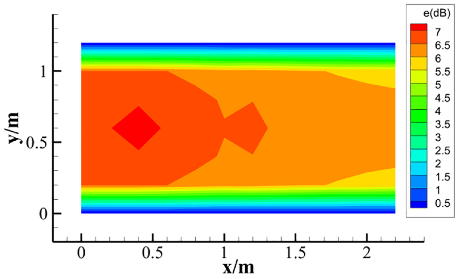
The energy density distribution nephogram of WCPS.

The energy density distribution nephogram without the boundary nodes.
As illustrated in Figure 6, the energy density value at the excitation position on the wedge-shaped plate member maximizes and it presents attenuation to all directions along the excitation position, and sudden changes when passing through coupling joints. In the case of y = 0.6 m, the same length interval at the wedge-shaped plate member and uniform-thickness plate member is taken respectively. Setting the length intervals of the wedge-shaped plate member from x = 0.4 m to x = 1 m and the length intervals of the uniform-thickness plate member from x = 1.6 m to x = 2.2 m, the attenuation speed of energy density on uniform-thickness plates is far greater than that of wedge-shaped plates.
As presented in Figure 7, the energy density undergoes sudden change at the coupling joint, its value of the wedge-shaped plate at the coupling joints is higher than that of uniform-thickness plate. The energy density value at the position where excitation is applied is maximum. Due to the damping effect, the energy density gradually attenuates with the increasing distance away from the excitation position. Energy density passes through the coupling joint to be further transferred to the wedge-shaped plate, but it still maintains such declining trend. The slope of the energy density change in the uniform-thickness plate is steeper, however, the slope of the energy density change in the wedge-shaped plate is gentler. Hence, the phenomenon can be intuitively observed. that in the wedge-shaped plate the energy density attenuation trend is gradually slow.
Along the thickness varying direction, the wedge-shaped plate presents the Acoustic Black Hole effect based on the thickness of the power-law cutting board, which reduces the attenuation speed of the energy density. To further the Acoustic Black Hole effect of the wedge-shaped plate, the rectangular uniform-thickness plate is taken an example measuring 2 m × 1.2 m, with a thickness of 0.01 m. The other material parameters and boundary conditions are consistent with that of the WCPS. Due to the absence of coupling joints, this rectangular plate grid comprises 60 four-node elements and 77 nodes. The energy density distribution nephogram of different nodes for the rectangular plate under the excitation of flexural wave when the excitation frequency is calculated to be f = 1000 Hz.
Comparison of Figures 6 and 8 shows that compared with the WCPS, rectangular plates due to the absence of coupling show no energy reflection and transmission. Thus, at x = 1 m, no sudden changes occur to the energy density. Owing to the effect of structural damping on energy dissipation, the energy density at the excitation position maximizes. The further from the excitation position, the energy density continues to attenuate. Compared to the results of the WCPS (Figure 6), when y = 0.6 m, the energy density transmits along the x direction with a distance same as wedge-shaped plates. The attenuation speed of uniform-thickness plates is faster. This is due to the acoustic black hole energy gathering effect of the wedge-shaped plate in the WCPS structure, which effectively improves the dissipation and transfer efficiency of vibration energy.
The energy density distribution nephogram of the rectangular plate.
Influences of the cross-section thickness of wedge-shaped plates on response results
Based on equation (21) and the equation of bending stiffness D, changes in the cross-section thickness of the coupling position can influence the coupling coefficient, which further affects the coupling matrix. Therefore, it is necessary to discuss influences of the cross-section thickness on the vibration of WCPS. In this section, influences of different ratios of the cross-section thickness H2 of wedge-shaped plates to the cross-section thickness H1 of uniform-thickness plates on the energy density distribution of the WCPS were calculated. In this numerical example, except for changes in the thickness of some sections of the wedge-shaped plate member, other parameters coincide with Section “Model validation.” It can be found that when the wedge-shaped plates demonstrate different cross-section thicknesses, the energy density distribution 3D nephograms of the WCPS without considering joint nodes are presented in Figure 9. To conveniently observe the energy flow of the WCPS, the element abscissas of the wedge-shaped plates are all subjected to an offset of one element length to the right, as shown in Figure 10.

The energy density distribution nephograms.

The energy density distribution nephograms subjected to the offset.
Observations of the energy density distribution nephograms of WCPS at different cross section thickness ratios (H2/H1) as shown in Figure 10 show that when other parameters are unchanged, the energy density values of flexural waves inside wedged-shaped plates decrease with increasing cross section thickness ratios (H2/H1). The energy density of Coupling joints 42 and 43 is displayed in Table 1. For the sake of observations, the energy density of the coupling position at four H2/H1 values when y = 0.6 m was plotted at a same coordinate system, as shown in Figure 11.
Energy density of different cross section thickness ratios.


The energy density distribution of WCPS at the coupling position in the case of different cross section thickness ratios (H2/H1).
The calculated results indicate that the larger the cross section thickness ratio, the more obvious the sudden change in the energy density at the coupling position, which can be used for comparing sudden changes in energy density at the coupling position at different cross section thickness ratios. The reason for this phenomenon is that the change in cross-sectional ratio will cause a change in the connection matrix through the energy transmission coefficient and reflection coefficient. As the thickness ratio increases, the distribution difference of energy density between the two boards will gradually increase.
Influences of material parameters on response results
According to the transmission coefficient equation, the material parameters exert important influences on the vibration of the WCPS. Numerical example in this section calculates influences of wedged-shaped plates made from different materials on the transmission coefficient to further derive their influences on the energy density distribution of the coupling position. The material parameters used in this numerical example are shown in Table 2.
Material parameters.
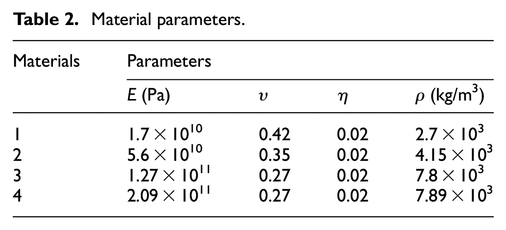
The materials of wedge-shaped plates were set to Material 1, Material 2, Material 3, and Material 4. The material of uniform plates is original material. The calculated parameters of different materials are listed in Table 3.
Parameters of different materials.

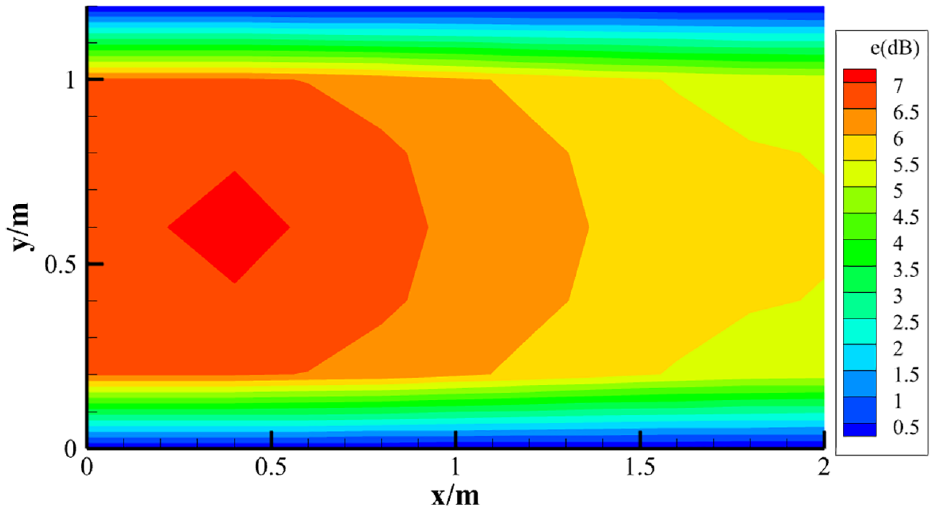
The bending stiffness D1 of uniform plates is 9116.8 N/m. For the sake of observations, the materials can be categorized into two types for display according to the value of bending stiffness: the stiffness of the first type of wedge-shaped plates is smaller than uniform plates; the stiffness of the second type of wedge-shaped plates is larger than uniform plates. The energy density distribution of two types of coupling structures at y = 0.6 m is shown in Figures 12 and 13.

The energy density distribution when materials of wedge-shaped plates are 1 and 2.

The energy density distribution when materials of wedge-shaped plates are 3 and 4.
As shown in Figures 12 and 13, the material parameters have influence on the transfer of vibration waves. The difference in materials can directly influence the value of the transmission coefficient. When the bending stiffness of the material for wedge-shaped plates is smaller than that of uniform plates, the larger bending stiffness D2 of wedged plates, the larger the transmission coefficient, the smaller the energy density difference at coupling joints; meanwhile, the energy density value after sudden change is bigger than that of before sudden change; when the bending stiffness of the material for wedge-shaped plates is larger than that of uniform plates. The larger bending stiffness D2 of wedged plates, the greater the transmission coefficient, the larger the energy density difference at coupling joints. The energy density value after sudden change is less than that of before sudden change, which conforms to the derived transmission coefficient equation. Meanwhile, material has an important influence on the vibration wave transfer of the WCPS.
Conclusion
The energy transfer coefficient for WCPS is obtained, and the EFEA model for the WCPS is developed. Then the factors influencing high-frequency vibration energy transfer is investigated. The model helps to use EFEA to predict the high frequency dynamic response in WCPS.
The conclusions includes as follows:
Through comparison, it was found that the energy transfer coefficient expression for structures combined with two uniform plates is a special case of the energy transfer coefficient expression for WCPS, proving the reliability and rationality of the EFEA model in this paper.
In WCPS, the energy density will suddenly change at the coupling joint. If the section thickness ratio is H2/H1 = 1.5, the difference in energy density between the representative nodes of two side of joint is 0.0011 dB. If the section thickness ratio is H2/H1 = 3, the difference of energy density between the two nodes is 0.3661 dB. The reason is that as the section thickness ratio increases, the obstruction effect of structural coupling on vibration waves will be weakened, and the transmittance coefficient will increase accordingly, making the sudden change in energy density more obvious. The differences in material properties can also lead to differences in transmission coefficients, indicating that materials have an important impact on the transmission of vibration waves in wedge-shaped coupled plate structures.
The EFEA model for WCPS obtained in this paper does not require a high number of grids and has a faster calculation speed, compared to FEA. EFEA model for WCPS can promote the application of EFEA and SEA in variable thickness composite structures. However, the structure studied in this paper is only suitable for damping coefficients η << 1 and specified variable thickness plate. The EFEA model for more common WCPS is required in the future research to predict more general engineering problems.
Footnotes
Handling Editor: Dr Sharmili Pandian
Declaration of conflicting interests
The author(s) declared no potential conflicts of interest with respect to the research, authorship, and/or publication of this article.
Funding
The author(s) disclosed receipt of the following financial support for the research, authorship, and/or publication of this article: This work was supported by NSFC (51305330) and the Natural Science Foundation of Shaanxi Province, China Grant (No. 2024JC-YBMS-370) and Shaanxi Province Qinchuangyuan “Scientists + Engineers” Team Construction Grant (No. 2022KXJ032).