
Abstract
With the improvement of the reliability and lifespan of electrical connectors, the traditional single objective design focusing solely on performance or reliability has become inadequate to meet the requirements. This paper analyzes the failure mechanism of a specific electrical connector under the conditions of insertions-extractions. It establishes a contact degradation model and an integrated design model that considers mechanical properties and reliability. By analyzing the integrated design model, the optimization variables have been defined as the radius of the spring wire, the radius of the pin, the inner radius of the inner sleeve, the length of the inner sleeve, and the inclination of the spring wire. Additionally, the objective function of optimization has been determined. The optimal solutions that satisfy the constraints were calculated using the global optimization algorithm. The optimization results not only achieve the goal of high reliability but also the goal of extended mechanical life.
Keywords
Introduction
Spring-wire socket electrical connectors are widely used in military and civilian applications. Among various types of electrical connectors, spring-wire socket electrical connectors are increasingly being utilized due to their high contact reliability, superior performance, and resistance to harsh environments. Long mechanical life and high reliability are required for electrical connectors during long-term storage. For example, a system specifies that when the storage life reaches 32 years, the contact reliability should reach 99.9%, and the number of insertions-extractions (i.e. Mechanical properties) must reach 1000 times. 1 Currently, electrical connectors are typically designed with a single design goal, such as performance or reliability, and cannot meet the requirements of both performance and reliability. In order to solve this problem, it is necessary to integrate the performance and reliability design of spring-wire socket electrical connectors.
Liu et al. 2 explained the concept of integrated design in detail and expanded the research field of integrated design by combining the product life cycle, performance parameters, and multidisciplinary characteristics. Based on Liu’s theory, Li et al. 3 proposed an integrated design method of testability and performance. The above research provides a theoretical basis for integrated design but does not include product reliability as its design goal and has not been applied to any specific field. Chen et al. 4 proposed a design method for the integration of control performance and reliability by taking the flight control system as an example and established a design model for the integration of control performance and reliability. Liu et al. 5 proposed an integrated design approach for electrical performance and reliability using integrated circuits as an example. The above study only discusses product performance and reliability side by side and does not consider the impact of performance on reliability. For electrical connectors mechanical performance affects reliability, that is, as the number of insertions-extractions increases, the reliability of the product decreases. Wang et al. 6 established a reliability model of electrical connectors combining micro variables and macro variables based on oxidation reaction. Kang et al. 7 proposed the basic process of reliability optimization design for spring-wire socket electrical connectors based on the reliability forward design optimization method. Luo et al. 8 proposed a method for detecting the insertions-extractions wear of electrical connectors. The wear distribution of electrical connector contacts is detected by this method. Li 9 designed an electrical connector suitable for underwater environment by analyzing the working characteristics and performance requirements in such conditions. The above studies only design electrical connectors from a single level, such as reliability or performance, and do not consider the multi-objective requirements of performance and reliability. In solving integration optimization problems, global algorithms 10 and swarm algorithms 11 are widely used because of their global nature, high speed, and other advantages. However, the paper focuses on integrated modeling of the performance and reliability of electrical connectors and optimization design based on the integrated model.
This paper applies the integrated design method to the design process of electrical connectors, establishes a contact resistance degradation model and an integrated design model combining the performance and reliability of spring-wire socket electrical connectors, and based on this model, the global optimization algorithm is used to find out the optimal solution to meet the constraints to achieve the integrated design of spring-wire socket electrical connectors in terms of performance and reliability. It provides a method for the multi-objective optimization design of the same type of connector.
Failure mechanism analysis of spring-wire socket electrical connector
Structural and functional requirements of electrical connector
The electrical connector contact is composed of a pin, spring-wire, inner sleeve, front sleeve, and rear sleeve, as shown in Figure 1. The inner sleeve is used to support the spring-wire. The front sleeve is used to fix the inner sleeve. The pin is made of tin bronze with gold plating, while the spring-wire is made of beryllium bronze with gold plating. Gold has high chemical stability, and the gilt layer can reduce the oxidation of copper.
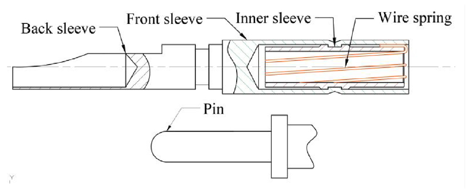
Contact structure schematic diagram.
The spring-wire rotates around the centerline at a specific angle to form a spring-wire socket, and the ends of the spring-wire socket are fixed in the inner sleeve, as shown in Figure 1. The pin and the spring-wire socket form the contact pair. The smallest circle of the spring-wire socket is defined as the throat circle, and it is situated at the center of the spring-wire socket. The center circle at the ends of the spring-wire socket is called the end circle. The diameter of the pin is larger than the diameter of the throat circle and smaller than the diameter of the end circle. During the insertion process, the spring-wire undergoes elastic deformation, ensuring stable contact between the pin and the spring-wire socket. The single spring-wire is shown in Figure 2. In the diagram,

Schematic diagram of a single spring-wire inserted into the inner sleeve.
Taking a specific spring-wire socket electrical connector as an example, it is required to have a mechanical performance capable of withstanding 1000 insertions-extractions. The initial size and material are presented in Table 1.
Contact design parameters and mechanical performance requirements.

Contact failure mechanism of spring-wire socket electrical connector
During extended storage, the contact performance of the spring-wire socket electrical connector will gradually deteriorate due to various environmental stresses. When the contact resistance of the contact pair exceeds the threshold specified in GJB599A-93, it is considered a contact failure. There are two reasons for the failure to make contact.
Oxidation of Copper Alloys. The gold plating on the contact pair is constrained by cost and process limitations, resulting in a thin gold layer, typically 1.27 μm.
1
Consequently, there are inevitably micropores on the surface, and moisture will enter the micropores to form a primary cell. As a result, low-potential copper
The contact pressure decreases. Under prolonged contact pressure, the spring-wire will undergo creep, leading to poor contact and increased contact resistance. 13 However, some data show that the creep of beryllium bronze is only 20.7 μm6 stored for 32 years under the condition of 125°C. Since the creep rate decreases exponentially with temperature, 14 the creep is minimal at the storage temperature of 20°C, and it also has a negligible effect on the contact resistance. The effect of creep can be disregarded.
The influence of insertions-extractions on contact performance
During storage, the spring-wire socket electrical connector needs to be regularly tested and inspected. Therefore, under conditions of frequent insertions-extractions, the gold layer on the contact pair will gradually wear away, leading to an increase in the size of the micropores. Increased moisture will penetrate the micropores, hastening the oxidative corrosion of copper. Insertions-extractions accelerate the growth of contact resistance.
Integrated contact design model considering insertions-extractions effect
Force model of spring-wire
The spring-wire is divided into a contact area and a non-contact area based on the contact state when the pin and the spring-wire socket are fully inserted, as shown in Figure 3. Here
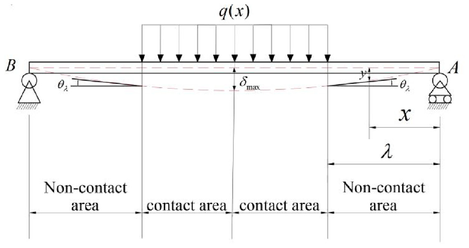
Reference diagram of deformation of spring wire.
According to the geometric relationship in Figure 2 Schematic diagram of a single spring-wire inserted into the inner sleeve, the radius of the end circle, the length of the inner sleeve, and the radius of the throat circle are:


It can be seen from Figures 2 and 3 that when the pin and the spring-wire socket are fully inserted, the maximum deflection of the spring-wire is located at the midpoint, and its magnitude is:

According to the force condition of the spring-wire, it can be simplified as a simply supported beam force model, therefore, the force of the spring-wire is symmetrical, and the force analysis of the half area of the spring-wire is carried out.
It can be seen from Figure 3 that when the pin is in contact with the spring-wire at angle

When the pin is fully inserted with the spring-wire, the spring-wire in the contact area closely attaches to the pin, forming a circular arc. The radius of the circular arc is

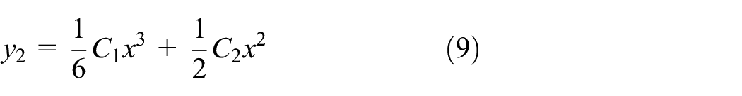
According to the binomial expansion theorem, and by ignoring the high-order term, the deflection curve

Let

According to the characteristics of a simply supported beam, the deflection and torsion angle at the endpoint are both 0. At the critical position
Where
Bending and axial deformation (tensile deformation) of the spring-wire occur when the pin is fully inserted. The contact pressure between the pin and the spring-wire is divided into two parts: the first is the contact positive pressure

Where
The spring-wire and the pin make surface contact. It can be observed from Feng and Gao
16
that the contact surface of the two smooth cylinders forms an ellipse. According to Hertz contact theory,
17
the actual contact pressure

Contact degradation model of spring-wire socket electrical connector under storage conditions
The pin and the spring-wire contact with each other due to the elastic force. Microscopically, a series of raised spots make contact with each other between the pin and the spring-wire.
19
Due to the contact spot is very small, the current flowing through the contact spot will shrink, forming a shrinkage resistance. Meanwhile, there is an oxide film layer on the contact spot, the current through the film, resulting in film resistance. Thus, the contact resistance is divided into three parts: the inherent resistance of the material itself

According to the shrinkage resistance formula and the film resistance formula in the electrical contact theory, 20 it can be observed that:


Therefore, the expression of the contact resistance is:


Wang et al.
6
deduced that the relationship between the average tunnel resistivity

Ping et al.
21
evaluated the value of
Integrated degradation model considering insertions-extractions effect
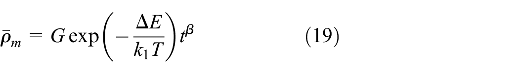
After multiple insertions-extractions, the contact resistance will be increased. Define

According to the analysis, the wear of the gilt layer caused by insertions-extractions accelerates the oxidation corrosion of copper, leading to an increase in film resistance. The increase in film resistance is proportional to the amount of wear. Define

Equation (22) can be simplified as:

Based on the friction energy wear calculation principle,
22
the wear of the gilt layer is proportional to the contact pressure, the number of insertions-extractions

Considering that no insertions-extractions, the increment of film resistance is 0, therefore

Let

Therefore, the integrated degradation model that considers the effects of insertions-extractions is:
Due to the inevitable variations in the machining process and the random nature of the contact state of different contact pairs,
Parameter estimation of integrated degradation model
To determine the parameters in the integrated degradation model, the insertions-extractions test of the contact pairs is carried out. According to the relevant test standards, 23 it can be seen that the number of test samples need to be greater than 5, but in order to ensure the accuracy of the test, 10 contacts were selected as the test object.
In order to ensure the credibility of the test data, the samples of this test are randomly selected, and the 10 groups of samples are completed under the same test conditions and the same test operation, while ensuring that the test temperature is at a constant 20°C. First record the initial value of the contact resistance, then the contact resistance was recorded after 100 insertion-extraction cycles. For ease of calculation and to account for the speed of the oxidation reaction, the interval time between every 100 insertions-extractions was 240 h. Compared to the 32-year storage time and 240-h interval time of the contact parts, the time required for 100 insertions-extractions was very short. Therefore, the time required for 100 insertions-extractions was disregarded, and the initial time for each set of 100 insertions-extractions was used for the calculation. The test was stopped after the number of insertions-extractions reached 1000. To mitigate testing errors, the Kelvin four-wire method was employed to measure the contact resistance, the contact resistance was the average of three measurements. The PZ114 DC digital voltmeter (with a reading accuracy of 0.001 mV and an error of ±0.3%), PA15A DC digital ammeter (with a reading accuracy of 0.0001 A, error of ±0.3%), and a DC power supply were used as test instruments, as shown in Figure 4, to ensure the accuracy of the contact resistance values, 10 sets of contacts were placed on an insulating plate and the ends were secured with adhesive tape. The insertion tester shown in Figure 5 was utilized to maintain the coaxial alignment of the pin and the spring-wire socket, ensuring the stability of the relative slip and contact pressure. The data is shown in Figure 6.

Contact resistance test procedure.
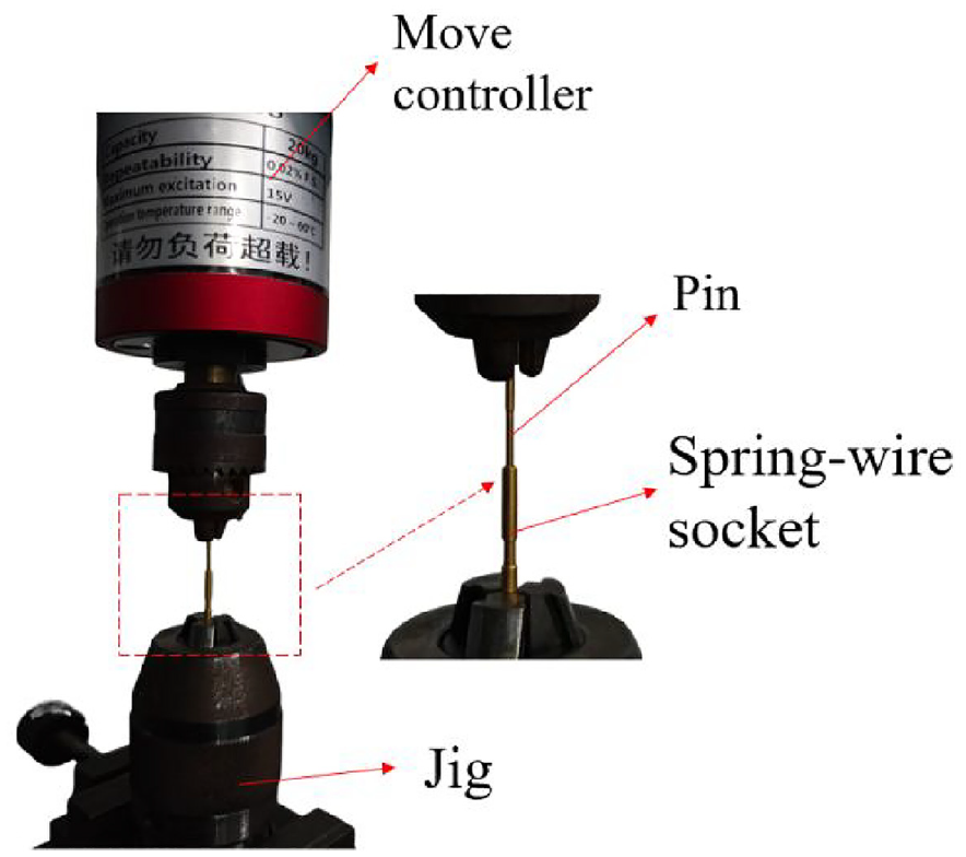
Insertions-extractions test instrument.
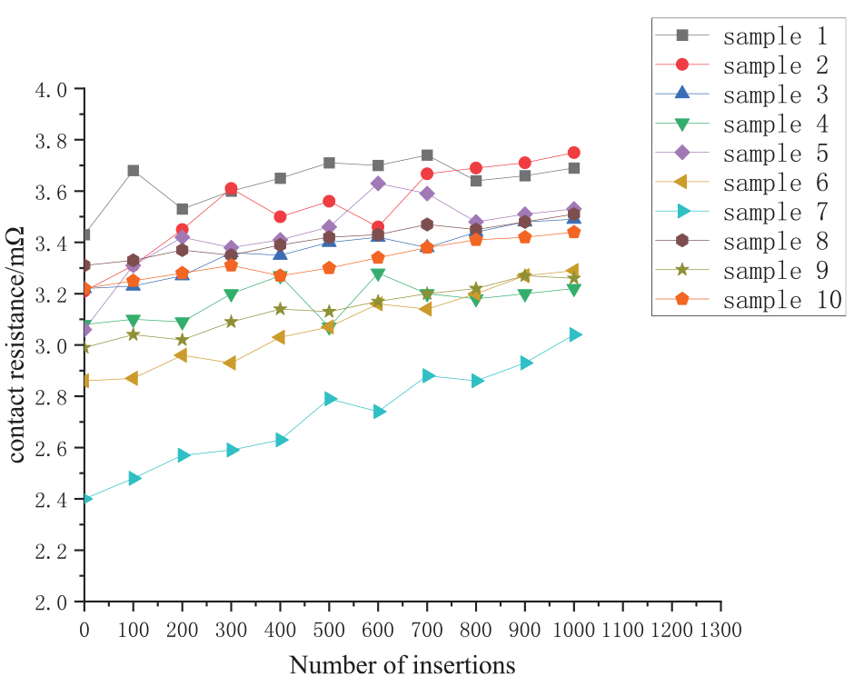
Test data diagram.
The maximum-likelihood-estimation method was used to process the collected test data, and
Maximum-likelihood-estimates

The value of
Parameter least-squares-fitting value.

Integrated contact design model
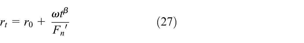
The number of contact pairs is g, and the resistance of the

Equation (28) can be transformed into:

Because

Let

Integrated optimization design of spring-wire socket electrical connector
Establishment of optimization objective function
It can be seen from equations (17) and (29) that the integrated reliability of the contact pair is related to the contact resistivity
To ensure the high reliability of the contact pair, the contact resistance needs to be minimized after multiple insertions-extractions. Therefore, the objective function is

Constraint conditions of optimization variables
(1) The contact is installed within the insulation and seal of the electric connector. If the difference between the optimized result and the initial value is too large, it will significantly affect the insulation, seal, and overall size of the electric connector. The contact pairs are standardized products. Therefore, considering the reliability requirements, the optimization criterion is the minimum size change, with the upper and lower limits of the optimization variables set at ±10% of the initial size.
(2) According to the requirements for the spring-wire socket electrical connector in the storage environment, it should withstand more than 1000 insertions and extractions, and its reliability for a storage life of 32 years at 20°C should be no less than 0.999, that is:

(3) When the pin is fully inserted into the socket, no gap between the inner sleeve and the spring-wire. The distance between them must meet the following requirements:

(4) To ensure the proper insertion of the pins and the spring-wire socket, the throat radius must not exceed the pin radius, that is:
(5) To ensure that the spring-wire returns to its original state when pulled out, it is necessary to prevent the spring-wire from undergoing plastic deformation during the insertions-extractions process. The spring wire must meet the following strength conditions:

(6) The contact pressure of a single spring-wire must meet the requirements:

(7) According to the structure of the spring-wire socket, the distance

(8) When the number of insertions-extractions exceeds 1000, the contact performance of the contact pair can still meet the requirements, that is, there is a set of solutions
Resolution
Compared with local optimization algorithms that can only find local optimal solutions, global optimization algorithms have been widely used because of their high accuracy rate, so GlobalSearch and MultiStart among global optimization algorithms are chosen in this paper, to compute the results faster, the initial value of iteration is chosen as
The optimization results were obtained using the GlobalSearch and MultiStart optimization algorithm, as shown in Table 4.
Optimization results.
Since the difference between the results of the two algorithms is not significant, the results of the GlobalSearch algorithm are used. By substituting the design results from Table 4 into equations (1)–(12), the contact pressure is calculated as 0.48 N. By substituting the optimized parameters into the integrated contact design model, it can be concluded that the contact resistance is 6.37 mΩ when the storage reliable life is
Conclusion
(1) This paper establishes a contact degradation model for electrical connectors that considers the effects of insertions and extractions. It also establishes an integrated design model that combines insertions-extractions performance and contact reliability.
(2) Based on the integrated design model, the optimization variables and objective function are determined. The optimal solution that satisfies the constraints is obtained using the optimization algorithm.
(3) The integrated design results provide the dimensional foundation for subsequent manufacturing processes. Provides a reference for the integrated design of other types of electrical connectors, such as slotted connectors.
Footnotes
Handling Editor: Sharmili Pandian
Declaration of conflicting interests
The author(s) declared no potential conflicts of interest with respect to the research, authorship, and/or publication of this article.
Funding
The author(s) disclosed receipt of the following financial support for the research, authorship, and/or publication of this article: This study was supported by Zhejiang Provincial Key Research and Development Program (2021C01133).