
Abstract
The master cylinder of most pump trucks is equipped with a waterproof valve, whose purpose is to prevent water from the tank from entering the master cylinder. Once waterproof valve fails to failure, the waterproof valve at the main cylinder can only be supported by a BS seal (this seal is very easy to fail), which results in oil emulsification and pollution of the hydraulic system. Therefore, a fault diagnosis method combining a multi-sensor high-dimensional time-domain feature expansion map (MHTFEM) with an attentional convolutional capsule network (ACCN) is proposed. In this method, the raw vibration signals acquired by all sensors are first preprocessed to generate a high-dimensional feature matrix. Then the different high-dimensional feature matrices are stitched, expanded and generated into grayscale images, followed by randomly dividing the training set and the testing set. Finally, the training set is brought into the ACCN for training and the testing set is brought into the network model for fault type identification. A test bench was built to confirm the effectiveness of the method for waterproof valve fault diagnosis. This provides a method to achieve intelligent fault diagnosis of construction machinery to ensure its reliability.
Keywords
Introduction
The waterproof valve is usually used at the main cylinder of the construction machinery pump truck. It mainly has two functions: during the pumping process, it prevents the cooling water in the water tank from entering the hydraulic system when the main cylinder moves back and forth, so as to ensure that the hydraulic system is not polluted; The pressure oil of the waterproof valve will increase the tension of the seal to achieve better sealing. The working environment of the pump truck is very harsh, it is difficult to control the source of hydraulic oil pollutants, and its working medium has been polluted to varying degrees. The waterproof valve working in the polluted medium is prone to failure. Once the waterproof valve fails, it is very easy to cause pollution of the whole system or emulsification of oil. Therefore, the research on effective fault diagnosis method of waterproof valve is of great theoretical and engineering significance.
At present, general fault diagnosis consists of signal processing and fault classification using different classifiers. For the purpose of fault diagnosis, researchers carry out a large number of studies.1–3 Vibration signals are time-varying signals, so extracting time-domain features among the signals can effectively characterize mechanical equipment faults. Jiang et al. 4 extracted time-domain and other features from the raw vibration signals to form high-dimensional features, and also obtained low-dimensional features among the high-dimensional features to effectively identify various faults of rolling bearings. Qiao et al. 5 implemented the problem of fault diagnosis of rolling bearings under different noise and load using features such as time-domain, which provides a reference for the problem of rolling bearing fault diagnosis. Jiang et al. 6 transformed the time-domain features of the collected signals into vector form and used SVM classifier for effective identification of faults in gears, rolling bearings and rotor cracks. The method of using time-domain features to achieve fault identification of mechanical equipment is feasible and effective, but due to the different methods of calculating time-domain features, the sensitivity to faults varies, making it difficult to identify faults in more complex or noisy background mechanical equipment.
By combining information from multiple sensors using a number of fusion methods, the accuracy of fault diagnosis results can be improved.7–9 For example, Xu et al. 10 fused the information from different sensors and input the fused data into a 2D-CNN (2D-Convolutional Neural Network) model to effectively identify different bearing faults in metro traction motors under different working conditions. Yan et al. 11 constructed a new multi-sensor data fusion fault identification algorithm using the coupling relationship between multi-sensor signals. The results of experiments conducted on rotating machinery demonstrate the effectiveness of the multi-sensor fusion algorithm. Yang et al. 12 took the gear fault in the gearbox as the research object, collected the sensor signals at different positions of the gearbox, then fused them, and combined the fused results with the machine learning method with fuzzy C-means. Finally, the diagnosis results were obtained. This method improved the reliability and diagnosis accuracy of the model. Inspired by the fault diagnosis method combining multi-sensor information fusion technology and machine learning algorithm, some research results in some specific fields (such as axial piston pump, 13 bearing, 14 gear, 15 etc.) have confirmed the effectiveness of this method.
As an extension and development of machine learning, deep learning16–18 has been widely used in fault diagnosis field. The most typical network model of deep learning is CNN and some variants based on CNN.19–21 Zhao et al. 22 proposed a normalized CNN, which shows strong performance in sample training and classification, and can be effectively applied to rolling bearing fault diagnosis. Wang et al. 23 studied the adaptive normalized CNN, which solved the great challenge of fault detection of planetary gear boxes caused by variable speed and variable load, and finally significantly improved the fault accuracy caused by the change of operating modes. Here, the network models of deep learning were mainly used for feature extraction. However, due to the diversity and complexity of fault features, some fault features can directly reflect the actual fault features, which can be used for fault diagnosis; while the fault information reflected by some fault features interferes with the accurate diagnosis results. In order to measure the influence of these fault features on the diagnosis results, the attention mechanism (AM) was proposed, which was mainly used to obtain the weight coefficients of different features to improve the accuracy of the model. For example, Yang et al. 24 combined CNN, gated recurrent units, and AM to diagnose bearings with different fault types, and the results showed that the introduction of AM enhanced the fault diagnosis of model. Li et al. 25 introduced AM to deep learning and achieved effective identification of rolling bearing faults. The attention mechanism help feature extraction of deep networks and brings higher accuracy to the experimental results.
This paper takes the waterproof valve on the concrete pump truck as the research object. Due to the bad working environment of concrete pump truck, including the dirty working environment of sand, stone, cement and dust in the construction site, as well as the long-term operation under high temperature or low temperature natural conditions, the working medium of the hydraulic system in the pump truck is prone to physical or chemical changes. In the polluted working medium, the waterproof valve is prone to wear or seizure of the internal working interface of the valve body and failure of the spring. Moreover, in the very large complex noise environment, these faults are difficult to be detected in the development process. Therefore, a fault diagnosis method combining multi-sensor high-dimensional time-domain feature expansion map and attention convolutional capsule network is proposed, which combines time-domain features, multi-sensor information fusion and deep learning to achieve effective identification of waterproof valve faults.
Highlights of this paper:
A raw data preprocessing method is proposed to generate a high-dimensional time-domain feature matrix from the raw vibration signal according to certain rules, which enriches the feature information.
The interconnection of multi-sensor high-dimensional time-domain feature matrices can well integrate the advantages of complementary data sources from homogeneous sensors.
An attentional convolutional capsule network for recognizing grayscale images is proposed, which introduces the convolutional attention mechanism into the convolutional capsule network to deeply explore the intrinsic features of grayscale images, which helps the learning and fault recognition of the network.
Working principle and fault description
The physical object of waterproof valve and its graphic symbols are shown in Figure 1. The working principle of the waterproof valve is a hydraulic principle: the continuous injection of oil in a limited confined space will produce an elevated pressure, and when the set pressure value is reached, overflow will occur. The oil inlet of the waterproof valve generally comes from the pressure oil source of the accumulator, and enters the oil passage between the two YX seals of the main oil cylinder through the valve. If there is water in the closed oil chamber, the pressure in the closed space will rise. Then the overflow valve of the waterproof valve will overflow the oil-water mixture, and finally be discharged into the cleaning tank through the T-port.

Description of Waterproof Valve: (a) physical photo and (b) simplified graphics symbol.
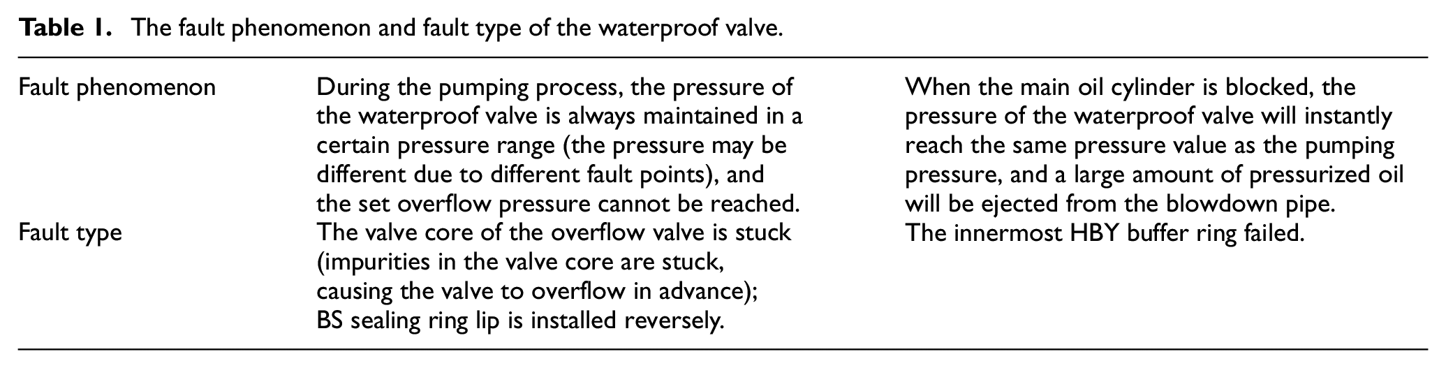
Based on the engineering experience, pressure gage, flowmeter and other traditional hydraulic detection methods, the fault phenomenon and fault type of the waterproof valve of the pump truck are obtained, as shown in Table 1. Although the traditional hydraulic detection modes can detect the fault of hydraulic components, it cannot explain the extent or position of the fault. Therefore, intelligent methods are required to replace the traditional hydraulic detection methods to check the development process of the waterproof valve fault.
The fault phenomenon and fault type of the waterproof valve.
Proposed method
In the process of fault identification, now most single sensor fault identification has not met the requirements for high accuracy, (1) the state information provided by a single sensor is limited; (2) when a single sensor is doing fault identification, there are differences in the different positions of the sensor arrangement for fault diagnosis results. Therefore, many scholars choose the multi-sensor method more often in the fault identification of mechanical equipment. This paper provides a new homogeneous sensor feature fusion algorithm, and combines deep learning for deep feature re-extraction, and then achieves accurate fault state identification.
Theoretical background
Convolutional neural network
The convolutional and pooling layers together build the CNN. The convolution operation is to extract different features of the input

Where
The pooling layers reduce the feature dimensionality of the convolutional layer output while preventing overfitting. Max pooling is a frequently used pooling operation, as follows:

Where
Capsule network
Capsule network is a new kind of neural network, each capsule network is composed of capsules. Neurons in the capsule layer exist as vectors, and the modal length of each vector indicates the probability of feature presence and is used as input and output. Key features within certain regions of the image can be captured to reduce feature information loss and improve the feature extraction capability of the model.
(1) Step 1 is similar to a traditional neural network, with the difference that the neurons in the capsule layer are in vector form rather than scalar form. The prediction vector

Where
(2) The output vector

(3) Step 3 is the nonlinear mapping of the output vector

Where
In the capsule network, after the above three steps, the dynamic routing algorithm can calculate the coupling coefficient


The process of dynamic routing is shown in Figure 2. First, the value of

The process of dynamic routing.
Convolutional block attention module (CBAM)
The proposed CBAM largely improves the feature extraction capability of the image and discards unnecessary region responses. Based on the analysis of the combination of channel dimension and space dimension, the CBAM26,27 is proposed. The input feature map


Structure of CBAM.
Multi-sensor high-dimensional time-domain feature expansion map
As shown in Figure 4, a new homogeneous sensor feature fusion algorithm, a multi-sensor high-dimensional time-domain feature expansion map (MHTFEM) data processing method, is proposed, which can transform the time-domain features extracted from the raw signal into a grayscale image, so that the whole grayscale image contains all the time-domain features of the signal. It is divided into: data pre-processing and data fusion, and steps are shown below:

Generate multi-sensor high-dimensional time-domain feature expansion map process.
Data pre-processing
(1) A signal shift window is set up, and a number of samples are obtained by sliding intercept samples with 6000 data points as one sample and 1000 data points as one step.
(2) A moving window of length 1000, 2000, 3000, 4000, 5000, 6000 is set in a sample with 500 sample points respectively.
(3) The 1000 moving window can intercept 11 sets of vibration data, and 13 time-domain features are extracted from each set of vibration data to obtain the feature vector
(4) The feature vectors obtained in step (3) are reconstructed into a high-dimensional time-domain feature matrix (HTFM)
Data fusion
(5) The HTFM obtained from the four acceleration signals are combined according to
(6) The MHTFM
(7) Repeat steps (2)–(6) to transform the next sample into a two-dimensional grayscale image.
In order to reduce the influence of the sensor arrangement position in step (5) on the final recognition results, a new set of sensors are arranged
Attentional convolutional capsule network framework
The convolutional capsule network is based on the original capsule network layer, and several convolutional pooling layers are prepended, and the convolutional pooling layer is used as a pre-feature extraction layer to perform shallow feature extraction on the input image. The features input to the capsule layer after shallow feature extraction are easier for the capsule layer to learn in order to achieve high accuracy feature recognition. Each neuron in the capsule layer exists in the form of a vector as a way to enrich feature information and improve the feature extraction capability of the model. The ACCN is to add CBAM before the capsule layer and after the second pooling layer to further capture the channel and spatial dependencies of the image features acquired by the convolutional pooling layer after the capsule layer to improve the robustness of grayscale image features, and improve the performance of the overall network model. Figure 5 shows the framework of ACCN.

The framework of the ACCN.
Detailed flowchart
Figure 6 shows the detailed flowchart of the waterproof valve fault diagnosis method. First, the establishment of waterproof valve fault signal acquisition test bench to collect the vibration signal of four positions. Then, through certain rules to extract the time-domain features of vibration signal, and composed of HTFM. Subsequently, the vibration signals collected from the four channels are generated HTFM, which is converted into grayscale images according to the stitching and expansion. Finally, the sample set is brought into the ACCN network model to achieve deep feature extraction and fault diagnosis to obtain diagnostic results.

Waterproof valve fault diagnosis method detailed flowchart.
Experimental validation
In this section, a test bench was built to verify the effectiveness of the proposed method by measuring the status information of the waterproof valve through four acceleration sensors.
Experimental platform
Figure 7 shows the mechanical device part and the data acquisition platform (The vibration signal acquisition equipment is manufactured by ECON, model AVANT MI-7016). As an important device on the main cylinder of the pump, the waterproof valve prevents water in the water tank from entering the main cylinder. Waterproof valve is a combination valve group (including overflow valve, check valve and pressure reducing valve), whose failure mainly occurs in the overflow valve. Under normal conditions, when the master cylinder seal chamber contains water and impurities, the pressure will increase and the mixed fluid (a mixture of water, impurities and hydraulic oil) will flow into the waterproof valve through the A port and flow out from the overflow port of the overflow valve when it exceeds the overflow pressure. In actual engineering practice, a lot of pollutant particles can affect the normal operation of the waterproof valve, resulting in different kinds of failures and changes in performance. The main fault is the wear of the interface between the valve core and the valve sleeve in the flow channel of the overflow valve, and even the locking of the valve core. The degree of contamination of the working medium is different, and the degree of failure is also different.

The experimental platform: (a) waterproof valve mounted on valve test bench and acceleration sensor location and (b) vibration signal acquisition device.
In this paper, different values of leakage and overflow are used to define different types of faults. A group of fault waterproof valves include health state and five different fault states, which are tested as tested objects. The fault types were shown in Table 2. The overflow pressure of the overflow valve is set to 100 bar, which means that when the oil pressure reaches 100 bar, the overflow valve opens and starts to overflow. Assuming that the pressure is added to 121 bar to port A, the flow rate of the overflow port is 9.7 l/min under normal healthy condition, and the flow rate of the overflow port is 8.5 l/min and 6.3 l/min under slight and severe locking condition respectively, and a group of experiments with a complete locking flow rate of 0 l/min are added. In addition to locking, spool wear occurs more frequently. Assuming a given pressure of 10 bar at port A, the leakage amount is 2.5 l/min for slight wear and 3.8 l/min for severe wear.
Waterproof valve fault description.
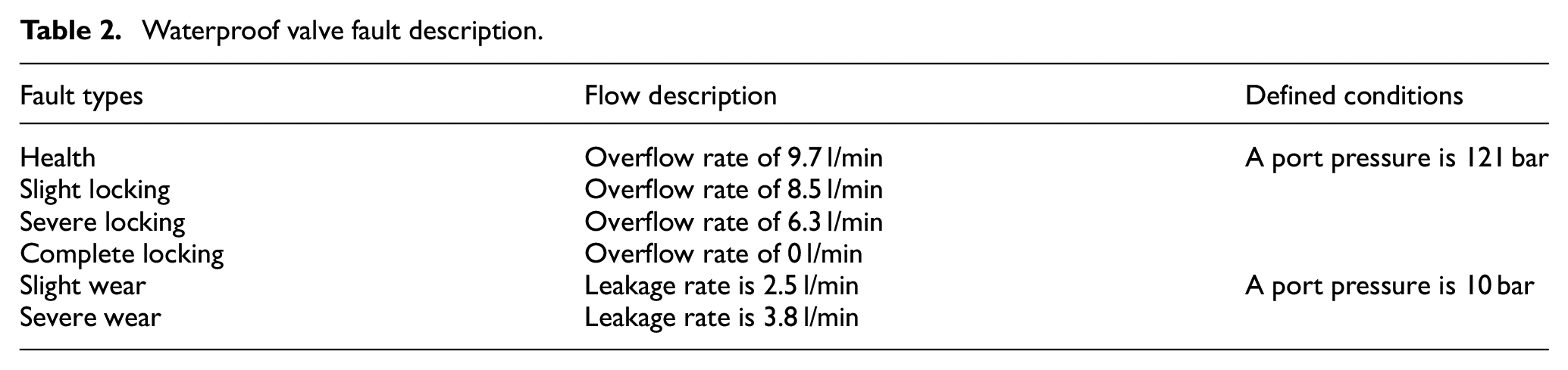
To bring the laboratory scenario closer to the actual operating conditions, a variable load pressure is delivered to port A, which is loaded in a 10-second cycle, showing a linear variation. Figure 8 shows the pressure-flow variation curves for the six states. The horizontal coordinate is the hydraulic pump setting pressure value, and the vertical coordinate indicates the flow rate value obtained from the overflow valve 2 port with a sampling frequency of 10 Hz. Comparing with the pressure-flow rate curve under normal condition, the overflow valve has a large value when the spool wear occurs. In the case of spool tightening of the overflow valve, the value of the overflow flow is small. Therefore, the method of defining different fault types by different values of leakage and overflow flow is feasible.

Pressure-flow curves for six states.
Data description
In this section, a valve failure test bench is used to collect one healthy state and five typical failures that can occur in waterproof valves, including slight locking, severe locking, complete locking, slight wear, and severe wear. The feasibility of the method in this chapter is verified by performing fault diagnosis for each state of the waterproof valve.
The vibration signals of the waterproof valve collected in various states are divided, with each segment length of 6000 samples as a sample. For each fault type 3000 samples are selected, and 2400 samples are randomly selected as the training set. Figure 9 shows the generated MHTFEM for the six states.

The generated MHTFEM for the six states: (a) healthy state, (b) slight locking, (c) severe locking, (d) complete locking, (e) slight wear, and (f) severe wear.
The samples were coded for six operating conditions: healthy, slight locking, severe locking, complete locking, slight wear, and severe wear: healthy (corresponding to label 1), slight locking (corresponding to label 2), severe locking (corresponding to label 3), complete locking (corresponding to label 4), slight wear (corresponding to label 5), and severe wear (corresponding to label 6). The testing set samples, training set samples, and the corresponding labels are shown in Table 3.
Number of training set, testing set samples and fault corresponding labels.

Parameter settings related to attentional convolutional capsule network
The attentional convolutional capsule network consists of several convolutional pooling layers, a CBAM and a capsule layer (parameters are shown in Table 4). The ACCN uses ReLU activation function in the convolutional layer to speed up the convergence of the model during training, to prevent overfitting. The features after convolution and pooling exist in scalar form, and then the CBAM features after re-extraction need to be reconstructed into vector form and passed to the capsule layer. The original input size is set to 224 × 224, and the output size is 56 × 56×16 features after two convolution and pooling over. After the second pooling layer, the pooled feature map is input to CBAM, and the size of the CBAM input and output before and after remains unchanged. after the CBAM output, the capsule unit is constructed, and the capsule layer output size is 6×(16), which represents six vectors of dimension 16.
Parameters of the attention convolutional capsule network.

Optimizer: Adam, learning rate: 0.001, epoch: 500, Batchsize: 128, and number of dynamic routing iterations: 3.
Fault diagnosis process
The process of the fault diagnosis method based on multi-sensor high-dimensional time-domain feature expansion map and attention convolutional capsule network is shown in Figure 10.
(1) Vibration signal acquisition: through the sensor waterproof valve in different states of the vibration signal, with a fixed sample length for overlap translation to divide multiple sample signals;
(2) Data pre-processing: extract the relevant time-domain features of the sample signals and generate a HTFM;
(3) Data fusion: The HTFM obtained from four sensors is combined to form a MHTFM, and expanded to generate grayscale images of equal size.
(4) Data set construction: the data sets in different states are randomly divided into training and testing sets;
(5) Network parameter setting and training: set network-related parameters, bring the training set into the network for training, and train the model by forward and backward propagation;
(6) Waterproof valve fault diagnosis: the testing set into the trained network for state identification, and the diagnosis results (model evaluation criteria: the average accuracy and model stability).
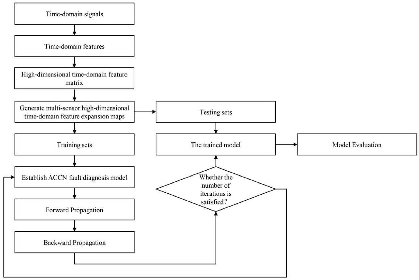
Waterproof valve fault diagnosis process.
Fault identification results
The training samples randomly selected according to Section 4.2 are delivered to the ACCN network model, and the testing set is used to verify the correct fault identification rate of the network model. The trends of training accuracy and validation accuracy are shown in Figure 11. After 300 iterations, the accuracy of the testing set stabilized, indicating that the ACCN network model reached the expected training effect and achieved excellent diagnostic performance.

Accuracy of ACCN network models obtained in the training and testing sets.
Comparison experiments
Comparison experiments of different fusion (or non-fusion) methods
In this paper, the HTFM generated from four sensor signals are stitched and expanded to generate grayscale maps, and the expected results are obtained in fault identification using ACCN network model. The superiority of the four-sensor HTFM fusion method provided in this paper is verified by combining different sensors in the following way.
A single-sensor HTFM of size 36 × 13 is generated by the same data preprocessing method as in this paper, expanding to a grayscale image of size 288 × 234 (denoted as No.1). Two single-sensor HTFMs are axially stitched with a size of 72 × 13 and expanded to a grayscale image of size 288 × 234 (denoted as No.2). A three-sensor HTFM is vertically stitched with a size of 36 × 39 and expanded to a grayscale image of size 288 × 234 (denoted as No. 3). The method in this paper provides a four-sensor HTFM (denoted as No.4).
A non-fusion method and three fusion methods are compared for diagnostic results, and the testing set samples are brought into the same network model to obtain the confusion matrix as shown in Figure 12. The horizontal coordinate of the confusion matrix indicates the predicted sample labels and the vertical coordinate indicates the true sample labels, and when the predicted sample labels are equal to the real sample labels indicate correct identification, the number of correct samples will be accumulated on the diagonal line. It is clear from the figure that the multi-sensor data fusion method outperforms the single-sensor method. The overall diagnostic accuracy of the four-sensor HTFM fusion method is higher than other multi-sensor fusion methods.
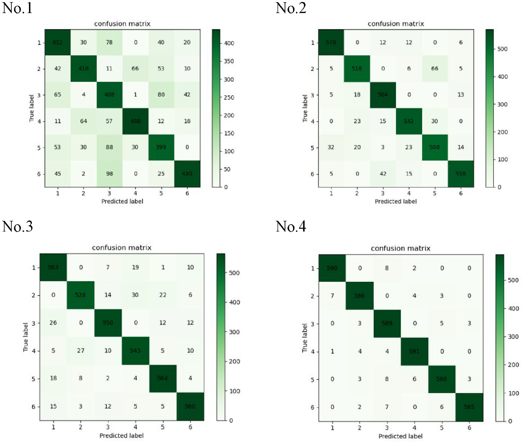
Confusion matrix obtained by different fusion (or non-fusion) methods.
Comparison experiments of different network models
To verify the superiority of the ACCNN network model in fault diagnosis, it is compared with three existing mainstream machine learning networks. Method 1-Method 4 represent the raw vibration signal using MTFEM method to generate two-dimensional grayscale images brought into VGG13, AlexNet, CNN and ACCN networks, respectively. VGG13, AlexNet and CNN are three mainstream deep learning networks, with which the comparison is representative. The fixed parameters of VGG13 and AlexNet are not elaborated in this paper, and the basic structure and setup parameters of CNN are shown in Table 5. The four methods were tested and the results were obtained as shown in Table 6.
Set parameters of the compared CNN.

Conv2D.16 means the 2D convolutional layer has 16 convolutional kernels, 3*1 means the size of convolutional kernel is 3*1, /1 means the parameter stride is 1, Maxpool2D means the 2D maximum pooling layer, and Dense128 means the fully connected layer has 128 parameters.
The corresponding experimental results of different methods.

Since network models have different sensitivities to different data sets, in order to reduce the influence of chance on the experimental results, three datasets A, B, C were randomly divided during the experiments. After each experiment, the data sets were re-divided, and the excellence of the model was evaluated by two indexes: average accuracy and standard deviation. In general, the higher the average accuracy and the smaller the standard deviation the better the model.


Where
In Table 6, by comparing method 1, method 2 and method 4, it can be seen that the three typical deep learning methods of VGG13, AlexNet and ACCN have higher recognition accuracy and better performance than the simple CNN network of method 3. This also shows that some methods of deep learning show powerful diagnostic capability in fault diagnosis. In the three sets of experiments in datasets A,B,C, the average accuracy of the diagnostic methods using ACCN model is 8.61% and 6.3% better than VGG13 and AlexNet, respectively. This indicates that the ACCN model has better diagnostic accuracy compared to other deep learning models in the face of larger data volumes.
Conclusions
Due to the working environment is very bad and the working state in the polluted medium is complex, it is difficult to identify or diagnose the fault of the waterproof valve. Therefore, a fault diagnosis method combining MHTFEM with ACCN is proposed. In this method, the raw data is generated into a HTFM by data pre-processing method, and then the HTFM of multiple sensors are fused and combined into a MHTFM by stitching, and finally the expansion process is performed before transforming into a two-dimensional grayscale image. In addition, the CBAM applied to the convolutional capsule network is used to focus on the important features of the image and suppress the unwanted regional responses to improve the diagnostic accuracy of the model. The experimental results validate the effectiveness of the proposed method, and the grayscale images generated by the combination of four sensors obtain the highest average accuracy and make the network the most stable model. Compared with other mainstream machine learning algorithms, ACCN can obtain an average accuracy of up to 96.77% and a standard deviation of 0.003 (indicating that the network is more stable). It provides a new method of intelligent fault diagnosis for hydraulic components.
Footnotes
Handling Editor: Chenhui Liang
Declaration of conflicting interests
The author(s) declared no potential conflicts of interest with respect to the research, authorship, and/or publication of this article.
Funding
The author(s) disclosed receipt of the following financial support for the research, authorship, and/or publication of this article: The authors are grateful to the support from the National Natural Science Foundation of China (No. 52175060), the Zhejiang Provincial Natural Science Foundation of China (No. LY20E050028).