
Abstract
The increase of the running speed of electric train has a certain influence on the dynamic performance of coupling of conductor rail and collector shoe. In this paper, the mechanical characteristics of coupling vibration between shoe and rail for high-speed trains are studied by using a numerical simulation method, and the effects of train speed on the vibration law of shoe-rail interaction system are analyzed. The results show that both the maximum displacement of the rail and the maximum contact force between the shoe and the rail increase with the increase of the train speed. The bending moment of the rail, the maximum displacement of the shoe, the elastic and viscous forces of the shoe all decrease first and then increase. In particular, when the train speed increases from 275 to 300 km/h, the displacement, bending moment, contact force, and other mechanical quantities increase significantly, which indicate that it will lead to a sharp increase in vibration degree when the train speed exceeds 275 km/h. Therefore, in the case of actual operating parameters in this paper, it is recommended that the train speed does not exceed 275 km/h.
Introduction
Conductor rail power supply mode has been widely used in the field of urban rail transit. However, the shoe-rail system is mainly used in medium- and low-speed rail vehicles. As the train running speed is higher and higher, the contact force between the shoe and the rail changes sharply, and the dynamic vibration amplitude is obviously larger, leading to some problems such as the separation of the collector shoe from the conductor rail, the instability of the current, the serious wear of the shoe, and so on. Therefore, it is necessary to study the interaction between the shoe and the rail.
The mechanical interaction of the shoe-rail system is mainly reflected in the dynamic behavior. There are two ways to study it, namely dynamic measurement of the shoe-rail system1,2 and dynamic simulation.3,4 The effects of train acceleration, temperature of conductor rail, construction accuracy of conductor rail anchor point, and conductor rail end elbow characteristics on the shoe-rail system were considered in the study of the shoe-rail dynamic behavior.5–8 In addition, Li et al. 9 and Xiang et al. 10 studied the effects of train speed, conductor rail parameters, and shoe-rail structural parameters on shoe-rail vibration characteristics. Li et al. 11 investigated the dynamic characteristics of the shoe-rail system, and analyzed the effects of the span of the conductor rail supports and train speed, such as the current collection quality and the variation range of dynamic contact force. Although the present researches have carried out a certain exploration on the coupling vibration of the shoe-rail system, the running speed is low.
With the development of urban transportation and people’s pursuit of travel efficiency, the demand for high-speed rail transit is gradually increasing and it is one of the directions for the development of urban rail transit in the future. Even though it is generally recognized that transport planning and management need to improve system performance during disturbances, as well as to reduce losses due to disruptions and disasters to the greatest extent possible, it is still challenging to address and identify appropriate implementation measures to reduce negative consequences. This is highly attributable to the lack of quantitative understanding of the evolution of system performance. 12 The train-induced vibrations affect system performance and also become a potential problem to historic buildings nearby. 13 Condition monitoring of rail transport systems has become a phenomenon of global interest. Condition monitoring of certain devices is applied in a particular system in order to detect changes or analyze trends in controlling particular parameters, and most of all to prevent potential failures of a system. 14
Studying the dynamic performance of shoe-rail interaction system at high speeds can provide guidance for practical engineering. However, the dynamic performance of shoe-rail interaction system is still absent under high speeds. The aim of this study is to numerically investigate the effects of train speed on the dynamic performance of shoe-rail interaction system, especially, the effects of high speeds on it.
Model and methods
Calculation model
The conductor rail can be simplified as a multi-span continuous Euler-Bernoulli beam. 15 The fixed position between the rail and railway foundation can be simplified as a fixed hinged support. The cross-section of the continuous beam remains unchanged. The distance between two hinged supports is equal.
The collector shoe is mainly composed of slipper, swing arm, spring, base, and other parts. It is actually a mechanism including inertia, mass, elastic stiffness, and damping. Zhang et al. 16 used the virtual displacement principle to derive the mass block equivalent model of the collector shoe, which is actually equivalent to a spring-damping oscillator with a single degree of freedom. Thus, the collector shoe can be simplified into a mass-spring-damping component.
The collector shoe is a moving part, and the conductor rail is a fixed part. Under a working condition, the shoe slides along the surface of the rail. We can simplify the shoe-rail interaction system, as shown in Figure 1.

The shoe-rail interaction model.
In this paper, we adopt the penalty function method to describe the coupling force between the shoe and the rail.
Numerical solution
The vibration equations of the shoe-rail interaction system can be obtained as a set of differential equations. Two micro-element segments,

Force analysis diagram of two micro-element segments.
In the coordinate system, point


They can be calculated as follows:


In the program calculation, we use the finite difference method for numerical integration, discretizing the differential equation into a difference equation, and then solving the numerical solution on the scattered point by writing a MATLAB program. For the selection of time step, we adopt an adaptive time step strategy. During the calculation process, the time step is automatically adjusted based on the changes in the solution to ensure the accuracy and stability of the calculation. Specifically, if the change in the solution is small, the time step is appropriately reduced to improve accuracy. If the solution changes significantly, the time step is appropriately increased to maintain the stability of the calculation. After many tests, the element length is set to be 5 mm and the calculation accuracy can be assured.
The parameters required for calculation
The conductor rail is steel-aluminum composite rail. The contact surface is steel strip and the bracket is aluminum alloy. Considering that the main material of the composite rail is aluminum alloy, the elastic modulus of the conductor rail is set as 70 GPa.
The actual cross section of the conductor rail is shown in Figure 3, which is rather complicated. We simplify it, as shown in Figure 4.

The actual cross section of the conductor rail.

The simplified cross section of the conductor rail.
According to the simplified cross section, the bending stiffness of the conductor rail can be obtained as 1.181×10⁵ Pa m4. The section modulus in bending is also calculated as 5.5317×10⁻⁵ m3.
Other parameters required in the calculation are shown in Tables 1 and 2.
Parameters of the conductor rail.

Parameters of the collector shoe.

The contact force between the shoe and the rail is calculated according to the contact stiffness and penetration displacement, and the contact stiffness of the shoe and the rail is 20,000 N/m. Wang and Luo 17 carried out relevant experimental studies, and calculated the contact pressure between the shoe and the rail through the vertical vibration acceleration of the shoe head and the strain of the rocker arm root, so as to study the distribution of contact pressure and the vibration of the shoe at different speeds. According to the experimental results, the initial contact force between the shoe and the rail in the calculation is set as 100 N.
Results
In order to study the effects of train speed on the dynamic performance of the shoe-rail interaction system, the numerical simulations are conducted when the train speeds are 200, 225, 250, 275, and 300 km/h under the condition that other parameters are the same.
Figure 5 shows the maximum vibration displacement of the conductor rail. It can be seen that it increases with the increase of train speed. The growth rate is relatively slow under the conditions of 200–275 km/h. However, when the speed increases from 275 to 300 km/h, the increase of the maximum vibration displacement is obvious sharply.

The maximum vibration displacement of conductor rail.
It can be seen from Figure 6 that the maximum bending moment of the conductor rail decreases when the speed increases from 200 to 225 km/h. The maximum bending moment increases first and then decreases when the train speed increases from 225 to 275 km/h. The variational trend of the maximum bending moment is relatively gentle whether increasing or decreasing. However, the maximum bending moment increases rapidly and significantly when the train speed increases from 275 to 300 km/h.

The maximum bending moment of conductor rail.
Figure 7 depicts that the maximum shear force of the conductor rail decreases when the train speed increases from 200 to 225 km/h. The maximum shear force slightly increases when the speed increases from 225 to 250 km/h. Under the train speeds from 250 to 300 km/h, the maximum shear force decreases.

The maximum shear force of conductor rail.
Figure 8 shows the time-dependent contact force of the collector shoe under different train speeds. It can be seen that the variational amplitude of the contact force is the lowest when the train speed is 200 km/h. The variational amplitude is the highest when the train speed is 300 km/h.
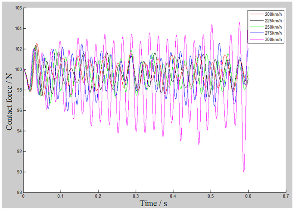
The contact force of collector shoe.
It can be seen from Figure 9 that the maximum variation of the contact force of the collector shoe increases with the increase of the train speed. Especially when the speed increases from 275 to 300 km/h, the maximum variation increases more obviously.
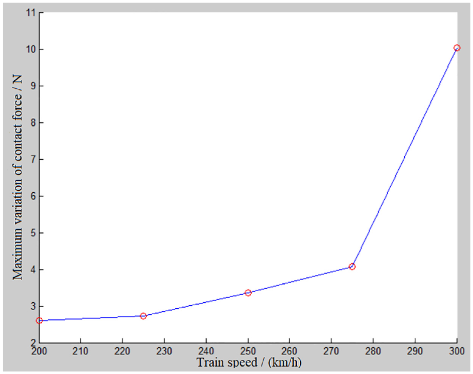
The maximum variation of contact force.
Figure 10 shows the variation of the viscous force of the collector shoe. It can be found that the amplitude of the change in the viscous force is the lowest when the train runs at 250 km/h, while it is highest when the train speed is 300 km/h.

The viscous force of collector shoe.
It can be seen from Figure 11 that the maximum absolute value of the viscous force of the collector shoe decreases when the speed rises from 200 to 250 km/h. However, the maximum absolute value increases when the train speed increases from 250 to 300 km/h. Especially, it has a sharp increase when the speed increases from 275 to 300 km/h.

The maximum absolute value of viscous force.
Figure 12 describes the change of elastic force of the collector shoe with time under different train speeds. It can be seen that the elastic force changes the most when the train speed is 300 km/h. It also gradually decreases with time.

The elastic force of collector shoe.
It can be seen from Figure 13 that when the speed rises from 200 to 250 km/h, the maximum variation of the elastic force of the collector shoe decreases. However, when the speed increases from 250 to 300 km/h, the maximum variation of the elastic force increases. Especially, it increases more obviously when the speed increases from 275 to 300 km/h.

The maximum variation of elastic force.
Figure 14 shows the change of displacement of the collector shoe with time under different train speeds. It can be seen that when the train runs at a speed of 300 km/h, the displacement of the collector shoe changes the most and it gradually increases with time.

The displacement of collector shoe.
It can be seen from Figure 15 that when the speed rises from 200 to 250 km/h, the maximum displacement of the collector shoe decreases. As the speed increases from 250 to 300 km/h, the maximum displacement increases. Especially, it rapidly increases when the speed increases from 275 to 300 km/h.

The maximum displacement of collector shoe.
Discussion
When the other parameters of the coupling vibration system of the collector shoe and the conductor rail are given and remain unchanged in practice, the maximum displacement of the conductor rail and the maximum contact force between the collector shoe and the conductor rail increase with the increase of the train speed in the range of 200–300 km/h. The maximum shear force of the conductor rail decreases first, then increases, but the increase is not obvious, and finally decreases with the increase of the train speed. On the whole, the variational trend of the maximum shear force of the conductor rail can be regarded as decreasing.
With the increase of the train speed, the maximum bending moment of the conductor rail decreases first, then increases, and then decreases again, but the decrease is not obvious, and finally increases significantly. Therefore, the variational trend of the maximum bending moment of the conductor rail can be regarded as decreasing first and then increasing. It can be seen that only when the train runs at a moderate speed, the vibration degree of the collector shoe and the conductor rail is relatively low. In particular, when the train speed increases from 275 to 300 km/h, the displacement, bending moment, contact force, and other mechanical quantities increase significantly, indicating that the higher the train speed, the more intense the coupling vibration.
Through the analysis of the contact force between the shoe and the rail, bending moment, displacement vibration, and other mechanical properties, it is found that when the speed exceeds 275 km/h, these mechanical properties increase sharply and significantly. It shows that when the speed exceeds 275 km/h, the fluctuation of contact pressure and the vibration of the collector shoe become more intense with the increase of the train speed.
At present, the speed of urban rail transit is mainly moderate, which ensures the low vibration of the shoe-rail interaction system. Thus, the train operation is safety and makes passengers comfortable. Our results have a good agreement with the fact. However, when the train speed increases to a certain extent, the shoe-rail interaction will induce a violent vibration. Furthermore, it may lead to the separation of the collector shoe from the conductor rail, the instability of the current, and the serious wear of the shoe. Therefore, there is the certain foresight for exploring the shoe-rail coupling vibration characteristics at high speeds from the perspective, and it can provide a theoretical support for the future development of urban rail transit. The novel contribution of this work is to investigate the dynamic performance of shoe-rail interaction system under high speeds and find that 275 km/h may be a limiting speed for the good shoe-rail interaction. Therefore, this work can provide the guidance for design and ensure the stability of trains during high-speed operation. Certainly, we only provide some preliminary suggestions based on the current numerical results. Due to the limitations of the numerical model, the results need to be validated through on-site measurements and data collection, which is a potential avenue for future research.
To reduce computational complexity, we adopt a planar model in this study, and only the vertical mechanical behaviors are considered and lateral vibration is ignored. In our future work, three-dimensional models with more influencing factors will be constructed to improve the computational accuracy.
Conclusion
In this paper, numerical simulation is used to study the effects of train speed on shoe-rail coupling vibration. The results show that when the velocity exceeds 275 km/h, the vibration intensity increases sharply, the contact condition deteriorates sharply, and the dynamic contact and current collection characteristics are poor. Therefore, the recommended speed for the collector shoe and conductor rail system is not more than 275 km/h for the above actual operating parameters.
Footnotes
Handling Editor: Chenhui Liang
Declaration of conflicting interests
The author(s) declared no potential conflicts of interest with respect to the research, authorship, and/or publication of this article.
Funding
The author(s) disclosed receipt of the following financial support for the research, authorship, and/or publication of this article: This work is supported by Research Project of China Academy of Railway Sciences Corporation Limited (2023YJ286).