
Abstract
In the tobacco processing stage leading to the production of cigarettes, there are strict technical requirements for the structure and proportion of different lengths of cut tobacco following the cutting process. Moreover, the lightweight design of the high-speed rotary-cutting blades is of significant importance during this stage. To better address issues related to the rational design of the blade structure in rotary-cutting cutters and the effective control of size proportion of cut tobacco, this paper establishes a CLSC blade design method featuring concave-convex edges and inter-edge grooves, and provides specific structural schemes. By introducing the structure of the cutting components of the cutter and the cutting process, and by analyzing the differences in layout features between RSEC and CLSC blade structures, as well as their relevance to tobacco cutting and shaping, this paper establishes the installation constraints and mechanical load model for cutter blades under rated conditions. Finite element methods were used to model and analyze both types of cutter blade structures, yielding static and modal analysis data. Furthermore, production verification was conducted on an SD EVO cutter, and data on the rate of different lengths of cut tobacco were obtained. The results show that the mass of the CLSC concave-convex edge cutter blade was reduced by 4.33%, and the static stiffness efficiency was increased by 2.37 times. Although the first-six natural frequencies of the CSLC blade showed degradation in modal analysis, it still met the equipment vibration usage condition. The production verification results indicated that the use of CLSC concave-convex edge cutter blades reduced the long cut rate by 2.48%, increased the medium cut rate by 2.29%, broken cut rate increased by 0.08%, and increased the short cut rate by 0.12%, with an overall reduction in the whole cut rate by 0.19%, achieving the objectives of reducing the long cut rate, controlling the whole cut rate, and not increasing the broken cut rate. The CLSC blades were able to operate continuously, stably, and safely on the rotary-cutting cutter machine. The research presented in this paper can provide a reference for the analysis and design of cutter blade structures in tobacco cutter machines.
Keywords
Introduction
In the tobacco processing industry, the cutting process in the tobacco making procedure is a key step that affects the quality of the tobacco product. The cutter in a tobacco cutting machine is the core processing equipment used for this step. Its primary function is to cut processed tobacco leaves into strands of plant tissue that meet the processing standards for width, with the width of the cut tobacco adjustable between 0.10 and 1.50 mm. Based on the cutting motion and the direction of blade rotation relative to the feed of the tobacco material, tobacco cutter machines can be classified into rotary-cutting and roll-cutting types. The rotary guillotine tobacco cutting machine, known for its high production efficiency and ample room for optimization, has long been a focus of research. 1
Research on controlled strand length cutting (CSLC) technology conducted on rotary-cutting tobacco cutter machines primarily aims to control tobacco strand length and optimize size proportion of cut tobacco, thereby effectively improving the quality stability of medium and slim cigarettes.2,3 Due to the different shapes and consumption patterns of various tobacco products, there is a heightened demand for control over the width of cut tobacco and the proportions of long and short strands. The main technical feature of CSLC technology, compared to regular straight edge cutting (RSEC) modes, CSLC is the use of blades with discontinuous edge intervals, designed to control the proportions of different lengths of tobacco strands in the cut product. This is particularly important for products like medium cigarettes, slim cigarettes, and heat-not-burn cigarettes, which require reduced long cut rate, controlled whole cut rates, and no increase in the broken cut rate to maintain quality stability. 4 Cutting blades in tobacco cutter machines continuously rotate at high speed on the cutting drum, cutting the compressed tobacco cake into strands meeting quality standards, and are the final executing parts in the cutting process. 5 Rotary-cutting tobacco cutter machines, as the main devices for applying CSLC technology, and the impact of this technology on product quality control are also key discussion points among industry experts.6,7 Qu et al. 8 compared different size parameters of CSLC blades with RSEC blades on the structure of finished tobacco, conversion rate of whole cut, and other indicators, further confirming the advantages of CSLC technology in controlling and improving the quality of slim cigarettes. However, their study only analyzed blades with semi-concave edge parameter for CSLC and did not provide a detailed analysis of the shape and design rationale of the CSLC blades. Wang et al. 9 studied the effect of cutting tobacco structure of CSLC on the release of NNK in cigarette smoke during successive puffs of slim cigarettes and proposed a model for the interaction between 40 mm blade length of CSLC process and the release of NNK in mainstream cigarette smoke. Zhu et al. 10 conducted comparative tests with slim cigarettes made from RSEC and 40 mm type of CSLC in cutting tobacco, finding that seven harmful components in mainstream cigarette smoke, size proportion of cut tobacco, and the distribution of tobacco density within the cigarette were all optimized to varying degrees. Thus, Zhu and Wang proposed that the use of CSLC technology can effectively control size proportion of cut tobacco and established a quantitative relationship between the size parameters of CSLC blades and the chemical components released in cigarette smoke after burning. However, these studies only reveal the qualitative relationship between choosing CSLC technology and controlling size proportion of cut tobacco from the perspective of tobacco product metrology, without delving into the structural analysis and design of CSLC blades from the perspective of advanced manufacturing cutting research. At the same time, the use of metrology and measurement methods to conduct research on the measurement and precision of size proportion of cut tobacco is indispensable. Tong et al. 11 designed an online machine vision measurement device that integrates technologies such as simulating manual grasping, visual image measurement, and automatic material feeding, when compared with traditional offline weighing and manual measurement methods, it showed significant advantages in automation and high precision. Liu et al. 12 established a tobacco strand width measurement method characterized by digital image processing technology, through the mean shift algorithm, the segmentation and extraction of tobacco strand width are realized, offering rapid response and high precision. However, the image-based measurement methods used by Tong and Liu involve converting image detection data into microscopic measurement dimensions of tobacco strands, and the current national detection standard YC/T 178—2003 13 explicitly points out that there is a significant difference between the calculation method that uses tobacco cut mass on different mesh sizes to measure size proportion of cut tobacco. Therefore, considering the large-scale use in the tobacco processing industry and the evaluation of processing quality measurements for advanced tobacco manufacturing equipment, these methods cannot yet be widely applied.
From the perspective of manufacturing and processing, insights can be gained from research results on cutting blades for woodworking and other plant fiber cutting. Yao et al. 14 conducted a study on cutting conditions and finite element modeling methods for wood materials, aimed at reducing vibrations in the handle of a vertical disc stump grinder, achieving significant optimization in the output weighted acceleration of the handle in the optimized vertical disc stump crusher. Li and Zhang 15 proposed a modeling method for the tensioning effect of woodworking circular saw blades after multi-point pressure tensioning, by systematically studying the loading force and speckle distribution conditions, they used finite element modeling to analyze the impact of multi-point pressure tensioning on the stress field and natural frequency of the circular saw blades, providing a design scheme for multi-point pressure tensioning of the saw blades. Therefore, it is essential to conduct structural analysis and optimization of key parts such as CSLC blades for tobacco cutter machines, and to analyze equipment reliability and product quality stability from the perspective of advanced manufacturing and processing.
After reviewing the literature, it is noted that there is almost no structural analysis or finite element modeling study on CSLC blades of rotary-cutting tobacco cutter machines. Therefore, improving tobacco cutter equipment with the integrated goal of enhancing size proportion of cut tobacco control and optimizing the mechanical properties of the blades is particularly important. This thesis provides a structural design method for CSLC with concave and convex blade cutting blades for rotary-cutting tobacco cutter machines. It analyzes the relationship between the structural characteristics of the CSLC blades and the tobacco cutting forming process, establishes a working load calculation model for the blades during the tobacco cutting process, and combines finite element modeling analysis data of two types of cutting blades before and after optimization. Finally, the optimized part structure and the effectiveness of size proportion of cut tobacco control are validated through machine application. The solution described below enables the CSLC blades to achieve an optimal structure with lightweight effects, while obtaining ideal size proportion of cut tobacco control results in practical production applications.
Cutting tool structure model
Functional structure composition of cutting drum
During the operation of tobacco cutter machine, tobacco materials enter the cutting chamber through the upper and lower feeding chains at a controlled speed and pressure. Multiple cutting blades distributed along the outer circumference of the cutting drum form a cylindrical cutting surface. With the linkage cooperation of material feeding control, cutting drum speed control, cutting chamber size control and other devices, the tobacco leaves are cut into leaf fibers with certain technological requirements. 16
As shown in Figure 1(a), the cutting blades of cutting drum on the rotary-cutting guillotine cutter machine is the group with the largest number of high-speed rotating components, and they are also one of the components that bear the largest working load and experience high periodic vibration frequency during the material cutting process. Each blade is driven by an independent stepper motor for feeding, and the feeding amount is minimized to extend its service life. At the same time, to maintain a high standard of cutting quality, the blades are continuously sharpened by grindstone wheels. The remaining blade quantity is calculated based on feedback control from each stepper motor, and the expected blade service life is displayed in real time on the device control panel. A total of 10 cutting blades are evenly positioned along the outer circumference of the cutting drum rotation circle, with the long side of the blades arranged parallel to the axis of the cutting drum, as shown in Figure 1(b). The blades are installed and positioned under the blade clip and mounting base, with the blade tip protruding by about 7 mm, as shown in Figure 1(c).

Schematic diagram of cutter drum device and cutting blade positioning. (a) SD EVO rotary guillotine cutter machine. (b) Cutting drum and blades assembly diagram: 1. Blade feed mechanism, 2. Stepper motor, 3. Blade clip, and 4. Blade. (c) Blade installation position diagram: 1. Blade clip, 2. Blade mounting base, and 3. Blade.
Structure and function of cutting blade
As shown in Figure 2, the cutting blade is rectangular thin plate-shaped structure, with a length, width, and thickness ratio of around 350:75:1. It can be divided into three areas according to spatial layout and functional distribution, namely the upper part is the blade tip area that performs cutting and allows the cut leaf fibers to flow through, including the cutting edge, front face, and rear face; the middle part is the blade body area that clamps the blade and supports it, which is most of the front and rear blade surfaces and also the material area and main load transmission area of the blade; the lower part is the blade bottom area that performs the linkage of the blade’s width-direction feeding with the stepper motor and controls the blade’s feeding, which is also the remaining blade area and main load bearing area.

The outline of cutting blade and division of functional structure.
Structure characteristics of improved controlled strand length cutting blade
As shown in Figure 3, the controlled strand length cutting is derived from the structure of conventional straight edge cutting blades. The overall size, functional area distribution, installed related assembly parts, and material property attributes are basically the same. The blade tip area of the controlled strand length cutting blade has a concave and convex rectangular intermittent cutting edge, and is mostly made of high-speed steel. There are six concave edges and seven convex edges. Among them, there are two types of convex edges, the standard length of the middle five and the longer length of the two on each side. The concave-convex blade intersection of controlled strand length cutting blade has a series of blade grooves with a width of 1.5 mm and a length of 75 mm, which are arranged at regular intervals. The function of the inter-blade grooves is to eliminate the cutting edge blind zone at the concave-convex blade intersection where continuous grinding is not possible, to maintain the continuous sharpness of the blade, and to further improve the quality effect of long filament cutting. Through the spatial layout of three types of cutting edges, namely the convex edge, concave edge, and inter-blade grooves, the cutting blade efficiently achieves controlled strand length cutting, structure regulation, and efficient use of the cutting blade.

The diagram of RSEC and CSLC blades.
Working load analysis of cutting blade
The analysis of the working load and constraints of cutting blades is the prerequisite for achieving correct structural analysis and finite element calculation. From a macro perspective of structural optimization, the yield strength, hardness, and stiffness of cutting blades are much greater than the material characteristics of tobacco. 17 The structural optimization of controlled strand length cutting blades is based on the overall structure of the conventional straight edge blade without changing the structure and function of the cutting drum and cutting chamber. 18 Therefore, the cutting blade is considered as a structural part of the cutting drum system, and it is necessary to study its structural characteristics under rated working load and high-frequency vibration conditions. From a micro perspective of the cutting process, in the research on the cutting process of rotary guillotine cutter 19 or related plant fiber cutting mechanism analysis, 20 there are computational methods for establishing working load sources and mechanical models based on engineering applications. 19 The cutting force and cutting resistance are a pair of forces and reactions. Taking the cutting resistance as the working load of the blade, it provides a basis for carrying out static and dynamic characteristic analysis of cutting blades.
As shown in Figure 4, during actual cutting, the blade contacts the tobacco material from the upper cutting chamber to the lower cutting chamber to end the cutting process, the cut tobacco material forms an arc surface with a chord length equal to the height of the cutting chamber. The working load calculation state is when the blade rotates to the horizontal position for right-angle cutting, which only has the main cutting resistance Ftz and normal cutting resistance Frz. The two together form the vector force of the cutting resistance vector. The main cutting resistance Ftz is the component force that is perpendicular to the cutting speed direction and has the largest value. This load is the reaction force generated by the thrown tobacco shred after cutting, which can be calculated based on the rated power of the cutting drum drive motor and related parameters of the cutting working condition. The normal cutting resistance Frz is perpendicular to the speed direction and passes through the center of the cutting drum’s rotational circle, pointing towards the blade. It can be considered that in tobacco materials, tobacco fibers are cut like wood materials with transverse cutting characteristics, 21 so tobacco materials “cake” can be regarded as having transverse cutting characteristics to meet the needs of controlling thickness and length of plant fibers more appropriately. In addition, in terms of end, longitudinal, and transverse cutting conditions, the normal cutting resistance Frz is much smaller than the main cutting resistance Ftz, 22 which can be calculated by multiplying the main cutting resistance by a working condition coefficient. In Figure 4, n is the rotational direction of the cutting drum, and v1 is the direction of slow and constant feeding of tobacco materials.


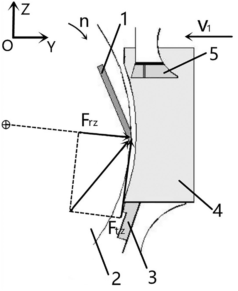
Working load and rectangular coordinate system of cutting blade under rated working conditions: 1. Blade, 2. Drum, 3. Lower cutting chamber, 4. Tobacco materials, and 5. Upper cutting chamber.
Based on the research on the cutting process of plant fiber materials and in conjunction with references An
22
and Liu,
23
the ratio of Frz normal cutting resistance to Ftz main cutting resistance is taken as:

The formula is as follows: Ftz is the main cutting resistance, N; Qdj is the rated power of the main motor driving the cutting drum, W; η is the transmission efficiency, taken as 0.95; Kx is the power correction factor, taken as 1.2; π is the ratio of a circle’s circumference to its diameter, taken as 3.14; D is the diameter of the cutting drum, mm; n is the rotational speed of the cutting drum, r min−1; τ is the unit cutting force, N mm−1; KK is the cutting condition coefficient, taken as 1.3 under cutting tobacco shred conditions; a is the rated height of the cutting chamber, mm; b is the width of the cutting chamber, mm; δ is the cutting angle, °; β is the angle of installation and adjustment of the cutting blade, °.
Finite element analysis model construction
Finite element analysis model preprocessing
Build three-dimensional models of the conventional straight edge cutting blade and the controlled strand length cutting blade. Import the solid model into ANSYS. Both cutting blades are made of high-speed steel W6Mo5Cr4V2 24 with a Poisson’s ratio of 0.3, elastic modulus of 2.18 × 10¹¹ Pa, density of 8.16 t m−3, yield strength of 1.25 × 10⁹ Pa, and tensile strength of 2.18 × 10⁹ Pa. Combining the literature on failure tests of thin plate-like parts, 25 where the ratio of wall thickness to mesh cell size is 1, and the simulation and cutting studies of high-speed steel blades, 26 where this ratio is 2, a balance between numerical simulation accuracy and computational time was sought. Taking into account the need for mesh sensitivity analysis, the ratio of blade thickness to mesh cell size was chosen to be 3.6. This means the model’s mesh is divided using automatic tetrahedral mesh cells, with a cell size of 1.5 mm.
Constraint and load addition
Set the bottom surface of the cutting blade and the front and rear surfaces of the blade body as fixed surfaces to serve as constraints. The cutting blade is in a stable and uniform motion state, and the cutting process at the moment when the blade edge rotates to the horizontal position is taken as a typical working load analysis state. Apply working load analysis forces to the blade tip area.
Static analysis
The cloud maps of the static analysis of the two cutting blade structures are shown in Figures 5 and 6, and the finite element simulation analysis results are shown in Table 1.
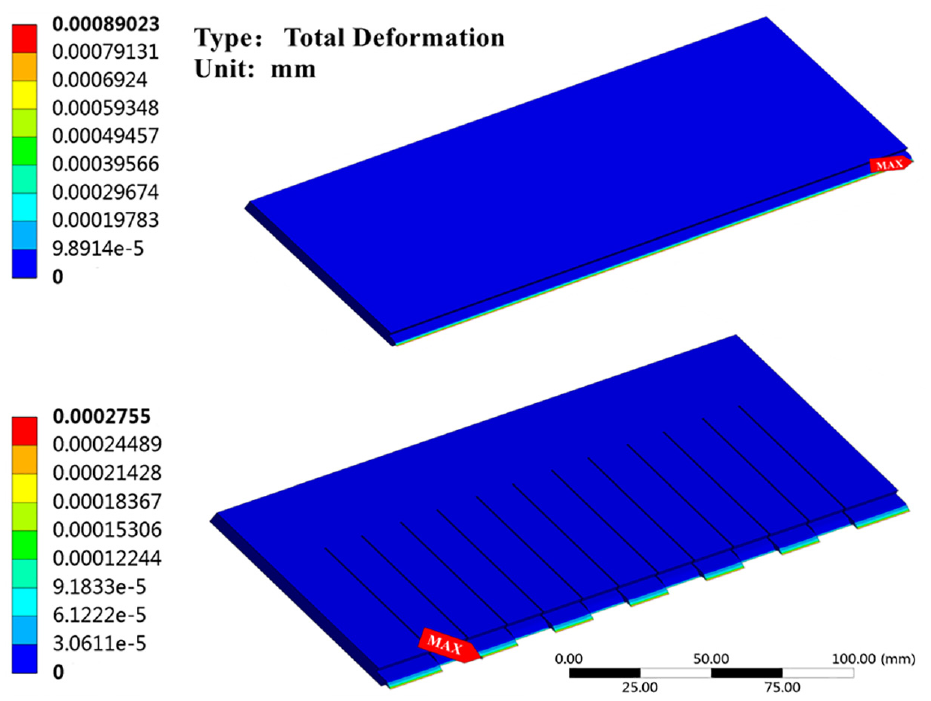
The results of statics analysis of total deformation cloud image of RSEC (up) and CSLC blades (down).

The results of statics analysis of Von-mises cloud image of RSEC (up) and CSLC blades (down).
The statics analysis simulation results of two kinds of cutting blade structure.

P.S:
Analysis results show that:(1) As shown in Figure 5, the maximum deformation position of the conventional straight edge cutting blade is at the outer tip of the blade tip area, with a maximum deformation δmax = 89.02 × 10⁻⁵ mm, and the maximum equivalent stress of the conventional straight edge cutting blade is at another outer tip of the blade tip area, with a maximum equivalent stress σmax = 41.27 MPa.
(2) As shown in Figure 6, the maximum deformation position of the controlled strand length cutting blade is at the left tip of the third convex edge, with a maximum deformation δmax = 27.55 × 10⁻⁵ mm. The maximum equivalent stress of the controlled strand length cutting blade is at the right tip of the sixth concave edge, with a maximum equivalent stress σmax = 10.05 MPa.
Compared with the conventional straight edge cutting blade, the mass of the controlled strand length cutting blade is reduced by 4.33%, and the maximum deformation in the blade tip area is significantly reduced by 69.03%. The maximum deformation position is mainly distributed at the tip points of the blade tip area. The maximum stress value is reduced by 75.61%, and the static specific stiffness efficiency of the structure is increased by 2.37 times. The maximum deformation of both structures is within a reasonable range, and much smaller than the allowable control motion error of 0.001 mm of the cutting drum. The maximum equivalent stress of both structures is much smaller than the failure criterion load stress, so there will be no fatigue fracture. Through optimizing the spatial layout design of the blade tips, the static specific stiffness efficiency level of the controlled strand length cutting blade is significantly better than that of the conventional straight edge cutting blade structure.
Modal analysis
Vibration and noise will be generated in the high-speed cutting process of the cutting machine, so it is necessary to perform modal analysis on the high-speed moving parts structure. 19 The higher frequency excitation source of the blades group on the cutting machine cutter drum mainly comes from the vibration of the main motor, and the lower frequency excitation source comes from the plant fiber fracture and collision of sand and hard particles when the cutting blade cuts the material. Both excitation frequency ranges are greatly different from the nature frequency range required by the cutting machine design. Taking the first six-natural frequencies of the structure as the analytical range, the fixed constraints are the front and back surfaces of the blade body and the bottom surface of the blade.
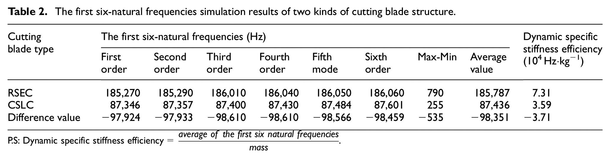
The first-order modal simulation cloud image results of the two blade structures are shown in Figure 7, and the comparison results of the six natural frequencies are shown in Table 2. The first six-natural frequency change line chart is shown in Figure 8. The main drive motor of the cutting drum operates at a speed of 1500 RPM, while the actual maximum speed of the cutting drum is 500 RPM, with 10 blades mounted on it. During a single rotation of the cutting drum, each blade experiences two significant amplitude vibrations when engaging and disengaging the tobacco due to the transition of cutting states. Therefore, theoretically, the excitation frequency generated by the drive transmission of the cutting drum and its cutting action should be at least around 167 Hz. The first-six natural frequencies of the RSEC and CSLC blades in modal analysis show similar macroscopic deformation patterns, with the maximum deformation occurring at the unknown tip of the blade. The results of the static analysis previously mentioned also indicate the maximum deformation at the same location, suggesting that the maximum deformation at the blade tip is influenced by both static and dynamic properties. The first six-natural frequencies of each structure are gradually increasing steadily and no large span frequency step phenomenon occurs. Although the first six-natural frequencies of the controlled strand length cutting blade are lower than those of the conventional straight edge cutting blade, they are all above 87,000 Hz, which is far greater than the main motor vibration and maximum speed cutting frequency of the cutting machine. Among them, the frequency range of the controlled strand length cutting blade is further narrowed, and the smaller structural natural frequency bandwidth is more conducive to controlling equipment resonance. Through comprehensive comparison of dynamic specific stiffness efficiency, 18 although the dynamic specific stiffness efficiency of the controlled strand length cutting blade is weaker than that of the conventional straight edge blade structure, The width dimension of the bottom part of the optimized CSLC blade is still maintained at no less than 35 mm. This part is connected to the stepper motor that controls the blade feed motion, which is used to control the amount of grinding feed to maintain the sharpness of the blade edge during its service cycle. Moreover, the protrusion of the concave and convex edges of the CSLC blade during cutting operations is still able to be maintained at no less than 7 mm as shown in Figure 1(c), and the natural frequency of the CSLC structure fully meets the normal operating conditions of the cutting drum and its equipment.

Modal analysis results with the first natural frequency max deformation of RSEC (up) and CSLC blades (down).
The first six-natural frequencies simulation results of two kinds of cutting blade structure.
P.S:

The first six natural frequency line diagrams of the two cutting blade structures.
Application and effects
Materials and methods
Materials: “Lanzhou” brand H-sized cigarette tobacco in process (provided by Lanzhou Cigarette Factory of Gansu Tobacco Industrial Co., Ltd.).
Equipment: SD EVO rotary guillotine cutter machine (Italy Garbuio Dickinson Group), YQ-2 tobacco vibration sorting sieve (China Zhengzhou Jade Technology Co., Ltd.), ME5002TE electronic balance (Metler-Toledo Instrument Co., Ltd.), YGD560 filling value tester (China Zhengzhou Jade Technology Co., Ltd.).
Method: The SD EVO rotary guillotine cutter machine used on the production line of Lanzhou Cigarette Factory was tested using two types of cutting blade structures for comparison. According to the manufacturing standard (10,000 kg/batch) of “Lanzhou” H-sized cigarette processing manufacturing enterprises, the conventional straight edge blades and controlled strand length cutting blades (10 pieces/group) were used on the same cutter machine with basically the same main equipment power and speed settings for production. Each cutting type selected five consecutive production batches, and 1000 ± 100 g/time·batch of samples were taken at the outlet of the flavoring machine. According to the Chinese standard of YC/T 178-2003 method, 20 the collected “Lanzhou” H-sized cigarette’s tobacco shred was separated and collected from the sieve outlet box, and each 3.35 mm, 2.50 mm, 1.00 mm sieve and the receiver plate were recorded as long cut rate, medium cut rate, short cut rate and broken cut rate by weighing and calculating their respective ratios to the total mass, as shown in Table 3. As shown in Figure 9, after using controlled strand length cutting blades, the internal and external structures of the cutting machine cutter drum were collected. The data were presented graphically as shown in Figure 10.
Comparison of size proportion of cut tobacco data between two cutting edge production modes before and after optimization.

P.S:

The production field image of cutter drum with CSLC blade, inside (left) outside (right).

Comparison and change of size proportion of cut tobacco between two cutting types.
According to the analysis of the size proportion of cut tobacco data using the controlled strand length cutting blade compared to the conventional straight edge cutting blade, the overall whole cut rate decreased by 0.19%, the long cut rate decreased by 2.49%, the medium cut rate increased by 2.29%, the short cut rate increased by 0.12%, and the size proportion of cut tobacco regulation changed significantly. The broken rate increased by 0.08%, and the filling value increased by 0.02%, with the change values all within an acceptable range. Based on the above data, it can be found that using controlled strand length cutting blades can achieve the transfer of long cut rates to medium and short cut rates, and a reasonable blade shape design can ensure that the shred rate changes are controllable and have no significant impact on the tobacco filling value. The trend changes in the experimental data not only support the trend judgment of the size proportion of cut tobacco regulation method using the controlled strand length cutting type,2,4 but also show that using with a concave-convex blade and inter-blade grooves structure blades as a realization scheme cutting type is more in line with the purpose of controlled strand length cutting technology in terms of design rationality, application effectiveness. The long cut rate (≥3.35 mm) and increasing the proportion of short-medium cut rate (1.0–.35 mm), the mass, draw resistance, hardness, and density stability of cigarettes can be improved. 27 By controlling the rate of size proportion of cut tobacco during the tobacco cutting process, it is possible to reduce the fragmentation during the subsequent cigarette rolling process. Through the optimization of size proportion of cut tobacco in the preliminary tobacco processing stage, the goal of effectively enhancing the size distribution and uniformity of tobacco filling within the cylindrical cavity of the cigarette after rolling is achieved, 8 leading to an increase in the stability of the granular system and ultimately enhancing the physical properties of the rolled cigarettes to align more closely with the design, manufacturing standards, and quality stability.
Conclusion
This paper aims to address issues related to the blade shape structure design, light weighting, and the effectiveness of size proportion of cut tobacco control in rotaty-cutting tobacco cutter machines. It establishes a design method for CLSC blades featuring concave-convex edges and slots between blades, providing specific structural solutions. Through theoretical analysis, finite element method simulations, and on-site verification in production, the innovative optimization design and application of cutting blades were completed. The main conclusions are as follow:
(1) The optimized CLSC blades have a 4.33% reduction in weight, further achieving the goal of lightweighting for high-speed moving parts.
(2) The maximum equivalent stress value of the optimized CLSC blades decreased by 75.61%, enhancing the blades’ resistance to fatigue failure. The static specific stiffness performance significantly improved by 2.37 times. Although the first six-natural frequencies in the modal analysis of the CLSC blades decreased, they still meet the equipment usage requirements.
(3) On-machine testing of the optimized CLSC blades on the SD EVO cutter machine showed that using CLSC blades could reduce the long cut rate by 2.48%, increase the medium cut rate by 2.29%, increase the short cut rate by 0.12%, increase the broken cut rate by 0.08%, and decrease the whole cut rate by 0.19% overall, the filling value of tobacco is basically stable and unchanged, achieving the objectives of reducing the long cut rate, controlling the whole cut rate, and not increasing the broken cut rate. Moreover, the blades could be used continuously, stably, and safely on the cutting machine.
(4) Systematic research and analysis of CSLC blades and its’ technology are of significant practical application importance for enhancing specialized and demand-driven equipment in tobacco processing technology, primarily using advanced manufacturing techniques. However, the methods and technologies discussed in this paper focus only on one of the two mainstream types of tobacco cutting equipment, namely the rotary-cutting machine, and do not consider the principles of related fixed-length cutting technology in roll-cutting machines. Therefore, from the perspective of systematizing and completing the fixed-length tobacco cutting methods and research system, further in-depth work is needed.
Footnotes
Handling Editor: Chenhui Liang
Declaration of conflicting interests
The author(s) declared no potential conflicts of interest with respect to the research, authorship, and/or publication of this article.
Funding
The author(s) disclosed receipt of the following financial support for the research, authorship, and/or publication of this article: Gansu Tobacco Industry Co., Ltd. Technology Project (No.KJXM-2022-07).