
Abstract
Developing optomechanical systems with large-aperture output beams is increasingly important for deep space exploration, homeland defense, and modern warfare. However, the assembly process for such systems is becoming more challenging due to their complexity and size. Considering that traditional computer-aided assembly methods for optomechanical systems primarily prioritize debugging and testing, often overlooking the importance of feasibility analysis and verification in the assembly process, this paper presents a digital assembly method for large aperture optomechanical systems that integrates virtual assembly technology with misalignment error detection technology. By combining these two technologies, the proposed method aims to enhance the assembly process by providing a more comprehensive approach that includes feasibility analysis and verification, in addition to debugging and testing. Firstly, virtual assembly technology is utilized to simulate and validate the assembly process design of optomechanical systems. Secondly, a second-order sensitivity matrix method is proposed to achieve higher accuracy in solving misalignment compared to traditional methods. The new method is validated through simulation experiments on an off-axis beam expander system, showing superior solving accuracy compared to traditional approaches. Lastly, an actual assembly and adjustment platform is constructed, and the obtained assembly result exhibits a wavefront aberration RMS value better than 0.016λ (λ=632.8nm).
Keywords
Introduction
Reflected optical systems offer several design advantages compared to transmissive optical systems. These advantages encompass high reflectivity with minimal energy loss, absence of chromatic aberration, a straightforward and compact structural configuration, as well as the capability to design large apertures.1–3 The aforementioned attributes make reflected optical systems extensively employed in advanced optical systems for military and aerospace applications. Nevertheless, enlarging the aperture size of optical components presents challenges in terms of assembly precision and the design of the assembly process, as it leads to an overall increase in the size and mass of the optical system. Therefore, the assembly technology for large-aperture optical systems faces significant challenges. The technology utilized for assembling optical systems, commonly referred to as computer-aided assembly technology,
4
concentrates on identifying misalignment errors and resolving assembly issues specific to reflective optical systems. Currently, there are several mainstream methods used to solve misalignment errors, including the sensitivity matrix method,
5
evaluation function regression method,
6
artificial neural network method,7–9 and vector aberration modeling method.10–15 An analysis was conducted by Hvisc and Burge
16
to determine the sensitivity of the spherical aberration corrector of a four-mirror configuration of the Southern African Large Telescope (SALT) using a sensitivity matrix. Gong et al.
17
used the sensitivity matrix method to assemble an off-axis three-reflection system, achieving a superior assembly result of
Jayaram and Wang from Washington State University and the National Institute of Standards and Technology (NIST), along with their colleagues, have collaboratively developed the world’s first Virtual Assembly Design Environment (VADE). The VADE system integrates an immersive virtual environment with commercial Computer-Aided Design (CAD) systems to assist engineers in the evaluation, analysis, and planning the assembly processes of mechanical systems. 20 Liverani and Amati have developed a wearable virtual assembly system, known as Personal Active Assistant (PAA), based on CAD assembly software and augmented reality technology. The PAA system enables the monitoring of complex datasets. Its internal virtual reality-based assembly evaluation tools support direct interaction between users and assembly operators, allowing for the manipulation of both real and virtual prototype parts. 21 Enrique and Hugo have developed a virtual assembly system that incorporates haptic feedback. The system not only simulates and automatically generates assembly plans but also evaluates them effectively based on the execution of virtual assembly tasks. Objective assessment of assembly strategies in virtual assembly is achieved by introducing and utilizing multiple performance indicators. 22 Eswaran and Hymavathi have developed an automated assembly method that utilizes augmented reality (AR) visualization technology. This method confirms the feasibility of assembly sequences in a virtual reality environment while facilitating the generation of virtual content for AR visualization. Moreover, the team investigates AR custom calibration techniques to achieve AR content visualization from the user’s perspective within the physical environment, thereby enabling real-time execution of assembly operation demonstrations. 23 However, the current research focus on virtual assembly technology primarily revolves around enhancing the effectiveness of human-computer interaction. This achievement is realized by utilizing augmented reality technology to offer more realistic demonstrations of the assembly sequence during the training process. However, there is relatively limited research on the theoretical study and technological application of assembly process simulation for large-scale and structurally complex mechanical systems.
In this paper, a digital assembly technology for large-aperture optomechanical systems is proposed to address the challenges of complex assembly processes and difficulties in ensuring assembly accuracy. This technology enables the simulation and verification of assembly process schemes for optomechanical systems, as well as the precise calculation of optical component misalignment. It provides key technical support for the assembly process of large-aperture optomechanical systems and fills the gap in the integration of assembly process simulation verification and misalignment error detection for such systems. Section “Method” introduces the technical architecture of the digital assembly method, which specifies the specific content of digital assembly process planning and provides the technical roadmap and theoretical derivation process for key technologies. In Section “Experiment,” the feasibility of the proposed method is verified through the construction of an optomechanical virtual assembly system, simulation experiments on an off-axis beam expanding optomechanical system, and actual assembly and adjustment experiments. Section “Conclusions and future work” presents the conclusions and discusses future research directions.
Method
Digital assembly method technology architecture
The research and development process of an optomechanical system comprises four main components: requirement analysis, systems design, assembly process, and final debugging, as illustrated in Figure 1. Requirement analysis primarily entails analyzing the functional requirements and performance specifications of the optomechanical systems, ultimately providing technical specifications for the design team. The systems design process follows a bottom-up design approach, beginning with part design, followed by component design, and culminating in product design. The assembly process of optomechanical systems is primarily divided into two stages: virtual assembly and actual assembly. Through virtual assembly technology, the assembly process is replicated virtually, validating the feasibility of the proposed solution and providing guidance for physical assembly, ultimately completing the assembly of real optomechanical systems. The final debugging refers to the process of using misalignment detection technology to fine-tune the systems after the complete assembly of optomechanical systems. Thus, the integration of virtual assembly and misalignment detection technologies is vital for the digital assembly of large-caliber optomechanical systems.

Technical architecture of digital assembly method.
The core content of digital assembly technology
Design of digital assembly process planning
In the assembly process of an optomechanical system, it is essential to develop specific assembly processes for each individual component. Figure 2 depicts the evolutionary model diagram of the digital assembly process design. The conventional assembly process design comprises four stages: workshop layout, personnel scheduling, on-site assembly, and problem feedback. The design is presented through assembly process cards that rely on written text. Thus, during the feasibility verification analysis of assembly processes, the assessment is solely reliant on textual descriptions and images within the assembly process cards, which excludes the simulation and demonstration of the assembly process. Problem feedback serves solely to modify the initial assembly process according to the on-site assembly results. This approach requires significant human resources and delays the overall progress of the assembly plan for optomechanical systems.

Evolutionary model of digital assembly process design.
The utilization of virtual reality technology allows for the recreation of the site layout and personnel scheduling based on the assembly process design in a virtual environment. Through simulating the assembly process of optomechanical systems in this virtual setting, any potential issues in the assembly process design can be identified and promptly addressed. This advancement transforms the assembly process design, traditionally presented in written form, into a three-dimensional visualized virtual assembly technology. The application of this technology plays a crucial role in ensuring the successful assembly of large-caliber optomechanical systems.
Hierarchical structure of digital assembly sequence
The hierarchical structure of the optomechanical systems in the assembly sequence is illustrated in Figure 3. The assembly process of a complex optomechanical system comprises three levels: final assembly, subassembly, and part assembly. Part assembly activities form subassembly activities, and subassembly activities form the final assembly activity. Consequently, the assembly process of optomechanical systems consists of multiple subassembly processes, and the implementation of the final or subassembly process involves seven stages, as depicted on the horizontal axis of Figure 3. During the virtual assembly stage, the complex assembly process is broken down into more detailed subassembly processes at a lower level, enabling a systematic analysis of the feasibility of systems assembly process planning. The decomposition of a complex virtual assembly process into multiple simpler processes enhances the efficiency and accuracy of the virtual assembly verification process. 24

Hierarchical diagram of the optomechanical systems assembly sequence.
The specific contents of the digital assembly phase
The digital assembly process of large-caliber optomechanical systems is divided into seven stages, spanning from product design to on-site debugging. These stages include systems design, assembly process design, virtual site layout, virtual personnel scheduling, virtual assembly, problem feedback, on-site assembly, and debugging, as illustrated in Figure 4.

Schematic diagram of the specific contents of each assembly stage.
In the systems design stage, designers develop the 3D model, 2D drawings, and relevant technical specifications of the optomechanical systems in accordance with the specified technical and functional requirements. These designs are subsequently allocated to assembly technicians. During the assembly process design stage, assembly technicians generate the relevant assembly process content in line with the requirements specified in the design of the system. This encompasses the comprehensive planning and arrangement of the site, equipment, personnel, and material preparation. In the virtual site layout stage, the site, equipment, and materials specified in the process planning are faithfully replicated in a one-to-one fashion within a virtual space. Appropriate site divisions are established for distinct operational processes. Virtual personnel scheduling entails the logical allocation of virtual entities according to the assembly process content. This encompasses the determination of personnel numbers, their allocation, and their corresponding task responsibilities. Virtual assembly commences once the virtual environment setup is finalized, encompassing the simulation and rehearsal of the assembly process for the optomechanical systems. Appropriate configurations are determined for the spatial positions and orientations of different components during the assembly process. A feasibility analysis is performed on the initial assembly process plan, emphasizing the identification of potential spatial interference concerns involving parts, equipment, personnel, and collaborative assembly operations. Problem feedback entails the analysis and evaluation of the logicality of site layout, personnel scheduling, and assembly processes during virtual assembly. Subsequently, any issues detected during the virtual assembly stage are provided as feedback to refine the original assembly process design. On-site assembly and debugging encompass the actual assembly of the optomechanical systems following a virtual feasibility analysis of the assembly process. Once the assembly is finalized, calibration and fine-tuning of the optomechanical systems occur through the debugging process.
Key technologies
Digital assembly technology, as depicted in Figure 5, is utilized in large-aperture optomechanical systems, incorporating virtual assembly technology and misalignment error detection technology. Virtual assembly technology encompasses virtual roaming technology, assembly process simulation technology, and human-computer interaction technology. Virtual roaming technology is employed to establish a virtual assembly environment and regulate virtual personnel’s movement within the environment while allowing them to observe the assembly process. Assembly process simulation technology facilitates real-time simulation of the assembly process and identifies potential interference between the model and the surrounding environment during virtual assembly. By integrating virtual roaming technology and assembly process simulation technology, human-computer interaction technology enables the development of an assembly system that can be operated by personnel. The misalignment error detection technology utilizes an enhanced second-order sensitivity matrix solution algorithm to precisely address component misalignment within the optomechanical system, facilitating efficient system debugging.

Decomposition and functional implementation of digital assembly technology for large-caliber optomechanical systems.
Virtual roaming technology
The technology roadmap for the virtual roaming technology is illustrated in Figure 6. The virtual roaming technology is an application that utilizes virtual reality technology. It employs modeling software like Unity3D, 3ds Max, and CAD to construct a virtual assembly environment, accurately simulating the real assembly environment, encompassing the site, equipment, lighting, personnel, and more. This allows users to actively participate in immersive roaming and interact within the virtual environment. Virtual roaming technologies can replicate the unrestricted movement of individuals in real-world roaming within the virtual environment, utilizing devices like a mouse, keyboard, and display. Unity3D software allows the creation of control scripts to govern the movement of character models in the virtual world. For instance, character models can be controlled to simulate the movement of individuals in real-world roaming by performing actions like moving forward, backward, left, right, and rotating. Perspective roaming entails establishing a virtual camera within the virtual world and implementing control scripts to alter the camera’s observation direction and scope, accurately simulating the changes in the visual field experienced by the human eye during real-world observation.

Roadmap of virtual roaming technology.
Assembly process simulation technology
Assembly process simulation technology primarily performs feasibility analysis of assembly process content, focusing on the presence of interference phenomena between models, models and the environment, and models and equipment during the assembly process. The schematic diagram in Figure 7 illustrates the process of the assembly process simulation. Initially, the optomechanical systems are pre-divided, followed by an analysis to evaluate the feasibility of the assembly sequence in the product design process. Subsequently, the parts and components are mapped one-to-one into a virtual assembly environment using virtual reality technology. The positions of the parts and components are arranged appropriately based on the site layout. The assembly path of the parts and components is logically planned, considering factors such as assembly sequence and the assembly environment. Moreover, the arrangement of the transportation path for the final product delivery must be taken into consideration. Planning the assembly path for the models in the virtual assembly environment entails establishing appropriate positions and orientations for the models throughout the assembly process. Realistic recreation of the actual assembly process is achieved by smoothly transitioning the positions and orientations of the models along the assembly path. The incorporation of collision detection functionality into this process enables real-time interference detection during the simulated assembly process.

Schematic diagram of the assembly process simulation.
The second-order sensitivity matrix method
Misalignment error detection is a crucial area of research in optomechanical system assembly. The sensitivity matrix method is a widely used technique for accurately determining misalignment errors in opto-mechanical systems. Zernike polynomials, a set of polynomials defined within the unit circle, are well-known for their orthogonality and completeness. As a result, Zernike polynomials can be represented in polar coordinates as follows.

In the above expression,

Arizona University has classified the Zernike polynomials according to the principles of opto-mechanical aberrations. The new classification is known as Fringe Zernike polynomials and is listed in Table 1. These polynomials have now been extensively used in most commercial interferometers.
The first nine terms of the Fringe Zernike polynomials.

This study primarily focuses on analyzing the effects of coefficients

In the equation, the equation for representing the assembly degrees of freedom of all misaligned components within a system (including eccentricity and tilt) can be expressed as the sum of the initial state

In the equation,
The main task in assembling the optomechanical system is to find the correct value for
According to the multivariate Taylor’s theorem, if a function

In the equation,
When the misalignment of system components is very small, the traditional sensitivity matrix method assumes a first-order linear relationship between Zernike coefficients and misalignment errors. In this case, equation (5) can be rewritten.

When the range of misalignment errors increases, it leads to a non-linear relationship between misalignment and Zernike coefficients. In such cases, the Zernike coefficients cannot be handled with first-order partial derivatives, and higher-order partial derivatives are required. The computational accuracy is affected by the non-linearity of the sensitivity matrix. To overcome this limitation, a second-order sensitivity matrix method is proposed in this paper. The primary idea of the second-order sensitivity matrix model is to replace the linear functional relationship between Zernike coefficients and misalignment errors in the traditional method with a quadratic function relationship. This helps to reduce the impact of the non-linear relationship between Zernike coefficients and misalignment errors on the solution accuracy. Therefore, the second-order expansion of equation (5) is given by:

Getting the exact analytical form of
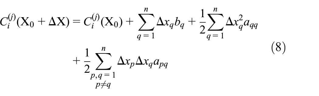
The equation (9) can be expressed in matrix form as follows.
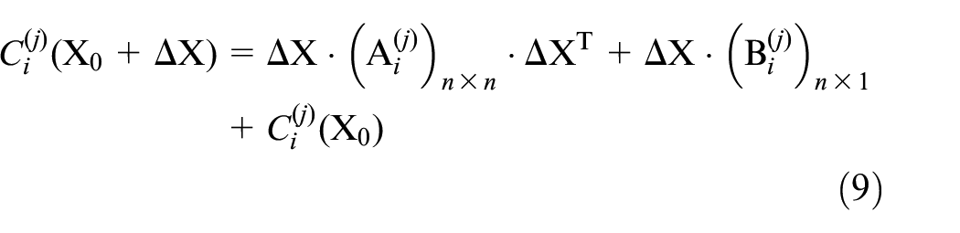
In the equation,
In any given field of view, equation (10) can be applied for each Zernike coefficient to establish a system of

Equation (10) represents a linear system of equations involving the unknown quadratic and linear coefficients. The least squares solution of the system, minimizing the Euclidean norm, is given by.

In equation (10),
Experiment
The experimental construction of the optomechanical virtual assembly systems
Virtual roaming technology in assembly environment
The preprocessing process for the model files is as follows: Firstly, the model files designed using industrial modeling software like UG are imported into the model rendering software such as 3DMax. Then, the model rendering software exports the model in the Fbx file format, which is compatible with editing in Unity3D software.
Realistically reproducing the observer’s perspective on characters in a virtual environment is a crucial aspect of virtual roaming technology. To accomplish this, the camera functionality of Unity3D software is employed. By scripting camera control, the perspective of the camera can be controlled to simulate the observer’s viewing process. Figure 8 illustrates the camera setup and actual effects of the first-person perspective camera and global perspective camera.

The camera setup and effects: (a) first-person perspective camera setup, (b) first-person perspective effect, (c) global perspective camera setup, and (d) global perspective effect.
Simulation of optomechanical system assembly process
Simulation of the assembly process is a crucial component of virtual assembly technology. This technology is utilized to establish a virtual assembly environment where the realistic assembly state of components can be accurately simulated. It aids in identifying potential collisions or interferences between the assembly site, environment, and other assembly components. Within the Unity3D software environment, the planned assembly process can be precisely replicated to generate a model, as depicted in Figure 9. For instance, let’s consider the interference analysis process of the front barrel assembly in the optical system.

Assembly path planning and pose setting for front mirror barrel.
The first step in assembling the front mirror barrel requires the development of an assembly path that aligns with the physical environment. Next, the key poses of the model are determined by considering the initial and final positions of the front mirror barrel along the assembly path. This can be achieved by duplicating the model in the scene and making appropriate adjustments to its position and orientation within the spatial coordinate system. After finalizing the assembly path and key poses, it is crucial to develop a model movement script that enables smooth transitions between poses, accurately simulating the actual assembly process.
During the assembly simulation process, it is crucial to detect collisions within the model to identify any potential interference with the surrounding environment. To visually represent the collision interference between the cube and the central mirror barrel, a color control script can be implemented. The primary goal of this script is to change the color of the central mirror barrel to red when a collision interference occurs between the two objects. The collision detection mechanism of the non-convex collider in Unity3D software activates when the cube mesh intersects with the central mirror barrel mesh, as illustrated in Figure 10.

Mesh intersection triggers collision detection.
Specific applications of Optomechanical virtual assembly system
Integration of virtual roaming technology and assembly verification technology into the optical-mechanical virtual assembly system necessitates the development of an operational interface that combines these functions to create an assembly operating system. Unity3D software provides the UI interface development function for this purpose. Figure 11(a) depicts the system function selection interface, which primarily consists of three components: virtual roaming, virtual assembly guidance, and misalignment error solving. The specific contents are as follows:
Virtual roaming function: virtual roaming involves simulating the operator’s perspective in the virtual assembly environment and enabling global roaming within the assembly environment. Figure 11(b) displays the virtual roaming operation interface.
Virtual assembly guidance function: the assembly process of optomechanical systems is complex and requires decomposing the intricate assembly sequence into relatively simple assembly procedures for verification. Once the final assembly process is determined, the assembly demonstration proceeds step by step for the distributed assembly procedures. Figure 11(b) showcases the assembly selection interface. After entering the assembly operation interface, as depicted in Figure 11(c), users can enter the selected assembly procedure by left-clicking the mouse. The “3D movie immersive assembly method” is employed to control the model assembly based on the actual project requirements. By clicking the start button, the model will be assembled according to the predetermined assembly sequence. During the process, users can click the pause or resume buttons to observe the model’s static state. After completing the model assembly, users can click the reset button to return the model to its initial position for redemonstration.
Misalignment error solving function: the precise misalignment of key components in the optical-mechanical system is determined by utilizing the proposed second-order sensitivity matrix solving algorithm and by inputting the detected Zernike coefficients. This approach ensures assembly accuracy.

Systems operation interface: (a) System startup interface, (b) Workshop virtual reality interface, (c) assembly selection interface, (d) assembly operation interface, and (e) misalignment error solving interface.
The provided technical roadmap outlines the steps involved in the development of an optomechanical virtual assembly system. Figure 12 demonstrates the efficacy of the virtual systems created based on this roadmap.

Visual demonstration of the virtual assembly systems for optomechanical devices: (a) operational scene 1, (b) operational scene 2, (c) operational scene 3, (d) operational scene 4, (e) operational scene 5, (f) operational scene 6, (g) operational scene 7, (h) operational scene 8, (i) operational scene 9.
Simulation experiment and actual adjustment results using the second-order sensitivity matrix method
Construction of simulation experiments
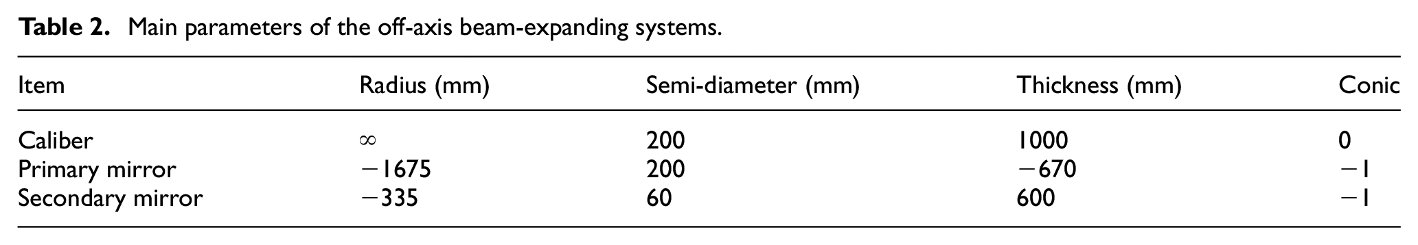
This simulation experiment will utilize an off-axis beam-expanding optical system as an illustrative example. The system’s specific parameters are provided in Table 2. Assumptions include the object being positioned at infinity, an off-axis distance of 280 mm for the caliber, and a light source wavelength of 630 nm. Figure 13 illustrates the two-dimensional layout diagram of the off-axis beam-expanding optical system.
Main parameters of the off-axis beam-expanding systems.

Two-dimensional layout diagram of the off-axis beam expander optical systems.
The purpose of this simulation experiment is to investigate the effects of eccentricity and tilt misalignment errors of the secondary mirror in the X and Y axes. The range of variation for the eccentricity error is −3 to 3 mm, and for the tilt error is −2 to 2 mrad. The image quality evaluation function for the off-axis expanded system involves the selection of the fourth to ninth coefficients of the Zernike polynomials. In order to conduct the experiment, 30,000 randomly sampled misalignment error samples are generated to solve the quadratic coefficient matrix and linear coefficient matrix in equation (10). Following that, 3000 sets of misalignment error samples are generated.
Analysis of simulation results
The mismatch quantities of the simulation model were determined using both the traditional sensitivity matrix method and the second-order sensitivity matrix method. A total of 3000 sets of mismatch error data were generated, and five sets of data were randomly selected for comparison. Table 3 presents the comparison between the calculated results using the traditional method and the true values, and Table 4 displays the comparison between the calculated results using the new method and the true values.
True values, calculated values, and errors using the traditional method.

True values, calculated values, and errors using the new method.

It is evident from Table 3 that the calculation accuracy of the conventional method decreases as the range of misalignment error increases, attributed to the linear approximation of Zernike coefficients and the misalignment error. Table 4 reveals that the new method achieves higher solution accuracy, even with larger ranges of misalignment error, as the error of the new method remains minimal. This indicates the superior calculation accuracy of the second-order sensitivity matrix method compared to the conventional method. To enable a more intuitive comparison of solution accuracy between these two methods, the Root Mean Square Error (RMSE) is calculated for 3000 sets of data and is also presented in Table 5.
Root mean square error comparison between the two methods.

Table 5 demonstrates that the RMSE values of the new method consistently exhibit lower values compared to the traditional method, implying a higher level of accuracy for the second-order sensitivity matrix method in contrast to the conventional sensitivity matrix method.
The actual calibration process and results
According to the aforementioned simulation process, the actual assembly layout schematic is designed as shown in Figure 14.

Layout diagram of off-axis two-mirror beam expander system.
During the system alignment process, the optical path is emitted from the interferometer and sequentially passes through the secondary mirror, main mirror, and then reflects upon reaching the standard mirror. The light is then reflected back to the interferometer through the main mirror and secondary mirror, enabling the measurement of the actual wavefront aberration information of the optical system. Subsequently, the second-order sensitivity matrix algorithm is utilized to address the misalignment of the secondary mirror components. The misalignment is then rectified by finely adjusting the secondary mirror components through the use of the secondary mirror adjustment stage.
Figure 15 depicts a realistic assembly environment that has been constructed based on the layout diagram shown in Figure 14.

Realistic alignment environment.
The results of detecting wavefront aberration in the system after rough alignment are showcased in Figure 16.

Wavefront aberration and Zernike coefficients of the system after rough alignment.
These results are presented in Table 6. The calculation results for the misalignment of the secondary mirror were obtained by substituting the Zernike coefficients obtained from the rough alignment detection into the improved sensitivity matrix model.
Calculated values of the misalignment of the secondary mirror.

The calculated misalignments were used to determine the Zernike coefficients. These coefficients were then compared with the alignment detection results obtained during the assembly process, as presented in Table 7.
Comparison of calculated and measured results for Zernike coefficients.

From the analysis presented in Table 7, it is evident that the Zernike coefficients obtained using the second-order sensitivity matrix method closely match those obtained from actual measurements. This close agreement between the calculated and actual results confirms the accuracy and reliability of the misalignments calculated using the second-order sensitivity matrix method.
In real alignment processes, various factors, such as airflow disturbances, instrument vibrations, and human measurement errors, can introduce interferences that lead to inaccuracies in the obtained Zernike coefficients from the interferometer. Consequently, these inaccuracies can amplify the error in the algorithmic solution for misalignment.
Moreover, the motion correlation among different components of the alignment system and the precision of the system itself directly impact the alignment results. Attaining the desired image quality through a single adjustment in real alignment processes can be challenging. It often requires multiple iterations of adjusting the compensation for misalignment using the secondary mirror adjustment platform.
The final system wavefront error is reduced to less than

The assembly results of the system after precision assembly using the second-order sensitivity method.
Conclusions and future work
This paper proposes a new method for assembling large aperture optomechanical systems. The method combines virtual assembly technology and misalignment error detection technology. The research findings are as follows:
The paper clarifies the core content of digital assembly technology and determines the technical roadmap for virtual roaming technology and assembly process simulation technology. The mathematical model principle of the second-order sensitivity matrix method is derived in detail.
The virtual assembly technology described in this paper enables virtual roaming of the optomechanical system assembly environment and simulation of the assembly process. A virtual assembly system for optomechanical systems is successfully constructed. The second-order sensitivity matrix method provides higher solution accuracy, as demonstrated by simulating an off-axis beam expander optomechanical system.
An actual off-axis beam expander assembly experiment is conducted, and the assembly results obtained after applying the second-order sensitivity matrix method are superior to
The process of assembling an opto-mechanical system is very complex and involves multiple disciplines, such as mechanics, optics, and adhesive processes. It requires interdisciplinary integration to ensure proper functionality. Although the virtual assembly system developed in this study only focuses on interference verification analysis of the assembly process of opto-mechanical system components, there are other factors that can affect the final quality of the system. These factors include tolerance control and component deformation during the assembly process.
It is essential to detect the assembly status of critical components in the optomechanical system in real-time and send the results to the virtual model to predict the final imaging quality. This allows for immediate feedback on the assembly results. Thus, developing a detection and control system that covers the entire opto-mechanical system assembly process, known as the digital twin technology, will be a crucial research direction in the future.
Footnotes
Handling Editor: Chenhui Liang
Declaration of conflicting interests
The author(s) declared no potential conflicts of interest with respect to the research, authorship, and/or publication of this article.
Funding
The author(s) received no financial support for the research, authorship, and/or publication of this article.