
Abstract
In the traditional method, as the loss product and gas are considered to be saturated, the heat leak of a cryogenic vessel is the latent heat of loss product. However, the temperature of loss product and gas exceeds the saturated temperature as measured in tests. Therefore, a portion of the heat leak is absorbed by the loss product when it diffuses into the gas phase of a cryogenic vessel in the storage process. In this study, the energy equations of the gas and liquid are established in cryogenic vessels during storage to investigate the actual heat leak of a cryogenic vessel in a storage process by considering the temperature distribution of the gas. Then, an experiment was conducted to demonstrate that the actual heat leak of a cryogenic vessel contains not only the latent heat but also the enthalpy change of the loss product, which is produced as it diffused into the gas phase. The results showed that the enthalpy change increased as the liquid level decreased and was critical for determining the actual heat leak in cryogenic vessels in the storage process, with a ratio of approximately 12% to the latent heat when the liquid level ratio is 85%.
Introduction
As cryogenic vessels can store more gas and have a lower working pressure than high-pressure gas cylinders, they are used by several facilities to store and transport diverse gases, such as liquid nitrogen, liquid oxygen, liquefied natural gas, and liquid hydrogen. The capacity of cryogenic vessels ranges from tens to hundreds of liters, and the pressure of the stored liquid is less than 1.5 MPa.1–3
Because the temperature of cryogenic liquids is below 120 K, they must be stored and transported in cryogenic vessels. The temperature difference is considerable between ambient and cryogenic liquids causing approximately 1.5%–2.0% of loss product daily from cryogenic liquids as the heat leak of cryogenic vessels even though they are super-insulated.4–6 For example, hydrogen is considered the next-generation energy due to its high calorific value and zero pollution. However, its storage temperature reaches 20 K, causing approximately 2.0%–3.0% of loss product daily. 7 The loss product of cryogenic vessels must be examined once a year to determine whether the thermal insulation performance fulfills the criteria of the standard and evaluate the thermal insulation performance and calculate the heat leak of cryogenic vessels.8,9 If the performance satisfies the standards, the cryogenic vessel can be safely used. Otherwise, it will require maintenance. The heat leak of cryogenic vessels have been investigated using the convection heat transfer to realize a semi-experiment and semi-analytical method that evaluate the heat leak using test data at a low liquid level to save the working medium. However, the error was approximately 10%. 10 If all the valves of a cryogenic vessel are closed during the storage and transit of cryogenic liquids, the pressure of the vessel continues to rise over time because of the heat leak, which is called self-pressurization. To explore the increasing rate of pressure, the self-pressurization process has been investigated at various liquid levels. Results showed that the increasing rate of the pressure is fast as the heat leak is considerable.11,12 The thermal insulation materials and structures of cryogenic vessels have been investigated to build the corresponding heat leak calculation model. Furthermore, their thermal insulation performances have been tested under various thicknesses, structures, and vacuum conditions to select the optimal structure and support the design of cryogenic vessels. 13
To model the heat leak at various liquid levels, numerical and experimental studies have investigated the heat transfer process of cryogenic vessels.14–20 A variety of computational fluid dynamics (CFD) models have been developed to precisely predict the heat leak and loss product during the storage process of cryogenic liquids. 14 For the optimization design of cryogenic vessels, the heat transfer of the insulation system and the phase shift of multiphase-thermal flow are modeled with high-fidelity physics CFD, demonstrating good agreement with the results of temperature profiles. 15 The heat leak of cryogenic containers has been experimentally tested at different liquid levels. The results indicated that the heat leak diminishes as the liquid level decreases. This implies that cryogenic liquids can be stored for a long time at low liquid levels.16,17 For large-scale liquefied natural gas tanks, an apparatus has been developed to investigate the effects of heat flux, liquid stratification, and mixture composition on cryogenic vessels. The results demonstrated that the loss product can be quantified as a function of heat fluxes, pressure, and liquid volume. 18 Some studies have employed CFD and experiment to investigate the heat exchange process in cryogenic vessels. The results showed that the gas is unsaturated, and its temperature rises as the height from the gas to gas–liquid interface rises.19,20
Based on the previous studies, the latent heat of the loss product was considered to represent the heat leak of cryogenic vessels, implying that the loss product is saturated and does not absorb any heat leak as it diffuses into the gas. However, CFD analysis and experiments show that the gas is not saturated, and its temperature exceeds the saturated temperature, indicating that the loss product is not saturated and absorbs heat as it diffuses into the gas of cryogenic vessel.
Therefore, the loss product diffuses from the gas–liquid interface to the gas phase causing its enthalpy change in the storage process of cryogenic vessels. In this study, we presented the actual heat leak of a cryogenic vessel during storage process by considering the diffusion of the loss product and the temperature distribution of the gas. In the following section, the heat transfer process is analyzed on a loss product test and storage process. Moreover, the energy equations of the gas and liquid are established to study the actual heat leak in cryogenic vessels, demonstrating that the actual heat leak comprised the enthalpy change and the latent heat of the loss product. In Section “Experiment,” an experiment is conducted, and the actual heat leak is calculated to confirm the findings that enthalpy change is an indispensable component, particularly at low liquid levels. Section “Results and discussion” shows that the enthalpy change of the loss product must be considered for determining the heat leak in cryogenic vessels besides the latent heat. Moreover, its ratio is approximately 12% to the latent heat when the liquid level ratio is 85%.
Physics model
Currently, the heat leak of cryogenic vessels is calculated to evaluate the thermal insulation performance that is the latent heat of the loss product in standards, such as ISO. 8 The loss product of cryogenic vessels is tested as follows. First, the pressure of cryogenic vessels matches the atmospheric pressure by discharging gas as the exhaust valve is open. Then, the test system requires 48 h to balance the pressure and temperature as the exhaust valve remains open. Finally, a mass flow meter is connected to the exhaust pipe behind the valve, and the loss product of cryogenic vessels is tested over 24 h. Figure 1 shows the test model. In the test process, the cryogenic vessel is filled with the cryogenic liquid and gas. Notably, the mass of the liquid can be determined by its liquid level gauge.

Experimental equipment of loss product test.
The following hypotheses are necessary to conduct the analysis mentioned in the following section:
(1) The liquid is saturated, and its temperature remains constant because the atmospheric pressure must be constant in the test process.
(2) The sole source of the heat leak in the cryogenic vessel is ambient.
(3) The liquid is incompressible as its density slightly changes in the test process.
(4) The gas temperature distribution inside the vessel is linear.
Heat transfer analysis
As shown in Figure 1, in the test process, the heat transfers from ambient to liquid and gas of the cryogenic vessel, causing part of the liquid to evaporate into gas to form the loss product at the gas–liquid interface. Then, the loss product flows out of the vessel and its volume rate is obtained by mass flow meter. The gas and liquid are the research objects, and their mass equation is expressed as follows10,11:

where ρg is the gas density, ρl is the liquid density, ρlp is the loss product density, which can be considered constant as the ambient temperature and pressure change slightly in test process, Vg is the gas volume, Vl is the liquid volume, and Vlp is the loss product volume.
In the test process, the heat leak is absorbed by the gas and liquid, while part of the liquid evaporates into gas to form the loss product. For energy conservation, the energy equation for the liquid and gas is expressed as follows15–17:

where eg is the special internal energy of the gas, el is the special internal energy of the liquid, QW is the heat leak into the cryogenic vessel from the ambient, and hlp is the special enthalpy of the loss product as it leaves the inner vessel.
According to the hypothesis, the liquid is incompressible. The first term in equation (2) can be expanded as

During the test, the mass of the liquid decreases as a portion of the liquid evaporates into gas to form the loss product, whereas the masses of the gas and loss product increase. These changes can be expressed as


where M is the mass rate of the evaporated liquid. According to equation (5), the evaporated liquid can be divided into two parts: the loss product and the increased gas occupying the volume of the evaporated liquid.
As the evaporated liquid is produced at the interface, its volume is occupied by the gas near the interface, where the gas temperature is equal to the saturated liquid temperature. Therefore, their relationships can be expressed as

where ρv is the saturated gas density. The internal energy can be expressed using its special heat capacity and temperature as follows:

where cv is the special heat capacity, and T is the temperature. By combining equations (4)–(7), equation (3) can be revised as follows:
Meanwhile, the enthalpy can be expressed as
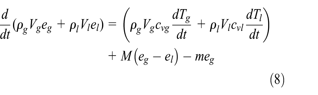
where p is the pressure. Therefore, according to equations (8) and (9), equation (2) can be rewritten as

where cvg is the gas specific heat capacity, cvl is the liquid specific heat capacity, Tg is the temperature of the gas in the cryogenic vessel, Tl is the temperature of the liquid in the cryogenic vessel, hv is the specific enthalpy of the saturated gas, L is the latent heat, expressed as L = hv–hl, and hl is the specific enthalpy of the saturated liquid.
In the test process of the loss product, as the test system is stable in temperature and pressure, the average gas temperature can be considered constant (i.e. dTg/dt = 0). Meanwhile, as a hypothesis, the liquid is saturated and its temperature is also constant (i.e. dTl/dt = 0). Based on these considerations, equation (10) can be simplified as follows:

where
During the storage process of cryogenic vessels, the evaporated liquid is generated at the gas–liquid interface and diffuses into the entire gas-phase space. Therefore, the temperature of the evaporated liquid can be defined as the average gas temperature of the entire gas phase. If the average gas temperature is set as Ta and the corresponding average enthalpy is ha, the actual heat leak absorbed by the evaporated liquid as it forms at the gas–liquid interface and diffuses into a gas, which can be expressed as follows:

Therefore, Ta must be obtained to calculate ha and evaluate the heat leak on equation (12).
As shown in Figure 2, we assume that the temperature of the gas is linearly distributed in the vessel as dT = adl, where a is the gas temperature gradient in the cryogenic vessel. Meanwhile the gas temperature Tv at the gas–liquid interface is consistent with the saturated liquid temperature. Therefore, the gas temperature Tg at a distance of l from the gas–liquid interface can be expressed as

According to the hypothesis, a is a constant and can be expressed as
where Tlp is the temperature of the gas under the head of the cryogenic vessel and l0 is the height of the gas–phase space in the cryogenic vessel. When the liquid level is Le, l0 = (1–Le) lt, where lt is the vessel length.
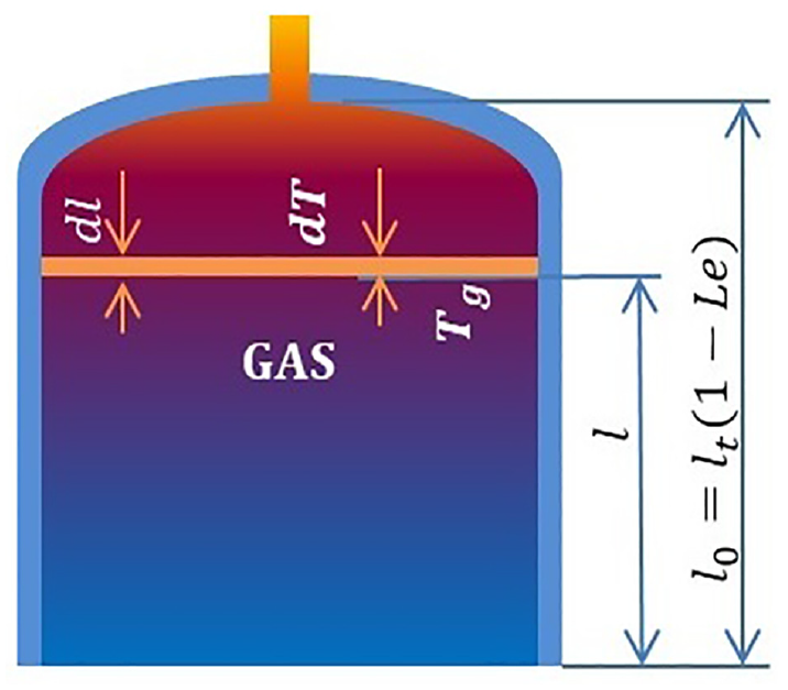
Gas temperature distribution.
The gas state equation can be used to express the gas density at any point in the gas–phase space as

where M0 is the molecular weight, pv is the pressure in the vessel, and R is the gas constant. Assuming that the gas is uniformly distributed in the horizontal direction in Figure 2, the gas mass in a small height direction dl is expressed as
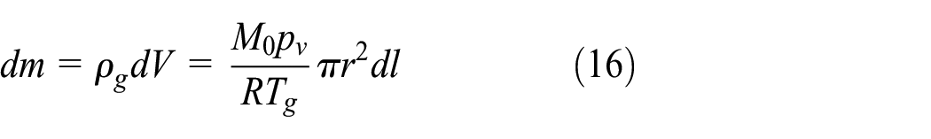
where r is the inner diameter of the vessel. According to equations (13) and (16), the gas mass in the cryogenic vessel is calculated as

The enthalpy can be expressed using the constant pressure specific heat capacity and the temperature. Therefore, the enthalpy of the gas dH can be expressed as

According to equation (18), the total enthalpy of the gas is calculated in the vessel as

Therefore, the average gas enthalpy ha is obtained as

The average gas temperature can be expressed as

Therefore, the values of ha and Ta can be obtained by equations (20) and (21). Then, the heat leak can be calculated using equation (12) in the storage process.
To analyze the difference between the actual heat leak and that obtained by the standard method, the actual heat leak of the cryogenic vessel can be divided into two parts in equation (12): the latent heat and the enthalpy change of the loss product, which are respectively expressed as
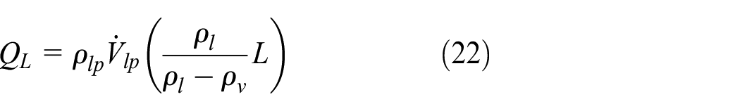

where QL is the latent heat of the loss product as the loss product absorbs heat leak and evaporates into gas, which is considered to be the heat leak of cryogenic vessels in the standard method, and QG is the enthalpy change of the loss product as the loss product diffuses from the interface to the gas volume in the storage process, which is ignored in the standard method. The enthalpy change of the loss product is determined by the average gas enthalpy, which is determined by the gas temperature.
Enthalpy change
In the loss product test, the saturated enthalpy of gas hv is constant and obtained by the thermophysical properties of the cryogenic liquid because the pressure of the cryogenic vessel matches atmospheric pressure that is almost constant. The parameter ha is proportional to Ta and obtained by the thermophysical properties of the gas on Ta. Then, the enthalpy change in the loss product is calculated.
If a significant volume of liquid is present in the cryogenic vessel, there is much cryogenic liquid in the cryogenic vessel. The liquid level is high and the actual heat leak of the cryogenic vessel is also high. However, there is small trace of gas in the cryogenic vessel, the average gas temperature Ta is low, and the enthalpy change of the loss product is also low at a high liquid level. If a few volume of liquid is present in the cryogenic vessel, there is a small amount of cryogenic liquid in the cryogenic vessel. The liquid level is low and the actual heat leak of the cryogenic vessel is also low. However, there is much gas in the cryogenic vessel, the average gas temperature Ta is high and the enthalpy change of the loss product is also high at a low liquid level. Meanwhile, whether the liquid level is high or not, the average gas temperature exceeds the saturated temperature in the cryogenic vessel.
Experiment
The experimental equipment was designed to measure the loss product, as shown in Figures 1 and 3. The medium was liquid nitrogen. The cryogenic vessel has a volume of 180 L. The inner and outer walls were made of SA 304. The inner vessel has a diameter of 450 mm and a length of 950 mm, and the elliptical head had a height of 130 mm. Multiple layers of insulating materials were present in the vacuum interlayer. A pressurized tank is thermally insulated by vacuum at approximately 1.0 × 10⁻² Pa. The loss product test was completed according to ISO standards at various liquid levels to explore the heat leak of the cryogenic vessel. 20 The tests selected three different initial liquid level ratios: 51.4%, 70.2%, and 86.1%. There were 17 thermocouples set up in the center of the vessel to collect the temperature and obtain the temperature distribution in the cryogenic vessel. To improve measurement accuracy, thermocouples must be calibrated before use. The initial quantity of the liquid could be determined using the liquid level gauge. Liquid nitrogen enters the cryogenic vessel through the liquid inlet valve, while the mass flow meter is mounted at the exhaust valve.

Sketch of the cryogenic vessel under test.
The loss products and their temperatures were examined at three different liquid levels. Figures 4 and 5 show the test results.
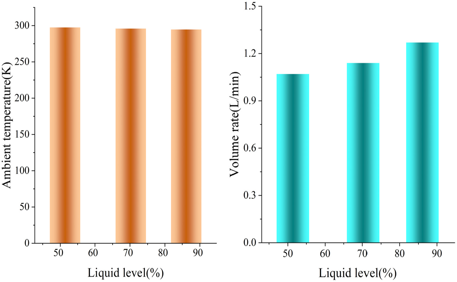
Ambient temperature and volume rate in test.

Gas temperature distribution in tested cryogenic vessel.
Figure 4 illustrates the ambient temperature and volume rate. The ambient temperature is almost constant, and the volume rate of the loss product rises as the liquid level rises in the test. This means that the loss product is high when the liquid level is high.
Figure 5 shows the gas temperature distribution in the test. The gas temperature increases as its distance increases to the gas–liquid interface. The gas temperature under the head of the cryogenic vessel decreases as the liquid level rises, indicating that the enthalpy change also decreases as the liquid level rises. This suggests that the enthalpy change absorbed only a small fraction of the heat leak at a high liquid level.
Results and discussion
Equations (11)–(23) are used to determine the parameters a, Ta, QL, QG, QW, and ratios of the enthalpy change and latent heat to the actual heat leak based on the data in Figures 3 and 4. Figures 5 to 7 summarize the findings.
Figure 6 shows a and Ta in the test. The parameter a increases as the liquid level rises, whereas Ta decreases. These indicate that the Ta is low at a high liquid level because of the large amount of liquid nitrogen in cryogenic vessel. Simultaneously, the temperature of the liquid nitrogen is the lowest in the system, which causes the average temperature of gas in cryogenic vessel is low, whereas a is high, indicating that the gas has a small volume but the temperature greatly decreases.

Gas temperature gradient and average gas temperature.
Figure 7 shows the enthalpy change, latent heat of the loss product, and actual heat leak of the cryogenic vessel in the test. Figure 8 presents the ratios of the enthalpy change and latent heat to the actual heat leak.

Heat leak at different liquid levels.
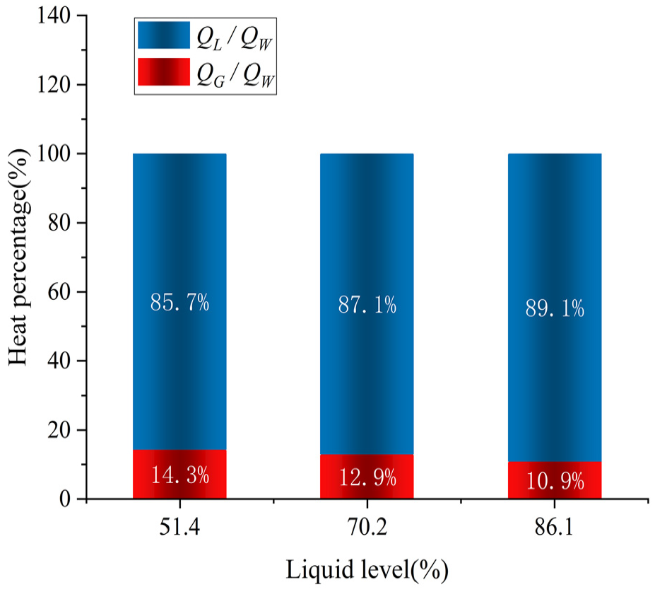
Proportion of latent heat and enthalpy change.
Figures 7 and 8 show that QW exceeds the QL of the loss product. At a 51.4% liquid level, the actual heat leak was 4.27 W, the latent heat was 3.66 W, and the enthalpy change was 0.61 W, and its percentage of the actual heat leak was 14.3%. However, an enthalpy change of 0.61 W was omitted in the current test method. Thus, enthalpy change is an important component of heat leak for cryogenic vessels. At an 86.1% liquid level, the actual heat leak was 4.51 W, the latent heat was 4.02 W, and the enthalpy change was 0.49 W, and its percentage of the actual heat leak was 10.9%, which was less than 0.61 and 0.57 W at 51.4% and 70. 2% liquid level, respectively. Therefore, the enthalpy change decreases as the liquid level increases. In addition, the actual heat leak was 4.51 W at an 86.1% liquid level, which exceeded 4.27 W at a 51.4% liquid level. This agrees with the previous analysis that the actual heat leak rises as the liquid level rise. These findings suggest that both the actual heat leak and latent heat rise as the liquid level rises, whereas the enthalpy change decreases. Notably, the enthalpy change is an important component of the total heat leak and should not be overlooked during cryogenic vessels storage.
These results demonstrated that the heat leak in the current method cannot reflect the real thermal insulation performance of the tested cryogenic vessel if the enthalpy change of the loss product is ignored. The enthalpy change of the loss product is determined by Ta, which decreases as the liquid level increases because gas occupy less volume and its temperature is low at a high liquid level, causing QG to decrease, whereas QL and QW both increase as the liquid level rises.
Conclusions
The following conclusions can be derived based on the tests and the discussion of the actual heat leak in a cryogenic vessel during the storage process:
(1) The actual heat leak of the cryogenic vessel during the storage process could be separated into two parts: the latent heat and the enthalpy change of the loss product.
(2) The enthalpy change occurred when the evaporated liquid diffused from the gas–liquid interface to the gas phase space of the cryogenic vessel during storage process.
(3) The enthalpy change was reduced because the average gas temperature dropped as the liquid level increased.
Footnotes
Appendix
Notation

| ρg | gas density | kg/m3 |
| ρl | liquid density | kg/m3 |
| ρlp | loss product density | kg/m3 |
| ρv | saturated gas density | kg/m3 |
| cv | special heat capacity | kJ/(kg K) |
| cvg | gas specific heat capacity | kJ/(kg K) |
| cvl | liquid specific heat capacity | kJ/(kg K) |
| eg | special internal energy of the gas | kJ/kg |
| el | special internal energy of the liquid | kJ/kg |
| p | pressure | Pa |
| pv | pressure in the vessel | Pa |
| QW | heat leak into the cryogenic vessel | W |
| QL | latent heat of the loss product | W |
| QG | enthalpy change of the loss product | W |
| hlp | special enthalpy of the loss product | kJ/kg |
| hv | specific enthalpy of the saturated gas | kJ/kg |
| hl | specific enthalpy of the saturated liquid | kJ/kg |
| ha | average gas enthalpy | kJ/kg |
| H | enthalpy of the gas | kJ |
| l | height | cm |
| L | latent heat | kJ/kg |
| M | mass rate of evaporated liquid | kg |
| M 0 | molecular weight | g/mol |
| r | inner diameter of the vessel | cm |
| R | gas constant | J/(mol K) |
| T | temperature | K |
| Tg | temperature of the gas | K |
| Tv | saturated gas temperature | K |
| Tl | temperature of the liquid | K |
| Ta | average gas temperature | K |
| Vg | gas volume | L |
| Vl | liquid volume | L |
| Vlp | loss product volume | L |
Handling Editor: Chenhui Liang
Declaration of conflicting interests
The author(s) declared no potential conflicts of interest with respect to the research, authorship, and/or publication of this article.
Funding
The author(s) disclosed receipt of the following financial support for the research, authorship, and/or publication of this article: This work received funding [Gansu National Science Foundation in China] under Grant Agreement No [23JRRA1352].