
Abstract
As a necessary support system of high-speed rotor system, the roller bearing with elastic support’s vibration characteristics directly affect the stability and safety of rotor system. At this point, the theoretical analysis of bearing performance under the assumption of rigid ring is obviously no longer applicable. In this paper, considering the elastic deformation of both cylindrical roller bearing outer ring and the groove elastic support, the dynamic differential equations of cylindrical roller bearing with the elastic support are established on the basis of rolling bearing dynamics, and the bearing’s vibration under different working conditions is analyzed. The theoretical analysis results show that the groove elastic support can effectively reduce the radial vibration of cylindrical roller bearing under high speed and large radial load. And the experimental results show that the test’s vibration is consistent with the simulation’s vibration, which proves the reliability of the dynamic model of cylindrical roller bearing with the groove elastic support proposed in this paper. This research gives a new method for improving the dynamic characteristics of high-speed cylindrical roller bearings, and the model presented in this paper provides a theoretical basis for the design and manufacture of cylindrical roller bearing with elastic support.
Keywords
Introduction
As the main part of aero-engine spindle, high-speed CRB usually is used with elastic support for reducing the natural frequency of the system. For the lightweight and compact design of the whole engine system, the bearing rings are getting thinner, even the bearing and elastic support are processed into a component, called bearing integration. At this point, as CRB under elastic support, the hypothesis of bearing’s rigid ring is no longer valid. In other words, the deformation of the bearing ring with elastic support cannot be ignored, 1 which have some effects on the bearing load distribution, that in turn influences dynamic characteristics, such as bearing’s vibration. Bearing vibration is one of the criteria to measure its stability and the evaluation indexes of bearings. So, in order to improve the stability of bearing operation, many researchers have conducted extensive studies on the vibration characteristics of CRB:
Chun et al. 2 pointed out that CRB, which even has no machining error and good lubrication, still has vibration and noise caused by their structural characteristics. Therefore, many scholars have carried out a series of studies on the influence of CRB components on its vibration. The roller, which produces the fundamental frequency of the roller bearing, directly affects the bearing vibration.
Nakai et al. 3 measured the frequency and amplitude of CRB’s howling and pointed out that the howling frequency was consistent with the natural frequency of a single roller. Based on Hertz contact theory, Sharma et al. 4 established a dynamic model of CRB, and analyzed the influence of the roller number on the vibration characteristics of the CRB by Pointcaré diagram. In addition, researchers had point out hollow rollers also can change CRB dynamic characteristics5–7 gave an analytical dynamic model of a lubricated hollow CRB and analyzed the influences of the radial load, the shaft speed, and the hollowness percentage of the roller on the bearing vibrations. Different roller modification is also one of the factors affecting bearing vibration. Based on the finite element model of CRBs, Yan, and Yang 8 studied the influence of roller modification on the vibration characteristics of CRB, and the research results showed that the tangential arc modification of rollers can reduce the radial vibration of CRB. Considering the eccentricity produced by roller processing, Cui et al. 9 gave a nonlinear dynamic differential equations of high-speed CRB, considering the impact of roller dynamic unbalance, and found roller dynamic unbalance can affect the state of the cage motion and cause the cage’s vibration acceleration level to increase.
Cage is one wearing part of high-speed CRB, and its effect on CRB vibration is also the focus of research. Considering centrifugal force and raceway contact force influence on the deformation of bearing raceway, Leblanc et al. 10 established a high-speed CRB dynamics differential equation, and analyzed the effects of the cage eccentric force on vibration frequency of inner ring and the cage mass center. The research found, considering the raceway deformation of CRB, the inner ring, and cage work more stably. Collision between roller and cage pocket 11 is one of the causes of bearing vibration. Chen et al., 12 based on chaos theory, studied the influence of high speed CRB’s cage eccentricity and guiding clearance on cage vibration, and the result showed that the cage eccentricity and guiding clearance had significant influence on cage vibration.
Many study13–15 found the lubricating oil property also affect CRB vibration by theoretical and experimental method, and provided the vibration of CRB under different operating condition. Hao et al. 16 built a single disk two fulcrum rotor bearing system test-bed and found that with the increase of ubricating oil temperature, the peak-peak value, and effective value of bearing vibration increase obviously. Berger 17 experimentally measured the cage vibration of CRB at low temperature and then pointed out that the lack of lubrication at low temperature is the main cause of cage vibration.
The defects of CRB also can cause bearing’s vibration.18–20 Liu and Wang 20 presents a time-varying stiffness excitation model for a CRB including a local fault with the roughness surface based on Greenwood and Williamson’s method and analyzed the effects of the roughness and local fault on vibrations of CRB. The result found the roughness surface can greatly affect vibrations for CRB under a small force. But its effect will decrease with the increment of radial load, which will close to the value of smooth CRB.
The elastic deformation of the bearing ring will certainly affect its performance,21–23 but there are few researches on its effect on bearing vibration. Alexandre et al., 24 based on the dynamics of high-speed CRBs, found that the flexible ring can reduce the high frequency harmonic vibration of bearings.
Bearing vibration will also be affected by working conditions, which is very important for the practical application of bearings. Shi and Liu 25 presented an improved planar dynamic model for calculating the vibrations of CRB, and found that the vibration accelerations of the rings, rollers, and cage increase with the increments of the shaft speed and the radial load.
The above researches on rolling bearing are carried out on the basis of rigid support assumption. When the support is elastic, under the load, the elastic support or damper installed on the rolling bearing will have elastic deformation which affects the collision and forces inside bearing, even the number of loaded rolling ellement. So, the bearing will show different dynamic characteristics. Based on the dynamics theory of rolling bearing and the modal synthesis method, Xia et al. 26 established a bearing/rigid rotor model supported by the cylindrical roller bearing with elastic support and squeeze film damper, and analyzed the effects of rotating speed, unbalance of rotor, and structure parameters of squeeze film damper on the sliding of cylindrical roller bearing cage. Mao and Wang 27 proposed rolling bearing squirrel-cage flexible support ball bearing quasi-dynamic iterative Finite Element Model, and found integrated squirrel-cage flexible support can increase the bearing’s fatigue lifetime. Peng and Gao 28 pointed out that low stiffness elastic support can reduce the vibration of high-speed rolling bearings, but this paper did not give the concrete relation between elastic support and bearing vibration. Xie et al. 29 found that the additional elastic support (damping ring) can reduce the vibration of ultra-high speed miniature ball bearings both through simulation and experimental methods. In addition, its high-speed performance is obviously better than that of ordinary bearings. Wu et al. 30 gave a load structure seismic rolling bearing based on viscoelastic damping element, but it just is a patent and no relevant research articles has been published.
Because elastic supports are used in few applications, mainly in aero-engine spindles to reduce critical speed, and most of the research literature on elastic supports takes rotor support system as the research object, mainly analyzing the dynamic characteristics of rotor under elastic support,31–34 there are few studies on the impact of elastic supports on rolling bearing dynamics.
Therefore, dynamic analysis of cylindrical roller bearing supported by GES is presented in this paper. Considering the elastic deformation of outer ring and GES, and based on roller bearing dynamic theory, the dynamic analysis model of cylindrical roller bearing with GES was established. Then, the influence of structural parameters of elastic supporting parts and bearing operating parameters on bearing vibration characteristics were analyzed. The results in this paper can provide a theoretical basis for the structural design and application of GES to improve CRB vibration characteristics.
GES structure and installation method
The elastic support is named GES which is a cylinder slotted along the circumference formed a number of grooves and arc beams. Figure 1 is the GES structure diagram. In Figure 1(a), H is arc beam thickness, H’ is groove gap, α is transition angular, A point and B point are the ends of an arc beam, ε p is the azimuth of the pth arc beam, Di and Do are the inner and outer diameters of GES, respectively.
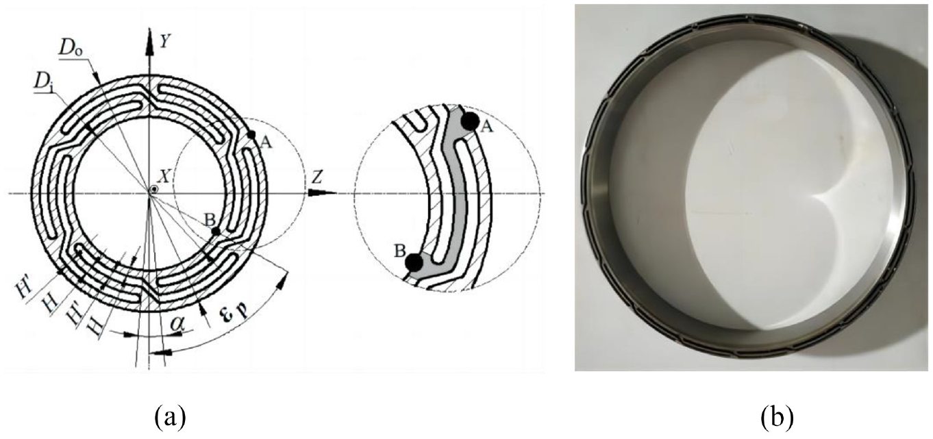
Structure of GES: (a) schematic structure of GES and (b) picture of GES.
The assembly diagram of GES is shown in Figure 2. The GES is mounted between the house and CRB’s outer ring. In working condition, inner ring of CRB rotates, outer ring of CRB does not rotate, but can translate in the radial plane because of GES elastic deformation under radial load. In Figure 2, {O; X, Y, Z} is the inertial coordinate system fixed in space, {or;xr, yr,zr} is the roller center coordinate system, {oi;xi,yi,zi} is the inner ring center coordinate system, {oc;xc,yc,zc} is the cage center coordinate system, {op;xp,yp,zp} is the cage pocket coordinate system, {oo; xo,yo,zo} is the outer ring center coordinate system.
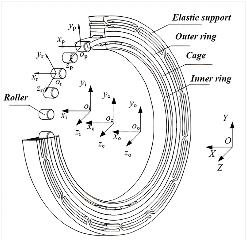
Assembly diagram of GES.
Differential equations of BES
The dynamic differential equations of roller, cage, inner ring, and outer ring are established by analyzing the interaction forces of each part of BES.
Dynamic differential equations of roller dynamics
When the CRB is running at high speed, the movement of the roller is affected by the joint action of inner and outer rings and cage. The roller force diagram is shown in Figure 3.
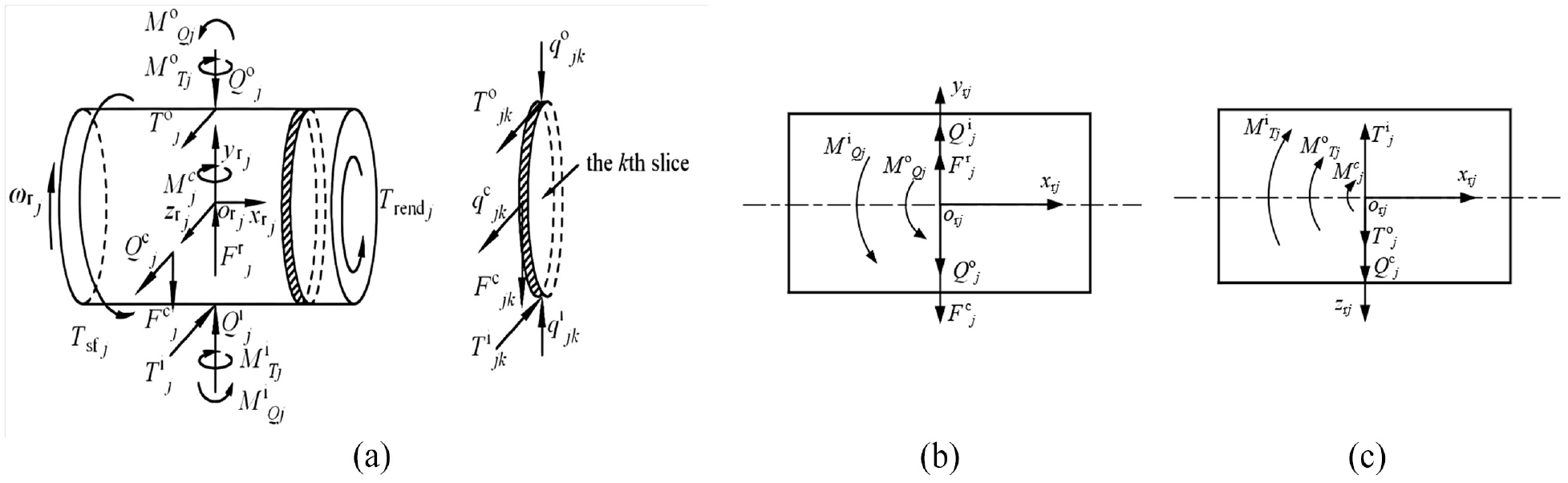
Roller forces diagram: (a) three-dimensional diagram, (b) the projection in x-y plane, and (c) the projection in the x-z plane.
In Figure 3, Qi j and Qo j are the Hertz contact forces between the jth roller and the raceway of the inner and outer rings respectively. Qc j is the normal force between the jth roller and the cage beam; Fr j is the centrifugal force of the jth roller; Fc j is oil film drag force between roller and cage beam; Ti j and To j are the towing forces of the lubricating oil film between the jth roller and the inner and outer raceway respectively. Mi Qj and Mo Qj are the additional torques generated by the contact force between the jth roller and the inner and outer raceway due to roller tilt; Mc j is the additional torque generated by the tangential force Fc j between the jth roller and the cage; Mi Tj and Mo Tj are the additional force moments generated by the oil film drag power between the jth roller and the inner and outer raceway due to roller tilt. qi jk and qo jk are the contact forces between the kth slice of the jth roller and the inner and outer raceways respectively. qc jk is the normal force between the kth slice on the jth roller and the beam of the cage; Ti jk and To jk are respectively the dragging power of the lubricating oil film of the kth slice of the jth roller and the inner and outer raceway; Fc jk is the drag force of lubricating oil film between the kth slice on the jth roller and the cross beam of cage hole. Tsfj and Trendj are respectively the blocking torque of lubricating oil on the surface and end face of the jth roller. The calculation formulas of all the above forces refer to the book by Deng and Jia. 35
Through the force analysis of roller, the differential equations of roller dynamics can be written as equation (1).

In equation (1), mr is the roller mass; Jr
xj
, Jr
yj
, Jr
zj
is rotational inertia of the jth roller in the inertial coordinate system {O; X, Y, Z};
Dynamic differential equations of cage
In high-speed working condition, the CRB’s cage is not only subjected to the force of the guide ring and the roller, but also subjected to the resistance of oil and gas mixture due to the shear action of the cage. 35 The cage force diagram is shown in Figure 4.

Cage force diagram.
In Figure 4, ec is the eccentricity of the cage center relative to the bearing outer ring center; ψc is the azimuth of the cage between the center coordinate system of the cage {oc; xc,yc,zc} and central coordinate system of outer ring {oo; xo, yo, zo}; ωc is the rotating speed of the cage; F’cy, F’cz and Mcx are the forces between the cage guide surface and the cage centering surface; Mco is the blocking force moment on the surface and side of the cage, and Fcr is the centrifugal force of the cage. The calculations of all the above forces refer to the book by Deng and Jia. 35
Through the analysis of cage force, the differential equations of cage dynamics can be written as equation (2).

In equation (2), mc is the cage mass; dm is the bearing pitch circle radius; Jcx, Jcy, Jcz are the inertia moment of cage in coordinates {O; X, Y, Z};
Dynamic differential equations of inner ring
Because the inner ring is only affected by the roller and the lubricating oil, combined with the Figure 3, the dynamic differential equation of inner ring is obtained.

In equation (3), mi is the inner ring mass; Fr is the radial force applied to the inner ring; Jyj, Jzj are the inertia moment of inner ring in the coordinate system {O; X, Y, Z};
Dynamic model of outer ring
Reaction force of GES
Under radial load, the GES will deform. The Figure 5 gives the deformation and forces diagram of the GES’s pth arc beam.

Deformation and forces diagram of the GES’s pth arc beam: (a) deformation diagram of the pth arc beam and (b) forces diagram of the pth arc beam.
In Figure 5, under radial load, the point B of the arc beam end moves to point B’, and the displacement is Δ p ; ap and bp are the components of B’s displacement Δ p in the arc beam center local coordinate system {ξp,Cp,ηp}. According to the geometric relationship in Figure 5, it can be obtained: ap = Δ p sinβp, bp = Δpcosβp. ηs is the elastic center of arc beam. 36 The symbolic expressions of Δ p and βp can be found in the appendix. εp is the azimuth of the pth arc beam. R is radius of the arc beam. ϕ is span angle of arc beam. δ is the displacement of GES’s center. φ is the included angle between the tangent of an arbitrary point on arc beam and the chord of arc beam. s is the arc length, θ is the center angle of s.
Assuming that there is no angular displacement at the A and B ends of the arc beam, according to the elastic center method in Xiao and Zhang, 36 the internal forces fξp, fηp and Mp of the pth arc beam in Figure 5 are as follows:

In equation (4), μ is the material shear coefficient, E is the elastic modulus of the material, I is the moment of inertia of the beam cross-section, ξ and η are the coordinates of any point of the circular beam in the local coordinate system {ξp,Cp,ηp}, ds is the arc length of any section of the arc beam, As is the cross-sectional area of the arc beam AB.
According equation (4), the net force of n arc beams are the reaction force of GES, which component in the coordinate system{Y, O, Z} can be written as:

Because the outer ring of CRB does not rotate in the radial plane as CRB runs, the moment is not taken into account in the equation (4).
Dynamic differential equations of outer ring
The outer ring of BES is affected not only by the force of roller and cage, but also by the reaction force (Fy, Fz) of GES in the radial plane. Because the outer ring does not rotate, only translates, the force balance equation of the outer ring along the two coordinate axes is established. Figure 6 shows the force diagram for the outer ring.
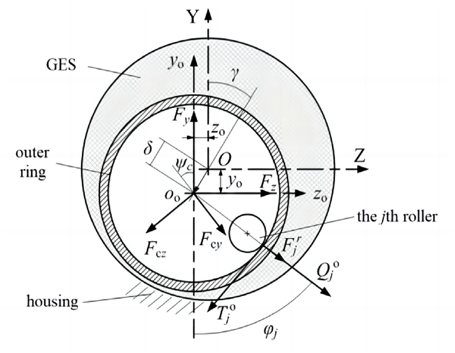
Outer ring force diagram.
Through the force analysis of outer ring, the differential equations of outer ring dynamics can be written as equation (6).

In equation (6), mo is the outer ring mass;
Results and discussion
The dynamics differential equations (equations (1), (3), and (6)) of BES considering outer ring’s flexibility are solved by GSTIFF (Gear Stiff) integer algorithm with variable step, and dynamic motion parameters of CRB can be obtained. Here, the radial acceleration level of inner ring was used for evaluating CRB’s vibration by acceleration level method. The calculation formula of radial acceleration level is as follows:

In equation (7), dB is vibration acceleration level value, a is the RMS of bearing vibration acceleration; a0 is the reference acceleration (a0 = 9.81 × 10⁻³ m/s2).
This paper focus on analyzing the impact of structural parameters and working conditions on vibration of CRB’s inner ring. The main structure parameters of CRB and GES are shown in Table 1.
Main parameters of CRB and GES.

Influence of GES’s structural parameters on CRB vibration
In section 4.1, the inner ring speed of CRB is 10000 r/min, and the radial load applied to the bearing inner ring is 1000 N.
Influence of the arc beam number n of GES on CRB vibration
Figure 7 shows the relationship between the n of GES and CRB’s radial acceleration level and FFT plot (vibration spectrum). In Figure 7(b), fvc is the fundamental frequency of bearing vibration (the same below), which is RN times the rotational frequence of bearing cage.

Impact of arc beam number n of GES on CRB vibration: (a) radial acceleration level and (b) FFT plot.
In Figure 7, with the increase of n, bearing vibration value and the amplitude of fvc, 2fvc, 3fvc, 4fvc… present firstly decreases and then increases. When n is 24, the bearing vibration value and the amplitude of fvc, 2fvc, 3fvc, 4fvc… are minimal. Obviously, the vibration of BES is smaller than that of BRS. So, it can be concluded that GES significantly reduces vibration of CRB. In addition, it can be found in Figure 7(b), that fvc of BES is larger than that of BRS. It is because BES has more loaded roller than BRS, cage slip ratio of BES is lower, so fvc of BES is higher.
Impact of arc beam thickness H of GES on CRB vibration
Figure 8 shows the relation of arc beam thickness H of GES and CRB’s radial acceleration level and FFT plot.

Impact of arc beam thickness H of GES on CRB vibration: (a) radial acceleration level and (b) FFT plot.
In Figure 8(a), when n is 24, 28, and 32, the CRB vibration increases with the increase of H. When n is 16 and 20, with the increase of H, the CRB vibration decreases first and then increase. When n is 24, H is 0.4 mm, BES has the minimum vibration value. Figure 8(b) presents the relationship between H and CRB vibration spectrum when n of GES is 24. The bearing vibration’s amplitudes of fvc, 2fvc, 3fvc, 4fvc… decrease first and then increase with H, which has the same trend with Figure 8(a) when n of GES is 24. Comparing with Figure 7, H has less effect on bearing vibration than n.
Impact of groove gap H’ of GES on CRB vibration
Figure 9 shows the relation of groove gap H’ of GES and CRB’s radial acceleration level and FFT plot.

Impact of groove gap H’ of GES on CRB vibration: (a) radial acceleration level, and (b) FFT plot.
It can be seen from Figure 9(a) that as H’ of GES increases, the bearing vibration decreases slightly, which means H’ of GES has small effect on the vibration of the CRB. When n is 24 and H’ is 1.2 mm, bearing vibration is the minimum. Figure 9(b) shows the relationship between H’ of GES and bearing FFT plot when n of GES is 24. The amplitudes of fvc, 2fvc, 3fvc, 4fvc… has slight drops with H’, which is the same trend with Figure 9(a) as n of GES is 24. It can be seen from Figure 9(b), H’ of GES has little influence on the amplitude of each octave of bearing vibration, which also illustrates that H’ of GES has no significant effect on reducing bearing vibration.
Impact of transition angular α of GES on CRB vibration
Figure 10 shows the relation of transition angular α of GES and CRB’s radial acceleration level and FFT plot.
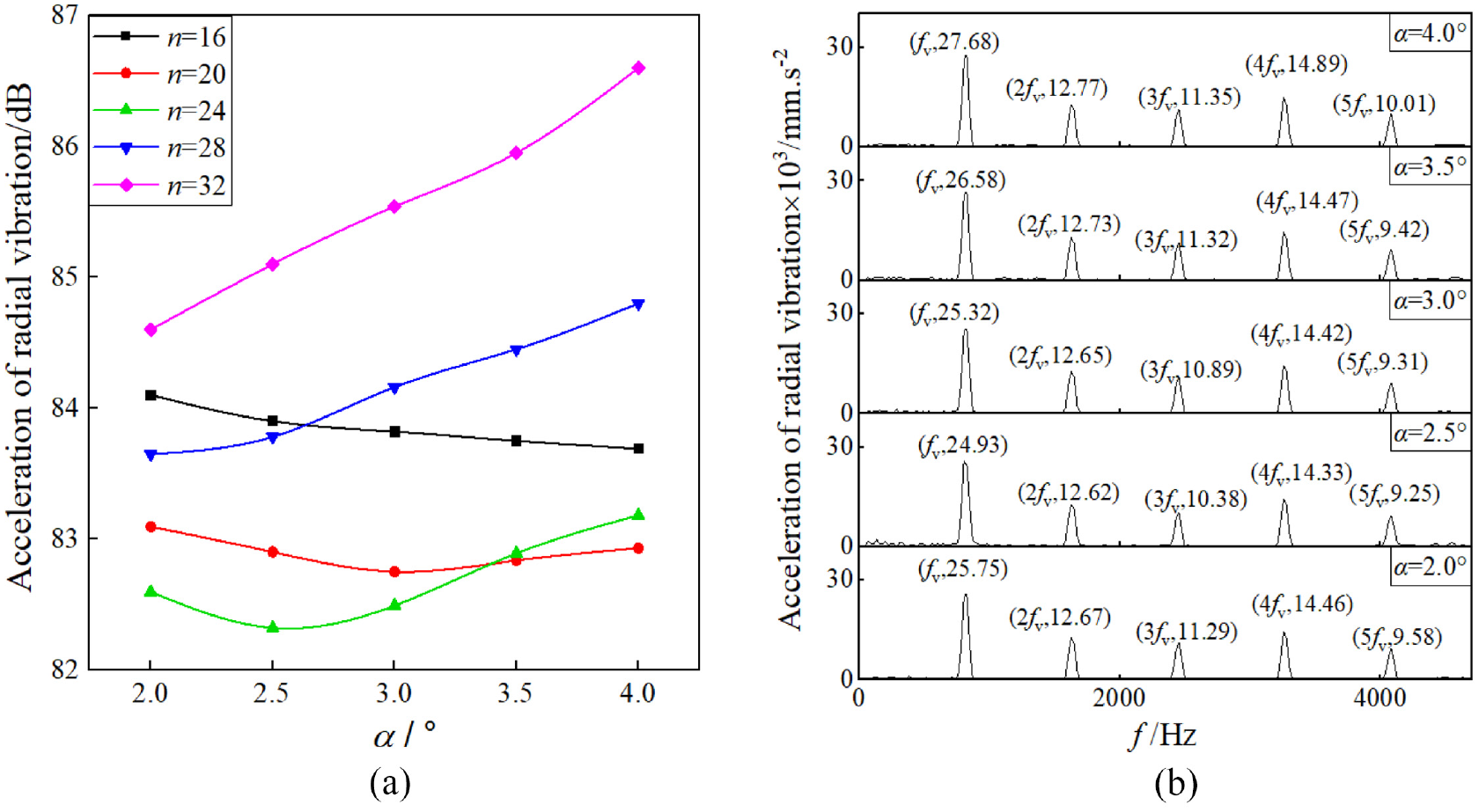
Impact of transition angular α of GES on CRB vibration: (a) radial acceleration level, and (b) FFT plot.
In Figure 10(a), when n is 16, with the increase of α, the CRB vibration gradually decreases with a small range. When n is 20 and 24, with the increase of α, the bearing vibration increases first and then decrease. When n is 28 and 32, with the increase of α, the bearing vibration increases. When n is 24, α is 2.5°, BES has the minimum vibration value. Figure 10(b) presents the relationship between α of GES and bearing FFT plot when n of GES is 24. The bearing vibration’s amplitudes of fvc, 2fvc, 3fvc, 4fvc… decrease first and then increase with α, which is the same trend with Figure 10(a) when n of GES is 24. Comparing with Figures 8 and 9, it indicates that α has more effect on bearing vibration than H’ but less effect on bearing vibration than H.
Through the above analysis of the impact of GES’s structure parameters on CRB vibration, it can be concluded that the GES can effectively suppress the CRB vibration. More over, n has the most significant effect on CRB vibration, followed by H, α. H’ have the least obvious effect on that.
Impact of operating condition of GES on CRB vibration
Impact of radial force (Fr) on CRB vibration
Figure 11 presents the relationship between Fr and vibration of the BES and BRS when the bearing is running at 10,000 r/min. The structural parameters of CRB and GES are the same as those in Table 1.

Impact radial force Fr on radial acceleration level of CRB.
According to Figure 11, when Fr is between 800 N and 2000 N, the vibration of BES is lower than BRS. As n is 24, the vibration value of bearing is basically at the lowest value, and compared with BRS, when Fr is 1400 N, the maximum reduction is 16.4%. When Fr is between 600 N and 800 N, it is not obvious that GES reduces the vibration of CRB. However, when Fr is lower than 600 N, and n is 16 and 20, the vibration of BES is higher than that of BRS. The results show that GES can reduce vibration of CRB effectively over a wide range of loads. But, when n is small and loads is very low, it is not significant that GES suppresses CRB vibration, even CRB vibration is intensified.
Impact of rotation speed(r) on CRB vibration
Figure 12 shows the vibration of the BES and BRS at different rotation speed, when the radial load Fr on CRB is 1000 N.

Impact rotation speed r on radial acceleration level of CRB.
It can been seen from Figure 12, when the speed r is bigger than 8000 r/min, vibration of BES is significantly lower than that of BRS. When the speed r is lower than 8000 r/min, vibration of BES is was close to that of BRS. Moreover, as the speed is bigger than 10,000 r/min and n is 24, BES keeps the vibration at a minimum. Therefore, GES can reduce roller bearing’s vibration at high speed and can’t control the vibration at low speed. So, according working condition, reasonable selection of GES structural parameters can reduce bearing vibration to the greatest extent.
Test verification
In order to verify the correctness of the theoretical model in this paper, the rig in Figure 13 was used to test the dynamic characteristics of bearing. Figure 13 shows the internal structure of testing rig. The parameters of testing bearing were shown in Table 1. Because the designed rotation speed of the test shaft is below 12,000 r/min, so the test rotation speed is smaller than 12,000 r/min to protect the test rig.
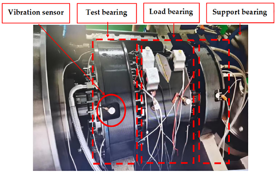
Test rig of CRB with GES.
Impact of arc beam number n of GES on CRB vibration
Figure 14 is the comparison diagram of CRB vibration values obtained by theoretical calculation and test when arc beam number n of GES is different. In Figure 14, Theory denotes the theory results, and Experiment denotes the experiment results. The radial force Fr acted on CRB is 1000 N.

Impact of arc beam number n of GES on CRB vibration: (a) 9000 r/min and (b) 10,000 r/min.
In Figure 14, the experimental results show that GES can effectively reduce the vibration of CRB, which is consistent with the theoretical analysis results. The bearing vibration measured in the test decreases first and then increases with the increase of n, which is the same with the theoretical calculation results, and the maximum relative error of results obtained by two methods does not exceed 5%.
Impact of working conditions on BES vibration
Figures 15 and 16 show the impact of rotation speed r and radial force Fr on BES vibration respectively. In Figure 15, Fr of CRB is 1000 N. In Figure 16, r of inner ring is 10,000 r/min.

Impact of rotation speed r on BES vibration: (a) n = 16, and (b) n = 32.

Impact of radial force Fr on BES vibration: (a) n = 16, and (b) n = 32.
Figures 15 and 16 show that BES vibrations obtained from test and theoretical calculation have the same variation trend, and the relative errors of the two results are all less than 8%. Obviously, the vibration of BES in test is larger than that in theory computation, which also can be found in Figure 14. The reason of these phenomena is that the test vibration results are affected by the spindle frequency, the foundation vibration of the test bench, and ambient noise which can intensified the vibration signals. Moreover, bearing surface waviness, roughness, shape and position error, assembly error and other factors will also have a strong random influence on results of test. Although there is a certain error between the experimental results and the theoretical results, the variation trend of the two results is the same, and the relative errors are within acceptable range. Therefore, the experimental results verify the reliability of the theoretical model proposed in this paper.
Conclusions
(1) Based on dynamic theory of rolling bearing, a theory analysis model of BES is established which considered the deformation of both the novel elastic support of GES.
(2) The results of theoretical analysis show that in a certain range of working conditions, the reasonable selection of GES structural parameters can greatly reduce the vibration of high-speed cylindrical roller bearings, which is an important measure to improve the reliability of bearings.
(3) The good agreement between the theoretical analysis data and the experimental data indicates that the theoretical model in this paper, has a certain reliability and can be used to analyze the dynamic characteristics of high-speed cylindrical roller bearings with elastic supports.
Footnotes
Appendix
The symbolic geometric relationship in equation (A1) is shown in Figure A1.
In Figure A1, the displacement Δ p at point B can be regarded as the vector sum of the displacement at the GES center δ and the elastic deformation δ′p at point B, Δ p =δ+δ′ p . The algebraic expression of Δ p can be written as:
In equation (A1), γ is the angle between the components yo and zo of δ in the coordinate system {Y,O,Z}. εp is the angel between OB and OY of the pth arc beam. Supposing that the angle of the first arc beam is ε1, then εp of the pth arc beam is εp = ε1 + 2(p-1)π/n.
The yo and zo are the components of δ in the coordinate system {Y,O,Z}, and the expressions can be written as: zo = −δsinγ, yo = −δcosγ. Equation (A2) gives the other variable relationships in Figure A1.
This model takes into account the elastic deformation of the outer ring, so the deformation δ’p at point B is also the deformation of the outer ring after the equilibrium of the outer ring and GES. For ease of calculation, δ’(ε) is used to represent the deformation of the outer ring at azimuth ε. According to Nelias, 37 δ’(ε) can be written as:
In equation (A3), Ko(ε) and KGES(ε) are the radical stiffness of outer ring and GES at azimuth ε respectively. δo(ε), as the roundness of the outer ring at the point B, is a function of the contact load Qj and its calculation formula is referred to Liu and Chiu. 38 Assuming that the contact load Qj corresponds to the azimuth angle εj, the outer ring stiffness Ko(εj) of this point can be expressed as Nelias: 37
The stiffness Ko(ε) at any azimuth ε can be calculated from Ko(εj) using the linear difference.
According to Δp and fξp, fηp at the pth arc beam, the radial stiffness KGES(εp) at azimuth angle εp can be obtained as:
The stiffness KGES(ε) at any azimuth ε can be calculated from KGES(εp) using the linear difference.
Acknowledgements
Sincerely thank the teachers of special Bearing research group of School of Mechanical and Electrical Engineering, Henan University of Science and Technology for their guidance in writing this paper.
Handling Editor: Chenhui Liang
Declaration of conflicting interests
The author(s) declared no potential conflicts of interest with respect to the research, authorship, and/or publication of this article.
Funding
The author(s) disclosed receipt of the following financial support for the research, authorship, and/or publication of this article: This research is found by Youth Science Foundation of National Natural Science Foundation of China (No.51905152), National Science and Technology Fund (Joint Fund) project (U1804145) and Key R&D program of Zhejiang Province(2021C01095).