
Abstract
Usually, the conventional low-frequency vibration forming machine has a main transmission mechanism as the driving source to provide forming force and an auxiliary mechanism as the vibration source to generate vibration force. The transmission chain is long and the structure is complex and bloated, which affects the forming process and product quality. This paper presents a novel mechatronics idea of low-frequency vibration forming machine, which uses a slotted tubular permanent magnet synchronous linear motor (slotted-TPMLM) as both the driving source and the vibration source. The key is that the slotted-TPMLM provides sufficient forming force accompanied with a certain low-frequency vibration force. Consequently, this paper focuses on the thrust fluctuation caused by the structure. Firstly, the effect of end force and the influence of cogging force are discussed in detail through Fourier analyses, especially the stator adjustment length and pole-slot combination. Then, the slotted-TPMLM is designed, manufactured, and tested. The results show that the slotted-TPMLM can provide a certain low-frequency vibration force (low frequency of 4.8 Hz at 100 mm/s and 48 Hz at 1000 mm/s), which meets the technical requirements. Consequently, the feasibility of the novel mechatronics idea of a low-frequency vibration forming machine has been verified. This research will contribute to the field of linear motors and metal forming machines.
Introduction
During mental forming, applying an effective vibration load can greatly reduce the deformation resistance and have other beneficial effects on the product. This method is called vibration forming.1,2 Its reason is due to two major effects1–4: the volume effect of vibration on the internal stress of the material; the surface effect of vibration on the external friction between the workpiece and the mold.
Low-frequency vibration forming, one of vibration forming, can achieve larger tonnage manufacturing and low costs. It has attracted much attention in industrial applications.3,4 Consequently, actively developing low-frequency vibration forming machines will promote this technology.
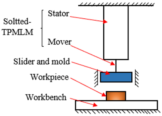
In the conventional low-frequency forming machine shown in Figure 1, 5 there are two parts: the first is the main transmission mechanism as the driving source, which transmits the power generated by the main motor to the mold to provide the forming force; the second is the auxiliary mechanism as the vibration source, which transmits the power generated by the auxiliary motor to the workpiece or the mold to generate vibration force. Obviously, a rotary-linear conversion mechanism must be used, which will make the transmission chain long (the structure is complex and bloated) and affect the forming process and product quality.6,7

A conventional low-frequency vibration forming machine.
As linear motors have developed rapidly in recent years, it has been possible to use them as the driving source for linear motion, simplifying the transmission chain, saving energy, and reducing maintenance. Importantly, it may improve the forming process and product quality. Bai and Yang 8 reviewed that linear motor-driven forming machine is a future development trend. Osakada et al. 9 and Halicioglu et al. 10 summarized the development and application of direct-drive machinery in metal forming and overviewed that direct-drive machinery has the characteristics of simple structure, strong controllability, and high forming quality. Therefore, the use of linear motors to promote the development of low-frequency vibration forming machines is of great significance.
As the driving source of the low-frequency vibration machine, the thrust of linear motors directly provides the forming force and does not require a motion conversion mechanism. Therefore, the linear motor must have sufficient thrust to complete metal forming.11,12 As shown in Figure 2, slotted-tubular permanent magnet synchronous linear motor (slotted-TPMLM), one of the permanent magnet synchronous linear motors, has attracted special attention for its excellent thrust and tubular structure. Therefore, Figure 3 shows a low-frequency vibration forming machine using a slotted-TPMLM as the driving source. Its transmission structure is greatly simplified compared with the machine in Figure 1.

Slotted-tubular permanent magnet synchronous linear motor: (a) 3D diagram and (b) 2D semi-section diagram.

Low-frequency vibration forming machine using a slotted-TPMLM as the driving source.
Although slotted-TPMLM has an excellent thrust, its thrust fluctuation is correspondingly large. The thrust fluctuation is affected by the superposition of end force, cogging force, and fluctuation of electromagnetic thrust force. Importantly, the thrust fluctuation cannot be eliminated. The reason is as follows: the first is that the end force is caused by the end-breaking phenomena, that is, the interaction between the permanent magnet and the end; the second is that the cogging force is generated by the interaction between the PMs and the slots. Both the end force and cogging force are related to structure. In addition, the fluctuation of electromagnetic thrust force is greatly influenced by the excitation current.
In the research on thrust fluctuation of slotted-TPMLM, the optimization or suppression of thrust fluctuation has always been a focus. Many scholars have put forward optimization and improvement measures according to thrust fluctuation’s influencing factors and characteristics. It can be divided into two ways: the first is structure and the second is electric drive.
Structure
Structural optimization affects the end force and cogging force. For example, Hor et al. 13 and Zhu et al.14,15 conducted Fourier analysis and energy method on slotted and slot-less TPMLM to obtain equations about end force and cogging force, and proposed methods to reduce thrust fluctuation by improving the motor structure. Wu et al., 16 Kou et al., 17 Li et al., 18 Tan et al., 19 and Huang et al. 20 optimized the slotted and slot-less TPMLM to improve thrust density and reduce thrust fluctuation by optimizing the length, magnetization direction, slot size, and other relevant parameters. Hou et al. 21 studied the effect of different slot sizes on the cogging force to suppress thrust fluctuation. Bianchi et al. 22 put forward a design criterion of linear motors. Wang et al. 23 optimized a conventional axial magnetized PM motor and studied its thrust density and back electromotive force, and then put forward a design optimization criterion and topology structure. Ashabani et al. 24 optimized TPMLM through a multi-objective design of four variables (magnet width, number of slots per pole-piece, slot width, slot depth). Pan et al. 25 established an analytical model of magnetic resistance generated by the side-effect and put forward the principle and method of optimizing the primary length to reduce the sum of cogging and end forces. Zhao and zhang 26 analyzed the influence of different parameters on thrust density. van Zyl and Landy 27 optimized the length of the permanent magnet. Wang et al. 28 used a virtue work method to study the cogging force and carried out multi-objective optimization. Gieras 29 discussed the cogging torque in PM brushless motors, and derived the cogging torque equations through magnetic field energy. Further, Gieras 30 gave the main dimension calculation procedures and design guidelines of the motor.
Electric drive
The electric drive affects the fluctuation of electromagnetic thrust force. For instance, Tomczuk et al. 31 carried out the field analysis for different values of exciting current and for variable mover position to calculate magnetic field distribution and integral parameters for the slotted-linear motor. Fu et al. 32 proposed a compensation strategy based on the inverse model iterative learning control and robust disturbance observer to suppress the influence of thrust fluctuation. Wang et al. 33 reviewed the residual vibration characteristics and suppression, and summarized the control compensation to suppress the fluctuation. Tan et al. 34 studied the inductance unbalance and the thrust fluctuation characteristics for the slot-less TPMLM, and built voltage and thrust models according to the laws of the inductance unbalance. Further, Li proposed an optimization scheme. Zhu and Cho 35 focused on thrust fluctuation ripples reduction based on the predictive control algorithm. It used compensation by injecting the instantaneous current to counteract the thrust fluctuation.
The existing researches and optimization methods all strive to minimize thrust fluctuation. However, the thrust fluctuation of slotted-TPMLM is rarely reported as a useful force. In addition, the frequency of the thrust fluctuation caused by the structure (end force and cogging force) is related to the speed of the motor mover and the period of the end force and the cogging force, that is, the frequency is the ratio of the speed to period. Since the speed is controllable, this frequency can achieve a lower level. Therefore, Figure 4 displays a novel mechatronics idea of low-frequency vibration forming machine. The slotted-TPMLM is the core component, which is acted as both the driving source and the vibration source. Here, the thrust fluctuation of slotted-TPMLM is the vibration force; the average thrust of slotted-TPMLM is the forming force.
Mechatronic idea of low-frequency vibration forming machines.
The key is the thrust fluctuation of slotted-TPMLM. The thrust fluctuation can be designed and obtained from the electric drive and structure. But, if the required thrust fluctuation is only obtained by the electric drive, it may affect the average thrust and the operation of the motor. Therefore, this research pays more attention to the thrust fluctuation caused by the structure, that is, end force and cogging force. It will provide a basic thrust fluctuation unaffected by the excitation current.
In this paper, the thrust fluctuation of slotted-TPMLM affected by the structure is studied, especially the effect of stator adjustment length on end force and the influence of pole-slot combination on cogging force. The article is organized as follows: Section 1 introduces the mechatronic idea of low-frequency vibration forming machine, points out that the thrust fluctuation of slotted-TPMLM can be used as the vibration force, and proposes that the thrust fluctuation caused by the structure can be designed. Section 2 summarizes the technical characteristics of low-frequency vibration forming, puts forward the technical requirements of slotted-TPMLM, gives the design process of the slotted-TPMLM, and briefly describes the electromagnetic thrust force. Section 3 focuses on the thrust fluctuation caused by the structure, namely end force and cogging force. Section 4 presents the prototype of slotted-TPMLM and shows two experimental platforms to test the motor. Section 5 discusses the experimental results. Section 6 summarizes the conclusions.
Slotted-TPMLM
In this section, the technical requirements of slotted-TPMLM are firstly given. Then, the design process of the slotted-TPMLM is presented. Finally, the electromagnetic thrust force is briefly described.
Characteristics and technical requirements
The low-frequency vibration forming experiments of Q235 and 45# (the Grade of carbon steel) show that the forming force of 10–14 kN with the vibration force of 0–3 kN can improve the forming process and product quality.3,4 In the experiments, the frequency of the vibration force was lower than 300 Hz. In fact, a frequency less than 150 Hz is sufficient.
In Figure 4, the slotted-TPMLM is the main component. Its average thrust is forming force and its thrust fluctuation is vibration force. To facilitate tests and reduce the difficulty of manufacture, a small slotted-TPMLM will be designed and developed. Its maximum average thrust is 3.5 kN so the motor structure can be reduced. At the same time, it can be known from the experiments that the ratio of vibration force to forming force is about 15%–45%. By analogy, the thrust fluctuation should also be in this ratio.
Equation (1) shows the expression of the thrust fluctuation ratio η of slotted-TPMLM. However, once the structure is determined, the thrust fluctuation caused by end force and cogging force is relatively stable and can be regarded as the basic thrust fluctuation. Therefore, in the design process, the cogging force and end force should be selected carefully.
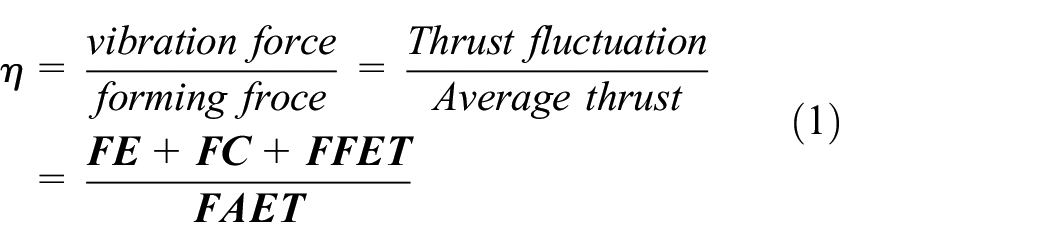
Where,
Design process of the slotted-TPMLM
Figure 5 shows the design process of the slotted-TPMLM. The thrust of slotted-TPMLM can be divided into the average thrust provided by electromagnetic thrust force and the thrust fluctuation. The thrust fluctuation is affected by end force, cogging force, and fluctuation of electromagnetic thrust force.

Design process of the slotted-TPMLM.
During the design of slotted-TPMLM, it is first necessary to make the average thrust of the electromagnetic thrust force meet the requirements.29,36 Thereby, the main electrical parameters and structural parameters of the motor are determined. For the fluctuations caused by electromagnetic thrust, an estimate is made (e.g. the fluctuation of electromagnetic thrust is more than 10% of the average electromagnetic thrust). Then, the thrust fluctuation can be designed through structural optimization.
In order to obtain a desired basic thrust fluctuation caused by the structure, it can be through adding auxiliary slots, optimizing the slots, changing the end structure, and so on.18,23,27,28 However, these affect the main electrical and structural parameters previously determined. Moreover, it may cause a reduction in the average thrust.
In this paper, on the premise of not affecting the average thrust, the desired basic thrust fluctuation can be obtained by changing the stator adjustment length and the pole-slot combination. As shown in the red box in Figure 5, this is an auxiliary path in the design process and does not affect the change of the main technical parameters of the motor.
Electromagnetic thrust force
The coils are fed with a three-phase symmetrical sinusoidal current to generate a traveling wave magnetic field, so the mover can be reciprocated with a certain electromagnetic thrust force. Notably, the electromagnetic thrust force is an important parameter that achieves normal operation and provides the forming force. Here, the power and electromagnetic thrust force of the motor are as follows 36 :


Where, Pe is electromagnetic power, kw; E0 is the back electromotive force (back-EMF), V; Im is the excitation current, A; ψ is power factor angle; v1 is the mover’s speed, m/s; τ is the pole pitch, m;
End force and cogging force
In this section, the thrust fluctuations caused by the structure are discussed in detail through Fourier analysis, especially the effect of stator adjustment length on end force and the influence of pole-slot combination on cogging force.
End force
The end force has two components F+ and F−, each of which changes periodically with pole pitch τ and can be Fourier analyzed.13–15,29 The output of the end force is related to the relative position of the mover.
Figure 6 shows the analytical model of the end force, which is a slotless-TPMLM. In this model, only the force fluctuations due to end-breaking phenomena are considered. Here, the stator iron core length (L) can be expressed as L = kτ + αph (Here, k is a positive integer, αph represents stator adjustment length).

Analytical model of the end force.
The following assumptions for F+ and F− analysis can be made: the first is that the stator is of infinite length; the second is that the mover is infinitely long on one side. As a result, each force component is simplified as shown in Figure 7. If the stator iron core length (L) is long enough (in fact, when the k is more than 3, the length is enough), the force at one end can be considered irrespective with the other end.13–15,29 Therefore, the total end force can be obtained by summing F+ and F−.
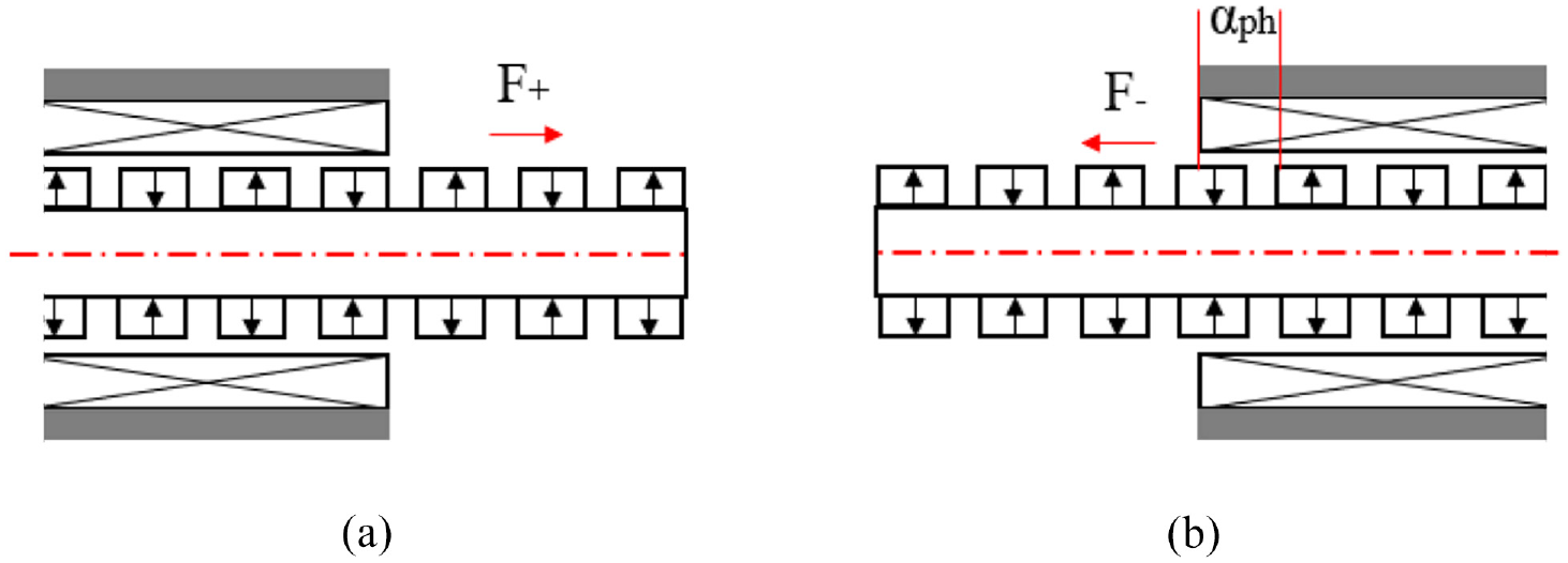
Analytical model of two components of the end force: (a) right end and (b) left end.
The end force on the right is expanded in Fourier form as shown in equation (4).

The end force on the left of the relative position (kτ + αph) can be given by the mirror image.

Consequently, the total end force can be obtained by the superposition principle. After trigonometric simplification, the expression of the total end force is shown as follows:

Here, the amplitude Fm can be expressed as follows:

Where, F0 represents the basic end force, m represents mth order harmonic, z is the relative position to a reference position, Fsm represents the mth order sine term, and Fcm represents the mth order cosine term.
It can be seen from equation (7) that different αph will have different effects on the amplitude Fm in the end force. Therefore, the effect of stator iron core length (L) (especially, the stator adjustment length (αph)) on end force is discussed. When the main parameters of the motor are designed (especially, pole pitch τ is determined), the required total end force can be designed by selecting the appropriate length αph. For instance, as shown in Figure 8, different lengths αph affect the magnitude and waveform of the end force, which can be used to obtain the desired end force. Correspondingly, the desired end force can be obtained by selecting an appropriate stator iron core length (kτ + αph), pole pitch τ, and especially αph.
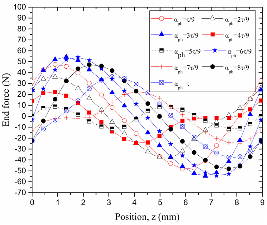
Effect of different αph on the magnitude and waveform of end force.
Cogging force
The cogging force changes periodically with slot pitch τs, but it also can be expressed by the pole pitch τ. It also can be Fourier analyzed, and the output of cogging force is also related to the relative position of the mover.
The cogging force generated by only one slot is firstly analyzed. Figure 9 shows the calculation model. Here, the lengths of the stator and the mover are infinite. In this model, the period of cogging force varies with the pole pitch (τ). When the pole pitch (τ) is defined as an Electric period (τ = 2π), the Fourier analysis of the cogging force generated by one slot is as follows 37 :

Where, x is the relative position to a reference position; n represents the nth order harmonics; Fn and θn are the amplitude and angle of the nth order harmonics, respectively.

Cogging force calculation model with a single slot.
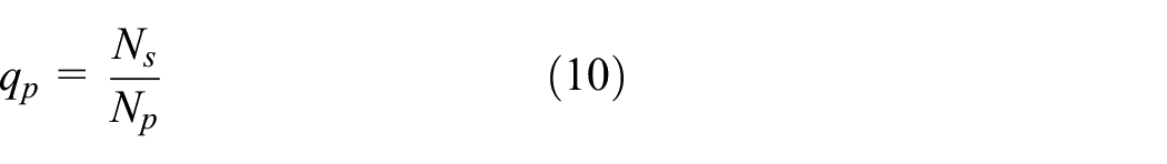
Figure 10 shows the analytical model of the cogging force with multiple slots. Here, only the force fluctuation caused by the stator slots is considered; the effect of end breaking is not included. In the model, Ns slots and Np poles are evenly distributed (both Ns and Np are integers); the pole pitch is τ; both tooth pitch and slot pitch are τs. Define qp to represent the tooth pitch τs within a pole pitch τ.


Cogging force calculation model with the multiple slots: (a) calculation model with the multiple slots and (b) equivalent model.
In Figure 10(a), it can be learned that
Since the slotted-TPMLM is obtained by structural transformation from a PMSM. Therefore, the slotted-TPMLM has a certain analogy with the PMSM. The equivalent model of Figure 10(b) can be obtained by transforming the model of Figure 10(a).
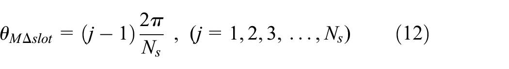
In Figure 10(a) and (b), the Mechanical position difference

Define
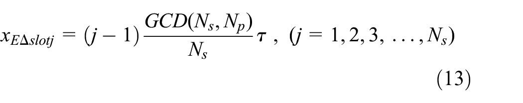
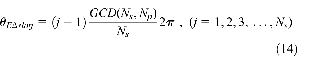
If the interaction between slots is ignored, the expression for the cogging force of each slot is similar to equation (8) with a different relative position. The expression for the cogging force of the jth slot is as follow (
Further, the total cogging force can be obtained through the superposition principle.

After trigonometric simplification, equation (16) can be expressed as equation (17).

In equation (17), it is easy to prove the following formula.

Where, n is an arbitrary integer.
Further, the expression of cogging force (equation (17)) can be simplified.
In equation (19), it is also easy to prove the following formula.

Where, k is an integer.
If n is an integer multiple k of

Redefine, use the letter n for k, and

Equation (22) shows that the total cogging force only contains
If
Equation (22) implies that the larger
As shown in Table 1, for example,
N cf value under different pole—slot combinations.

Prototype and experiment
In this section, the prototype of slotted-TPMLM is presented. In addition, two experimental platforms are built to test the thrust fluctuation of the designed-TPMLM.
Prototype
A small slotted-TPMLM is designed and developed. Figure 11 shows the structure diagram and prototype of the designed-TPMLM. It adopts a concentrated winding structure with 20 poles and 24 slots. Here, qp = 1.2, αph = τ/9, ncf = 6, the detail electromagnetic parameters are shown in Table 2.
The structure diagram and prototype of the designed slotted-TPMLM with 20 poles and 24 slots: (a) structure diagram and (b) prototype.
Electromagnetic parameter of designed slotted-TPMLM.
Experiments
Trailing experiment
Since the end force and cogging force are only related to the structure and are a function of the relative position of the mover, the three-phase coils of slotted-TPMLM is short-circuited to fully reach the electromagnetic conditions. Figure 12 shows an experimental platform for the trailing experiment. Here, only the end force and cogging force are included in this experiment, and the electromagnetic thrust force is not considered.

Experimental platform for trailing experiment: (a) experiment sketch and (b) experimental platform.
The platform is composed of the slotted-TPMLM, a rack and pinion mechanism, a trailing motor, a workbench and sensors. The mover of slotted-TPMLM is connected to the gear rack through a force sensor. The function of the rack and pinion mechanism is to convert rotary motion of the trailing motor into a linear motion. Therefore, it can pull the mover of slotted-TPMLM to complete linear motion. The trailing motor is a permanent magnet synchronous traction motor (Xizi Elevator Co., Ltd.). It has the characteristics of low speed and high torque and has excellent speed regulation ability.
Load experiment
Figure 13 shows an experimental platform for the load experiment. In this experiment, the three-phase sinusoidal excitation current is applied. Therefore, the thrust fluctuation consists of cogging force, end force, and fluctuation of electromagnetic thrust force.
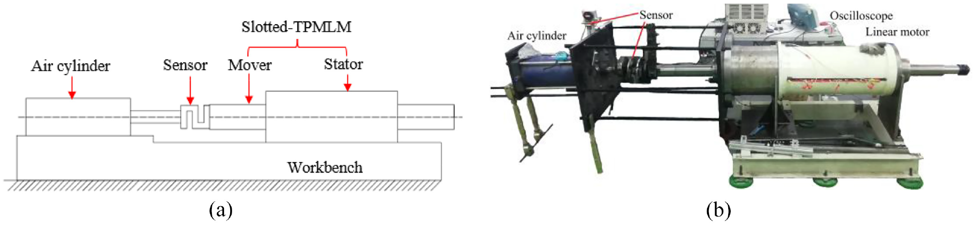
Experimental platform for load experiment: (a) experiment sketch and (b) experimental platform.
The experimental platform includes five parts: air cylinder, slotted-TPMLM, force sensor, displacement sensor, and experimental base. The air cylinder provides a constant load. The mover of slotted-TPMLM is connected to the air cylinder through a force sensor, and the mover of the motor will move under the action of electricity to overcome the constant load provided by the cylinder. Here, the force sensor measures the thrust fluctuation. Table 3 shows the main technical parameters of the air cylinder. The load of the air cylinder is calculated using the pressure formula (equation (23)).

Where, ηF is the air output efficiency; PF is the pressure; S is the piston area.
Main technical parameters of cylinder.

Results and discussion
In this section, the results obtained from the experiments are discussed. The feasibility of the mechatronics idea of low-frequency vibration forming machine is discussed.
Resultant force of end force and cogging force
Ideally, when the slotted-TPMLM is manufactured with sufficient precision and the slotted-TPMLM is placed vertically (the angle between its gravity and the normal force is 90°), the normal forces cancel each other out due to the tubular structure. In this ideal condition, there is almost no mechanical friction when the mover moves. However, it is difficult to achieve. Therefore, friction is included in the test results.
Figure 14 shows the test results obtained in the trailing experiment. Figure 14(a) is a curve of the thrust fluctuation in the trailing experiment. It can be divided into three segments: front, middle, and back segments. The front and back segments in Figure 14(a) are the force obtained when the motion stops; the middle segment shows the force obtained during movement, and the velocity is approximately 100 mm/s. In addition, Figure 14(b) is a local enlarged figure of the middle segment of thrust fluctuation; Figure 15 is the Fourier spectrum analysis of Figure 14(b).
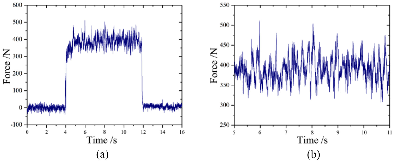
The thrust fluctuation of the slotted-TPMLM when the velocity of the mover is approximately 100 mm/s: (a) the thrust fluctuation throughout the whole process and (b) the enlarged figure of the thrust fluctuation (middle segment) during motion).

The Fourier spectrum analysis of the thrust fluctuation, where the velocity of the mover is approximately 100 mm/s.
When the mover does not move (relative position does not change), it just has a trend of movement. However, the static friction force restrains the movement tendency of the mover. As shown in the front and back segments of Figure 14(a), the force fluctuation is the combination of the static friction force and the resultant force of end force and cogging force. Here, it is maintained near 0 N; the fluctuation is about 60 N (±30 N). In a word, such comprehensive influence makes the mover of slotted-TPMLM have a movement tendency of reciprocating motion, but does not move in a relative position. It just shows a thrust fluctuation phenomenon.
When the mover moves, there is relative motion between the stator and the mover of the slotted-TPMLM. Therefore, there is a constant sliding friction force (equation (24)) to hinder the motion. As shown in the middle segment (Figure 14(b)) in Figure 14(a), the force fluctuation is the combination of the sliding friction force and the resultant force of end force and cogging force. In Figure 14(b), the force is between 330 and 450 N and the fluctuation is about 120 N. Consequently, the sliding friction force is 390 N and the direction is always opposite to the movement direction of the mover.

Where, μ is the kinetic friction factor, FN is the normal force between the mover and the stator. Here, the normal force is mainly gravity.
The end force changes with the pole pitch τ and its Fourier form can be expressed with sine terms (equation (6)); although the cogging force changes with the slot pitch τs, it can express by the pole pitch τ with sine terms (equation (21)). Therefore, the resultant force of end force and cogging force can also be expressed by the pole pitch τ with sine terms. It is a periodic function with the period of pole pitch τ. In Figure 14(b), the force fluctuation is approximately sinusoidal. Figure 15 shows the Fourier spectrum analysis of Figure 14(b). The results show that there are mainly two frequencies, one is the fundamental frequency and the other is about 4.8 Hz. Among them, the fundamental frequency represents the sliding friction force; the frequency of 4.8 Hz denotes that the fluctuation is related to the end force and the end force, which is caused by the relative position change when the mover moves.
In the test, the mover is conducted at approximately 100 mm/s; the pole pitch τ of the motor is 19.96 mm. Consequently, according to equation (25), the frequency of the resultant force of end force and cogging force is calculated theoretically to be about 5.01 Hz. However, in Figure 15, the experimental results show that the frequency is about 4.80 Hz. There is a certain difference between the experimental result and the theoretical calculation, and this difference may be due to errors in the manufacturing and assembly process. Most importantly, both 4.80 and 5.01 Hz are the low-frequency, within the frequency requirements of low-frequency vibration forming machine.

Where, f represents the frequency of the fluctuation of end force and cogging force, Hz; v is the velocity of the mover, mm/s; τ is the pole pitch, mm.
Electromagnetic thrust force
In the load experiment, the slotted-TPMLM is driven by the three-phase excitation current to overcome a constant load. Here, the thrust fluctuation is affected by end force and cogging force, and fluctuation of electromagnetic thrust force. Similarly, the test results also contain friction. In the previous section, the resultant force of end force and cogging force is studied, which is only related to structure. In this section, the fluctuation of electromagnetic thrust force is investigated.
Figure 16 shows the thrust fluctuation of slotted-TPMLM under different excitation currents. Figure 16(a) expresses that when the excitation current is 3 A, the average thrust is 1750 N and the fluctuation is 210 N (excluding outliers); Figure 16(b) reveals that when the excitation current is 5.6 A, the average thrust is about 2600 N and the fluctuation is 400 N (excluding outliers). In previous section, the fluctuation caused by the end force and cogging force is 120 N. Therefore, the fluctuation of electromagnetic thrust force is 90 N at 3 A, and 280 N at 5.6 A, respectively.

The thrust fluctuation of the motor under two different excitation currents: (a) the thrust fluctuation at 3.0 A excitation current and (b) the thrust fluctuation at 5.6 A excitation current.
As shown in Figure 17, it is analysis results of the thrust fluctuation under different excitation currents. Figure 17(a) shows a relationship curve between thrust fluctuation and excitation current; Figure 17(b) expresses a relationship curve between average thrust and excitation current; Figure 17(c) reveals a relationship curve between the thrust fluctuation ratio and the excitation current.

The analysis of thrust fluctuation under different excitation currents: (a) a relationship curve between thrust fluctuation and excitation current, (b) a relationship curve between average thrust and excitation current, and (c) a relationship curve between the thrust fluctuation ratio and the excitation current.
In Figure 17(b), the average thrust increases proportionately with the increase of the excitation current. Notably, when the excitation current increases to 5 A, the growth rate of the average thrust will gradually decrease. In Figure 17(c), when the excitation current exceeds 2 A, the thrust fluctuation ratio remains around 16.5%.
In Figure 17(a), when the excitation current is small (less than 2 A), the thrust fluctuation is small (less than 200 N, about 175 N). Here, the thrust fluctuation caused by the end force and cogging force plays a dominant role. At this time, the thrust fluctuation ratio is greater than 20% shown in Figure 17(c). However, when the excitation current is greater than 9 A, the thrust fluctuation gradually becomes stable at about 550 N. At this time, the fluctuation of electromagnetic thrust force is about 430 N, which plays a leading role. At this time, the thrust fluctuation ratio is relatively stable at about 15%–17% shown in Figure 17(c). In addition, the fluctuation reaches a stable state due to the saturation of the magnetic field within the pole pitch caused by the excitation current.
When the excitation current is greater than 2 A and less than 7 A, the thrust fluctuation increases in a certain linear proportion. Here, the thrust fluctuation caused by the end force and cogging force is still about 120 N. Apparently, when the excitation current is 5 A, the thrust fluctuation is about 350 N, of which the fluctuation of electromagnetic thrust force is about 230 N; when the excitation current is 7 A, the thrust fluctuation is about 500 N, of which the fluctuation of electromagnetic thrust force is about 380 N; when the excitation current is 9 A, the thrust fluctuation is about 550 N, of which the fluctuation of electromagnetic thrust force is about 430 N. Consequently, as shown in Figure 17(c), when the excitation current is between 2 and 9 A, the thrust fluctuation ratio is about 16.5%.
Further, the frequency of the thrust fluctuation is in the low-frequency range. Here, the frequency of fluctuation caused by the end force and cogging force is about 4.8–5 Hz at 100 mm/s (48–50 Hz at 1000 mm/s). Due to the action of the traveling wave magnetic field and the characteristics of the synchronous motor, the magnetic field of the electric excitation is consistent with the running speed of the motor mover. Therefore, the frequency of the fluctuation of electromagnetic thrust force is basically consistent with the frequency of the end force and cogging force during the mover moving. Accordingly, the thrust fluctuation is in a reasonable range, which meets the requirements of low-frequency vibration forming.
Feasibility of the mechatronics idea
As shown in Figure 4, it is a mechatronics idea of low-frequency vibration forming machine. Here, the slotted-TPMLM is acted as both driving source and vibration source.
The thrust fluctuations of slotted-TPMLM are two types: the first is that the end force and cogging force are only related to structure; the second is that the fluctuation of electromagnetic thrust force is related to the excitation current. In this article, the focus is on the end force and cogging force. Accordingly, design end force and cogging force by improving the stator adjustment length αph and selecting the pole-slot combination. It provides the basic thrust fluctuation. The tests show that the thrust fluctuation ratio of the designed slotted-TPMLM is greater than 15%. Usually, the frequency of this thrust fluctuation is not more than 50 Hz.
In general, the structure of slotted-TPMLM can be designed and manufactured for specific occasions through changing the thrust fluctuation caused by the end force and cogging force, which can be regarded as basic thrust fluctuation. However, once the structure is determined, the end force and cogging force are relatively constant. Consequently, after determining the structure of slotted-TPMLM, the electromagnetic thrust force is regulated by the excitation current, which can not only increase the average thrust, but also increase the fluctuation of electromagnetic thrust force. This will help keep the thrust fluctuation ratio within a certain range.
Conclusion
In this paper, a novel mechatronic idea of low-frequency vibration forming machine is presented. The design process of slotted-TPMLM is described. The thrust fluctuation of slotted-TPMLM caused by end force and cogging force is discussed in detail. Accordingly, the structure of slotted-TPMLM can be modified to provide a basic thrust fluctuation as a useful force. Some useful conclusions are as follows:
The end force and cogging force are only related to the structure. The desired end force is obtained by improving a suitable stator adjust length αph; the desired cogging force is obtained by optimizing the pole-slot combination Np and Ns. It can be modified as a basic thrust fluctuation. The frequency fluctuation caused by end force and cogging force is the ratio of the velocity of mover to the pole pitch. The results show that the frequency is in the low-frequency range (4.8 Hz at 100 mm/s; 48 Hz at 1000 mm/s).
The fluctuation of electromagnetic thrust force is related to the excitation current. The experiment shows that the thrust fluctuation of electromagnetic thrust force gradually dominates with the increase of the excitation current. Once the structure of the slotted-TPMLM is determined, the end force and cogging force are relatively constant, and the thrust fluctuation can be regulated by the fluctuation of electromagnetic thrust force to maintain a large thrust fluctuation ratio. Therefore, the next work is to develop the influence of the fluctuation of electromagnetic force affected by the electric drive.
Using the thrust fluctuation of a linear motor as a useful force and applying it in low-frequency vibration forming machine is feasible. Compared with the traditional machine, the mechatronics idea of low-frequency vibration forming machine greatly simplifies the overall structure. The resultant force of the end force and cogging force provides a basic thrust fluctuation. The fluctuation of electromagnetic thrust force changes with the increase of average electromagnetic thrust force, which will keep the thrust fluctuation ratio in a relatively stable range for the low-frequency vibration forming machine. The research will contribute to the fields of linear motors and metal forming machines.
Footnotes
Handling Editor: Chenhui Liang
Declaration of conflicting interests
The author(s) declared no potential conflicts of interest with respect to the research, authorship, and/or publication of this article.
Funding
The author(s) disclosed receipt of the following financial support for the research, authorship, and/or publication of this article: The present work is financially supported by the National Natural Science Foundation of China (U1937203), State Key Laboratory for Mechanical Behavior of Materials (1991DA105206), Huxiang High-Level Talent Gathering Project of Hunan Province (Grant No. 2021RC5001), and the China Scholarship Council (202106280193).