
Abstract
The use of mechatronic integrated equipment, such as servo feed drive systems, has become increasingly important in high-end manufacturing, aerospace, and semiconductor industries. However, while advancements in modeling and analysis have improved deterministic feed systems, there is a lack of research into uncertain motion accuracy due to random factors in actual working conditions. This paper aims to address this issue by analyzing the uncertainty of motion accuracy in single-axis feed drive systems. Random factors already impact both positioning accuracy and repeatability, while dynamic errors are reflected in the mean and variance of following errors. The study also considers the impact of disturbance uncertainty, parameter uncertainty, and model uncertainty on motion accuracy. To investigate the impact of these sources of uncertainty on a six-degree-of-freedom linear motor feed system, a simulation example using the Monte Carlo simulation algorithm was utilized. The analysis revealed that uncertainty indeed has an impact on motion accuracy. This research will help identify and improve random errors in servo feed systems, ultimately leading to the development of strategies for reducing motion accuracy uncertainty and enhancing the accuracy and reliability of feed systems in high-end manufacturing, aerospace, and semiconductor industries.
Introduction
High-end CNC machine tools are “industrial mother machines” and play a significant role in the high-end manufacturing industry, influencing industries such as aerospace, semiconductor, marine, and high-speed railway.1–3 The accuracy of machine tools is a crucial indicator of their technical level, with the accuracy of the CNC machine tool feed drive system being a key factor that determines the performance and accuracy of machine tools. The machine tool feed drive system is a typical mechatronic integrated system, and its motion control is a typical control problem that occupies a significant position in both academic and industrial fields, receiving extensive attention and achieving fruitful results. Currently, the motion control strategy of the feed system based on the three-loop control PID method has been widely used in industry and some advanced control algorithms have been initially promoted.4,5 In academia, there has been extensive progress in the dynamical system modeling,6–8 system identification,9–11 motion accuracy source analysis for machine tool feed system and traceability,12,13 and motion accuracy improvement.14–16 However, the current mainstream research direction treats the machine tool feed system as a linear time-invariant system (LTI) for analysis. Some works have also considered the time-varying and parameter-varying characteristics of the feed system.17–19 In particular, significant progress has been made in dealing with parameter perturbations and external disturbances of motor drive systems based on fuzzy methods,20–23 and in recent years, more scholars have further combined this method with neural networks, and the control improvement effect is remarkable.24,25 Furthermore, the influence of nonlinear factors of the feed system, such as clearance 26 and input saturation, 27 on the motion accuracy has also been analyzed and improved. In summary, the machine tool feed drive system is a crucial component of high-end CNC machine tools, and its accuracy is essential to determine the performance and accuracy of machine tools. While current research has achieved fruitful results in the motion control of the feed system, the current mainstream research direction treats the system as an LTI for analysis, and some works have also considered the time-varying and parameter-varying characteristics of the feed system. However, the influence of nonlinear factors of the feed system, such as clearance and input saturation, on the motion accuracy requires further investigation. Therefore, future research should focus on developing new control algorithms and exploring the influence of nonlinear factors to improve the accuracy and performance of high-end CNC machine tools.
In the present study, we aim to shed light on the issue of uncertainties in machine tool feed systems, which are currently regarded as deterministic systems by both industry and academia, with a view to enhancing their analysis and optimization. Despite this, the physical system itself is characterized by stochastic laws and statistical features that exhibit uncertainty characteristics. Such uncertainties pose significant challenges in various engineering problems and may stem from the complexity of the problem, limitations in our ability to understand the underlying objective, errors in machining structural dimensions, measurement errors, and assumptions made during the design process. Ignoring the influence of multiple random factors during the machining process when modeling, analyzing, and controlling the machine tool feed system can lead to significant deviations between the analytical model output and the actual system output, as well as the dispersion of the output. Therefore, it has become imperative to design and optimize systems that take uncertainties into account, a topic that has gained significant interest in various fields, including aerospace dynamics, 28 automotive dynamics, 29 and robotics. 30 However, the analysis and optimization of the motion accuracy of machine tool feed systems under uncertainty are still in their nascent stage. 31 Particularly, there is no standard definition or consensus in the academic community concerning the sources and definition of motion accuracy of feed systems under uncertainty.
In this regard, we propose to address this research gap by presenting a definition for motion accuracy uncertainty of machine feed systems and its sources by integrating existing industrial standards and experimental outcomes. Our primary objective is to lay the groundwork for future studies in the field of motion accuracy uncertainty and improve the accuracy of models for machine tool feed systems.
The main contributions of this article can be summarized as follows: (1) a new evaluation index for the motion accuracy uncertainty of the feed system, which comprehensively considers the characteristics of the entire stage of the system operation process, combining ISO international standards and actual conditions, is defined. An evaluation index that comprehensively considers the motion accuracy uncertainty of the feed system under static and dynamic conditions is proposed; (2) a new motion accuracy uncertainty analysis and traceability strategy is presented. Three sources of uncertainty, namely disturbance uncertainty, parameter uncertainty, and model uncertainty, are considered for the actual working conditions of the feed system, and the impact of these three uncertainties on the output response characteristics of the dynamic system is verified based on simulation algorithm.
The remainder of this article is organized as follows: the classification and definition of error uncertainty are presented in the “Machine tool feed system motion accuracy uncertainty definition” section. The specific descriptions and definitions of the three types of uncertainty are provided in the “Analysis of feed system uncertainty factors” section. Finally, in the “ Simulation case analysis” section, the evolution law of the system output characteristics under the influence of different uncertainty factors is analyzed through simulation based on the workbench dynamic model.
Machine tool feed system motion accuracy uncertainty definition
The evaluation of CNC machine tool motion accuracy is critical in engineering applications as it has a direct impact on the final product’s quality and precision. In this regard, the assessment of two key metrics, namely positioning accuracy and positioning repeatability, is commonly employed as a quasi-static measurement and evaluation method. Motion accuracy refers to the level of agreement between the CNC command and the actual displacement of the motion axis, and it is characterized by a multidimensional error sequence that reflects the degree of conformity between the two variables. It’s as shown in equation (1):

The accuracy of CNC machine tool motion is closely tied to factors such as machine motion speed and acceleration. While positioning accuracy and positioning repeatability of axis are well-defined in ISO 230.2-2014 32 for low-speed motion and measured after stabilization, motion accuracy is evaluated more comprehensively and described more extensively. Specifically, motion accuracy assesses the degree of conformity between the actual displacement of the motion axis and the CNC command in a broader range of operating conditions, including high-speed motion and transient states. However, the measurement of motion accuracy is subject to uncertainty, which can be attributed to factors such as machine dynamics, measurement instrumentation, and environmental conditions. To address this issue, this paper defines uncertainty for the two standard definitions of accuracy mentioned above. By providing a more comprehensive and precise understanding of the accuracy of CNC machine tool motion, this work aims to enhance the quality and reliability of manufacturing processes in engineering applications.
Positioning accuracy and positioning repeatability
Presently, there are multiple standards for defining and measuring machine tool feed system errors, with the international standard ISO230-2 (2014) 32 being the most commonly employed and acknowledged. The ISO standard outlines the origin of measurement as a reference point that moves a certain distance from zero to a point that is near the end of the whole movement. The measurements are taken by measuring linear movement in both directions and the number of measurements required is at least five points in the range of 1–2 m for each direction. At least five measurements are required in each direction.
Positioning accuracy refers to the range that is equal to twice the sum of the deviation of the positioning system and estimation of the uncertainty in positioning standard. Positioning repeatability refers to the maximum spread around the target point. This is formally defined in (2):

Where
The definition of the equation (2) reveals that the positioning accuracy and repeatability already contain considerable uncertainty, which is caused by the deviation dispersal of the feed system at the measuring point. The positioning accuracy is determined by the mean value and deviation dispersal of the deviation, whereas the repeatability is determined by deviation dispersal for a single occasion. Thus, both the positioning accuracy and the repeatability display significant levels of uncertainty and can be considered uncertainties in the motion accuracy of the feed drive system.
According to the international standard, the positioning accuracy and positioning repeatability of the X-axis of a five-axis machine tool was tested using the Renishaw XL-80 laser interferometer. The test range was selected as 0–260 mm with a test distance of 20 mm, and 14 points were tested with the positive and negative round trip being run three times. The obtained test results are illustrated in Figure 1, revealing that the calculated values for the positioning accuracy and repeat positioning accuracy were 40.1116

Laser interferometer test points error.
Uncertainty definition of dynamic motion accuracy
In contrast to the positioning accuracy and positioning repeatability that reflect the static characteristics of the feed system, the accuracy of dynamic motion can more fully capture the dynamic characteristics of the acceleration and deceleration stages and the stages of constant speed of the feed system. According to the definition in equation (1), we can further analyze the factors affecting the dynamic motion accuracy of the feed drive system.
Without loss of generality, the feed drive system control framework is shown in Figure 2.

Control framework.
Then there is the position deviation of the feed system over the entire motion trajectory can be defined as shown in the following equation (3):

Where, e is dynamic position deviation; r is motion trajectory; y is feedback displacement; d is equivalent disturbance; G is controlled object transfer function; C is Feedback controller transfer function.
The feedback controller is a PID controller and the mechanical system is a dual inertia system:

Where, Kp is proportional gain; Kd is differential gain; Ki is integral gain; m1,m2 are mechanical system inertias;
Substitute equation (4) into equation (3). In general, the trajectory command energy is concentrated in the low frequency band, and it can be considered that at this time

Analysis of equation (5) reveals that the dynamic position deviation is linearly correlated with the third-order differential, fourth-order differential and higher-order differential of the commanded trajectory, which proves that a significant position deviation occurs during the acceleration and deceleration of the feeding system, and the deviation value is closely related to the commanded trajectory; in the uniform speed section, since the second-order differentials of the commanded trajectory are all 0, the influence of the trajectory on the position deviation is not significant at this point in time. The influence of the trajectory on the position deviation currently is not significant. However, at this time, the influence of external disturbance on the position deviation cannot be ignored, and the influence of disturbance on the motion control of the feeding system must be considered.

The harmonic signal can be converted to a superposition of multidimensional sinusoidal harmonics by Fourier transform, so theoretically, the above equation (6) can be directly obtained by the Laplace transform and the inverse Laplace inverse transform to obtain the exact time domain solution. However, in practical engineering its expression is too complicated and almost has no application value. However, in general, it can be considered that the position deviation under the action of perturbation can also be characterized as the superposition of multidimensional harmonics.
Meanwhile, it can be found that the dynamic deviation is closely related to the parameters of the system such as the intrinsic frequency and inertia, and the mechanical parameters of the feed system can also significantly affect the dynamic deviation of the system.
Most of the control systems, in practice, are digital control systems, which means ZOH exists between the controller and the plant model. Aside from this, time delay is inevitable for a practical control system due to mechanical and electrical factors. Considering the effect of time delay for motion accuracy has been researched by Dai et al., 33 the expression is shown in equation (7). Thus it can be argued that the time delay effect can also be considered as an effect on the system parameters and can be considered as a parameter uncertainty

Where, Gc(0) is dc gain of controller; T is sampling period; τ is time delay.
The existing definition indicates that motion accuracy is the error in motion that occurs during a single operation. The existing definition is unable to fully reflect the statistical distribution patterns of the motion accuracy in the feed drive system. The discussion of motion accuracy uncertainty pertains to a single-axis feed system which conducts multiple repetitive experiments to measure the motion accuracy during each operation. It’s defined as equation (8). The mean and variance of the motion accuracy obtained in multiple trials are then analyzed and utilized to assess the level of motion accuracy uncertainty.

Where
The experimental process ensures that every input system follows an identical command trajectory consisting of the same displacement, velocity, and acceleration commands. Evaluating the motion accuracy uncertainty involves repeating the experiment multiple times, collecting data on the system’s command displacement and feedback displacement, and calculating relevant parameters.
The motion accuracy uncertainty can be regarded as a typical random process within the same set of all possible samples of motion accuracy obtained through random experimentation, as defined above. The uncertainty of motion accuracy during actual operation was analyzed using a specific type of linear motor feed drive system as an example. The experiment set the feed drive system’s displacement at 100 mm and the speed at 16 mm/s for each trial. The experiment was conducted 20 times to collect the data on the following error during each trial. Figure 3 shows the feed system’s displacement and speed commands, as well as the error waterfall diagram for 20 measurements and acquisitions of the system.

Experimental data: (a) feed system displacement and velocity and (b) waterfall diagram of following error.
Analysis of the measured experimental data indicates that the motion accuracy exhibits obvious uncertainty after repeated operation under the same input command, just as show in Figure 4. There was noticeable dispersion between the system’s motion accuracy at different moments, demonstrating that the motion accuracy’s uncertainty significantly affects the system’s operational accuracy consistency. Therefore, it is crucial to trace and analyze the causes underlying the system’s motion accuracy uncertainty.

Following error uncertainty: (a) mean of following error and (b)variance of following error.
It is noteworthy that the mean and variance of the motion accuracy proposed in equation (3) are typical time series, which are difficult to quantify by specific values. Therefore, this paper proposes a quadratic form based on the above sequence as an evaluation index quantity to quantitatively analyze the uncertainty of the feed system motion accuracy, as uncertainty mean indicators

Analysis of feed system uncertainty factors
The mechatronic integrated system, specifically the CNC machine feed system, presents three primary types of uncertainties: disturbance, parameter, and model uncertainties. These uncertainties arise from various sources and have distinct effects.
Disturbance uncertainty
The machine tool machining process is influenced by several factors, including material properties, tool properties, and tool attitude. It can accurately predict the size and direction of the nominal force for five-axis cutting. However, the actual cutting force cannot be accurately predicted due to some uncertainty. Additionally, the machining process of the machine tool experiences external disturbances such as motor thrust harmonics, spindle system vibration, and shop machining vibration. The formation mechanism, spectral characteristics, and mode of action for these disturbances are different, leading to some uncertainty.
Disturbances in the single-axis feed system during operation mainly originate from three primary sources: thrust harmonics due to the motor and drive system’s own structure, non-linearity, and other factors; frictional and cutting forces during machine processing; and external vibration, among other factors.
During operation of the feed system, the motor’s output thrust generated by characteristics of the motor body structure, drive system nonlinearity, and other factors produces various types of harmonic thrusts, such as those due to drive dead time, cogging structures, and motor circuit nonlinearity (e.g. inductance asymmetry), as well as ripple forces resulting from the arrangement of permanent magnets. These harmonic thrusts occur at multiple frequencies and from several sources. In addition to the nominal force, linear motor feed systems also exhibit end forces due to the table’s structural characteristics.
During motion, the position, speed, and acceleration of the feed system change, and the system load may also fluctuate. Each harmonic component of the motor’s output thrust is not constant and varies with different motion parameters. Ripple thrust is proportional to the amplitude of each harmonic component of the output current of the servo circuit and to the speed and position of the feed motion. In contrast, cogging and end forces result from motor structure factors and depend only on the speed and position of the feed system. Finally, the nonlinearity of the motor circuit produces harmonic forces that are related to the nominal current of the servo armature output and depend on the speed and position of the feed motion. Overall, the motor’s output thrust during feed system operation can be explained as equation (10).

Where,
There has been considerable research on the modeling and evolution of each sub-harmonic disturbance in the servo motor operation process,34,35 and explicit expressions have been developed. For example, the linear motor cogging force can be expressed as equation (11) 36 :

Where
Estimating many electromagnetic parameters in these expressions accurately is challenging, and some of these parameters are not measurable. For example, the harmonic thrust generated by the motor, which is the sum of an infinite number of harmonics, must be truncated due to operational constraints when performing actual calculations, leading to new errors. Additionally, the cogging and end forces are not related to the motor servo current, whereas the thrust force (like the ripple and dead-zone harmonic thrust) is directly proportional to the motor servo current. The magnitude of the thrust force is influenced by the load of the motor, running speed, acceleration, and other motion parameters, making these parameters difficult to estimate accurately. As a result, the thrust harmonics resulting from the motor body and drive system nonlinearity during feed system operation are challenging to estimate precisely and can cause random position deviations during point-to-point motion of the feed system.
Friction is a critical factor in determining the position deviation of a feed system. Nonetheless, presently there is no comprehensive friction model that provides a unified framework and describes the changes in frictional force during the motion of the feed system in static, dynamic, and transient states. Friction models can be categorized into two main groups based on whether the model includes differential Equations to describe dynamic characteristics- static friction models and dynamic friction models.
Static friction models such as the Coulomb, static friction + Coulomb + viscous friction, Stribeck friction, and Kamopp friction models37–39 share a common characteristic of zero-velocity point discontinuity of velocity and steady-state friction force. Furthermore, frictional force can take an infinite number of values at zero-velocity point. Nevertheless, these models cannot capture the pre-slip displacement, static friction force variation, friction hysteresis and other nonlinear dynamic friction characteristics. Dynamic friction models including the Dahl, LuGre, Leuven, and generalized Maxwell-slip models, can accommodate and explain the dynamic characteristics of friction. The LuGre model defines friction force as a function of relative velocity (sliding stage) and displacement (pre-slip stage). It is the first model that comprehensively explains the static and nonlinear dynamic friction characteristics and can effectively describe static friction force variation, pre-slip displacement and creeping behavior. The standard form of the LuGre model is given as equation (12):
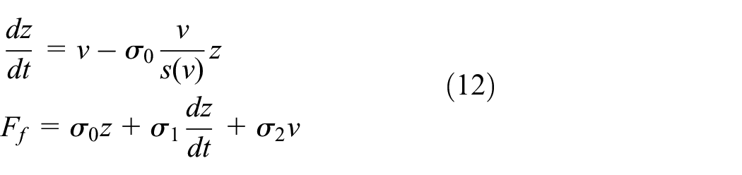
Where
Nevertheless, the LuGre model has some limitations, such as the inability to measure the state variable z and the challenge in verifying the microscopic damping coefficient through experimentation.
In summary, while the modeling, analysis, and identification of critical coefficients in friction models have become relatively developed, some achievements have also been successfully applied to compensate for the effect of frictional forces in feed systems. However, it is still not feasible to model and scrutinize the friction forces over the entire course of the feed system’s operation. The associated parameters used in existing friction models are also affected by other factors such as temperature, humidity, and rail lubrication condition which can cause unpredictable disturbances to the path of the feed system during point-to-point motion.
The feed system’s operation is subject to various disturbances such as cutting forces and external vibrations, which further complicates the position deviation during point-to-point motion.
Cutting force is a multi-frequency harmonic component that arises during the operation of the feed system, and milling force is one such example. The magnitude of cutting force is influenced by several factors, including cutting depth, cutting width, spindle speed, and feed rate. Additionally, the cutting force coefficient is primarily determined by the tool and the workpiece material, affecting the cutting force during the machining process. Furthermore, the tool’s geometrical parameters, such as helix angle, number of teeth, and tool corner radius, play a significant role in the time and frequency domain characteristics of the cutting force. 40 The simulated X-directional cutting force of a full-tooth straight-line milling with a diameter of 16 mm is shown in Figure 5.

Predicted and measured cutting force of ball-end milling.
Accurately predicting cutting forces can be challenging due to various factors which include precise identification of cutting force coefficients, and the effect of tool wear on the forces. Furthermore, the machining process can cause vibrations in the mechanical parts which can also affect the feed system’s positioning accuracy.
Parameter uncertainty
The machining and assembly of machine tool components are prone to several errors and deviations, resulting in system components that do not fully conform to design specifications. These factors contribute to the uncertainty associated with the parameters of the mathematical model, which may differ from their idealized counterparts obtained during design and simulation. AC servo systems are particularly sensitive to variations in the operational conditions that can alter the system’s electrical parameters, including the coefficients of motor resistance and inductance, which may further be impacted by temperature fluctuations. There is also potential for uncertainty when identifying the system’s operational model using system identification techniques due to the method’s inherent limitations.
Model uncertainty
Machine tool feed drive systems are mechatronic systems that exhibit complex dynamics, requiring simplified geometric models with appropriately representative characteristics. Joints in these systems play a critical role, but to date, no universally accepted approach exists for analyzing their dynamic characteristics. Common modeling techniques, such as the finite element method and the equivalent material method, tend to oversimplify the joint motion. Furthermore, uncertainty arises as no widely recognized modeling method for damping and friction mechanisms in mechanical dynamic systems has been established, and these are usually represented as proportional damping or friction force models. This results in a mathematical model of the controlled object in the feed system of the machine tool that is subject to uncertainty.
Parameter uncertainty is a well-studied phenomenon that typically involves one or more parameters in the controlled object’s model being represented by a random distribution. Representing model uncertainty using traditional dynamics models or other control models is challenging, particularly due to factors such as system simplification and equivalence. Hence, a random matrix method is presented for representing non-parametric uncertainty and characterizing model uncertainty factors in the system. 41
As an example, the general dynamic Equation is as equation (13):
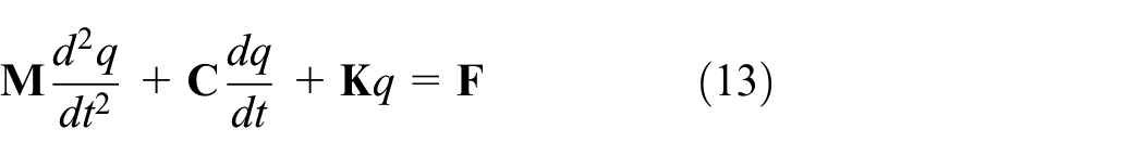
The equation (13) is an ideal dynamic Equation, which can be considered as an average model during practical application as equation (14).

Define the scattering parameter as

Where
Therefore, the Cholesky factorization of the mean matrix yields an upper three-bound and lower triangular matrix product of the form. It’s shown in equation (16):

Let

Taking an 8-degree-of-freedom spring-mass dynamical system as an example, neglecting the effects of damping and friction, the model is a linear time-invariant dynamical system in the absence of external excitation, and the frequency response function of the average model is expressed as equation (18)

The frequency response function of the uncertainty model is expressed as equation (19):

The system acceleration spectrum is defined as equation (20):

The ideal simulation dynamic parameters of the system are as equation (21):

The upper envelopes and averages of the acceleration spectra were solved for 512 sets of random samples based on Monte Carlo analysis with scattering parameters of 0.02, 0.05, and 0.1, respectively, as shown in Figure 6, which is compared with ideal model:

Acceleration spectra diagram for different scattering parameters
Simulation case analysis
Simulation system settings
This study aims to examine the effect of various uncertain factors on a single-axis linear motor feed system. For this purpose, an in-depth analysis of uncertainty factors is conducted using the feed system as an example. Specifically, the research simplifies and equates the structure of the motor feed system to establish a six-degree-of-freedom feed system model, The sketch of the linear motor feed system is shown in Figure 7. the model is shown as in Figure 8.

The sketch of linear motor feed drive system.
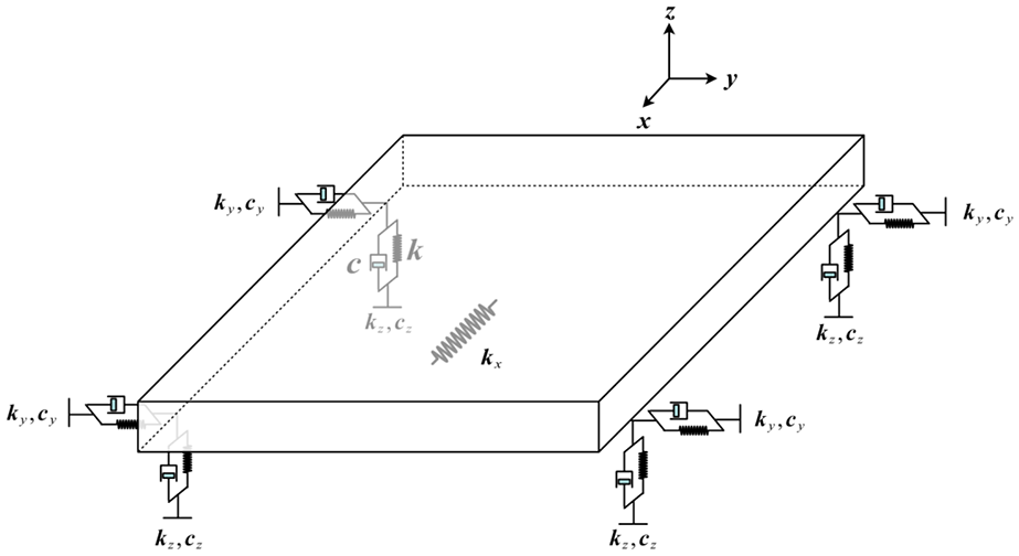
Linear motor worktable dynamic model.
Based on the feed system dynamics model shown above, its specific parameters are shown in Table 1. It is also assumed that the system damping is a general proportional damping, so the linear motor feed system dynamics model under ideal conditions can be obtained as shown in equation (22).
Parameters of the feed drive system.


Simulation results and analysis
The analysis examines the impact of disturbance uncertainty on the system’s output characteristics. The feed system’s actual operating conditions entail that external disturbance could be viewed as the amalgamation of multi-source harmonics. Consequently, the simulated thrust would be equivalent to the sum of multi-frequency and multi-amplitude harmonics. Notably, the system’s deterministic thrust affects only the feed direction. Thus, the expression for the deterministic thrust is as equation (23):
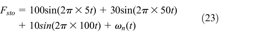
The
In practical conditions, it is more common to have a different type of random disturbance, which is the combined force of deterministic thrust and random noise. Monte Carlo simulations of the random thrust and the resulting dynamical system output characteristics are conducted based on such disturbances. The mean and variance of the random thrust, as well as the mean and variance of the system output response, obtained from 512 simulations are shown in Figure 9.

Random thrust and system response (a) output mean and (b) output variance.
This paragraph discusses the impact of both parameter uncertainty and model uncertainty on the output characteristics of system dynamics. The output characteristics of the system under the conditions where only parameter uncertainty and where both parameter and non-parameter uncertainties exist are compared. With regards to low frequency thrust input, the mean and variance of the system’s output under different conditions are shown in Figure 10, considering the thrust force received by the system in the feed direction as

Output response: (a) output mean under low frequency, (b) output variance under low frequency, (c) output mean under high frequency, and (d) output variance under high frequency.
Analyzing the effects of disturbance uncertainty, parameter uncertainty, and model uncertainty on the output characteristics of a dynamic system, we can determine that when the disturbance is characterized as a combination of deterministic harmonic thrust and stochastic white noise, it can be expressed as equation (23).
The output characteristics of the system under the condition of shared parameter and non-parameter uncertainty are shown in Figure 11. Comparing Figure 11 with Figure 9, it is evident that the parameter and model uncertainties of the system significantly affect the mean and variance of the output. Compared with the output characteristics of a dynamic system subject only to random perturbations, the high-frequency component of its output mean is significantly weakened, and its dominant harmonic frequency manifests as a low-frequency component. In addition, its output variance exhibits an order of magnitude increase after reaching basic stability.
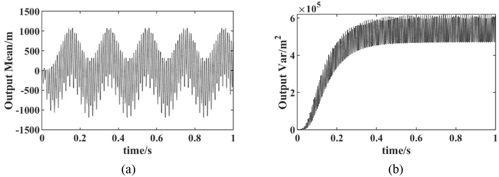
Output response for random thrust: (a) output mean with combined uncertainty and (b) output variance with combined uncertainty.
Combining with the definition of equation (4), the evolution law of uncertainty indicators of the output response under the evolution of uncertain parameters is analyzed. By changing the power of the random white noise in the input harmonic, it can be seen from Figure 12(a) and (b) that the impact of a single perturbation uncertainty on the uncertainty indicator of the output response is not significant. The input white noise energy will partially affect the mean and variance indicators of the output response, but the amount of change is small, basically maintaining the same level and the amount of change is no more than 5%. It can be deduced from Figure 12(c) and (d) that changing the divergence parameter of the uncertainty of the dynamic system model will significantly affect the mean and variance indicators of the output response. At present, the relevant research on feed system uncertainty mainly focuses on the field of disturbance uncertainty and parameter uncertainty. From the conclusion of Figure 12, it can be found that the intensity of the random noise component in the perturbation actually has a limited effect on the statistical characteristics of the dynamical system response. Compared with the existing research, this paper mainly increases the influence of model uncertainty, or non-parametric uncertainty, and it can be found that the parameters of model uncertainty will significantly affect the statistical characteristics of the system output response, when the divergence parameter increases from 0.02 to 0.2, the response mean norm will decrease by about 82%, and the response variance norm will decrease by about 71%, and when the divergence parameter is 0.05, the response variance norm will increase by 50%. This just proves the importance of introducing model uncertainty in this paper.

Evolution of uncertainty indicators with respect to uncertainty parameters: (a) uncertainty mean indicator for different noise powers, (b) uncertainty variance indicator for different noise powers, (c) uncertainty mean indicator for different scatter, and (d) uncertainty variance indicator for different scatter.
After further analyzing the impact of the divergence parameter on the uncertainty index, the time-domain response of the dynamic system output under different divergence parameters is compared, as shown in Figure 13. As the divergence parameter increases, the system output mean becomes “flatter,” and its output response variance is significantly reduced. It can be considered that as the divergence parameter increases, the impact of model uncertainty on the random characteristics of the system output response gradually increases.

Output response on different scatter: (a) output mean for different scatter and (b) output var for different scatter.
Conclusion
Existing research on motion accuracy of feed systems predominantly focuses on traceability, analysis, and improvement of deterministic error, while paying little attention to random error. This paper aims to address this gap by undertaking three tasks for the uncertain motion accuracy of single-axis feed systems. Firstly, to define the uncertainty motion accuracy of the feed drive system, the paper differentiates two categories: static and quasi-static error and dynamic error. Secondly, the ISO standard is examined with respect to the uncertainty of the static and quasi-static errors of the feed drive system. The definition of positioning accuracy and positioning repeatability already encompasses random errors, which can serve as the motion accuracy uncertainty index directly. Lastly, for the dynamic error, this paper selects the mean and variance of the system’s following error as the motion accuracy uncertainty index.
The article addresses three critical sources of uncertainty in feed systems: disturbance uncertainty, parameter uncertainty, and model uncertainty. Concerning disturbance uncertainty, the study examines the characteristics of multi-frequency and multi-source disturbances like friction and cutting forces that arise from the feed system’s actual working conditions. Furthermore, the paper leverages the random matrix method to characterize model uncertainty. Finally, the effects of these three uncertainty factors on the six-degree-of-freedom linear motor feed drive system’s output are analyzed based on its dynamics model. The Monte Carlo simulation method is utilized to compare the mean, and variance of the system output under different uncertainties, and confirm the impact of the uncertainty factors on the system’s motion accuracy uncertainty. The simulation results show that compared with the traditional parameter uncertainty, the model uncertainty will significantly affect the response variance of the dynamical system under low-frequency excitation, and the steady-state variance can be increased by about 1.5 times, while the mean response under high-frequency excitation is 50% and the response variance is 75%. Comparing the effects of the three uncertainties, the divergence parameter has the greatest influence on the output uncertainty of the dynamic response of the feed system, with the change of the mean index reaching 80% and the variance index changing by 70%.
Based on the research conclusions of this paper, the main work in the follow-up work considers to explore the control optimization method for the uncertainty of the position deviation of the feed drive system, improve the mean and variance of the following error in the operation of the feed drive system, and improve the dispersion of the following error.
Footnotes
Handling Editor: Chenhui Liang
Declaration of conflicting interests
The author(s) declared no potential conflicts of interest with respect to the research, authorship, and/or publication of this article.
Funding
The author(s) disclosed receipt of the following financial support for the research, authorship, and/or publication of this article: The work was supported by National Natural Science Foundation of China (Grant No. 52075426).