
Abstract
This study presents an optimization method to design the suspension properties associated with low-damped carbody oscillations for high-speed railway vehicles. In this method, the least damping ratio for the low-frequency modes in the entire service speed range and the critical speed for a worn wheel are proposed for the design objectives. Based on the linearized vehicle model, a genetic algorithm is applied to determine the optimal suspension properties to maximize the least damping ratio while maintaining the critical speed above the desired speed. The optimization results show that the proposed method can enhance lateral ride comfort by eliminating the region where the least damping ratio of the carbody mode decreases excessively and securing a constant for the entire service speed range. The least damping ratio was improved from approximately 5.7% to 15.6% and the critical for the worn wheel increased from approximately 430 to 499 km/h. Parametric studies are conducted to investigate the influence of the tolerances of the suspension properties, and the results provide useful information regarding the manufacture of suspension elements and assembly of the bogie system. The validity of the optimized suspension properties is verified from the simulation results using railway vehicle dynamics software.
Introduction
Low-damped carbody oscillation, which is caused by the coupled mode between sinusoidal motions of the bogies and sway or yaw motion of the carbody,1–3 sometimes degrades ride comfort even if the instability limit of a railway vehicle is not exceeded. 2 It has been recognized that this phenomenon occurs at relatively low vehicle speeds, and disappears at high speeds beyond the resonance zone 3 ; however, in some countries where high-speed railways are widely operated, it is reported that the deterioration of ride quality owing to the carbody oscillation also occurs in high-speed vehicles even when they are traveling above mid-speeds.3–5
This carbody oscillation can be suppressed by increasing the damping ratio of the coupled mode, and several measures have been introduced based on modified suspension properties.3–6 However, these suspension properties affect the lateral stability, safety, curving performance, and ride comfort, and some of their performances are conflicting; they should be carefully designed to balance each performance. As high-speed railway vehicles typically operate on large curves, their curving performance is generally not a priority. Thus, it is more important to balance lateral stability and ride quality on a tangent track.
Optimization techniques have been considered effective in compromising conflicting performances in the design process of suspension properties. He and McPhee 7 introduced a two-loop method using a genetic algorithm (GA) and sequential quadratic programing (SQP) with multibody dynamic simulation software to optimize the lateral stability of railway vehicles and investigated the cliff phenomenon, in which the critical speed changes dramatically with a small change in suspension stiffness. They also proposed a methodology for multibody systems using a hybrid multidisciplinary optimization method. 8 Nishimura et al. 9 presented a design strategy for optimizing the vertical stiffness and damping ratio of primary and secondary suspensions, to minimize the objective function consisting of the sum of the cost functions, such as carbody vertical acceleration, suspension travel, and wheel–rail interaction. Martowicz et al. 10 suggested a response surface method with a GA to enhance the comfort index by optimizing the stiffness of the primary and secondary suspensions. The mass of passengers was assumed to be an uncertain parameter, and the worst scenario of variation in the mass of passengers was considered as the objective function. Johnsson et al. 11 introduced a Pareto optimization method to enhance the safety and comfort of high-speed railway vehicles. The objective functions of safety and comfort were calculated from the response of a train model, constructed using multibody dynamics software, for lateral irregularities modeled by a stationary stochastic process. The sensitivity of the optimal solution was also investigated for train speed, worn wheel profile, load, and friction coefficients. They expanded their research to three objective problems, including the rate of wear of the wheel and rail expressed as the wear number. 12 They also suggested some adaptive control strategies based on the analysis of Pareto fronts for the variation in vehicle speed. Bideleh Mousavi et al. 13 presented a multistep methodology for improving the computational efficiency of Pareto optimization. Five scenarios with different track radii and vehicle speeds were applied to the multibody dynamics software to calculate the objective functions, and the advantages and disadvantages of the asymmetric suspension system were reported. The robustness of Pareto optimized values was also investigated with respect to the uncertainty of suspension properties owing to the manufacturing tolerance of ±25%. 14 Yao et al. 15 proposed optimal suspension properties for hunting stability robustness, defined as running speed robustness, suspension parameter robustness, and equivalent conicity robustness. The multi-objective function comprises the damping ratio of the 25 DOF linearized vehicle model at each robustness index. The K-Means clustering method was adopted to categorize a large number of Pareto fronts into six groups. Based on the analysis of the characteristics of each group and the corresponding Pareto sets, matching rules for the key suspension properties were suggested. They also suggested a method for the centralized optimization of key bogie suspension parameters based on vehicle lateral robust stability using damping ratios at vehicle speeds of 250 and 350 km/h. 16 Low and high equivalent conicities were applied for each vehicle speed.
Most previous studies applied objective functions with respect to a single or several vehicle speeds to increase ride quality and presented significant results. However, this method is not suitable for the problem of low-damped carbody oscillation because the low-damped carbody oscillation occurs at a certain speed range, and the width of the range and the location in the entire vehicle speed range depend on vehicle characteristics such as suspension properties and wheel–rail contact characteristics. For example, assume that the damping ratio of the carbody modes at a certain vehicle speed is selected as the objective function because the damping ratio has the smallest value at this vehicle speed with current suspension properties; however, once the optimization process begins, the vehicle speed at which the damping ratio has a minimum value is continuously changed because the suspension properties are changed at every iteration of the optimization process. Thus, although the damping ratio at that vehicle speed can be enhanced, a low-damped mode may still exist owing to the new minimum damping ratio at another vehicle speed.
The low-damped carbody oscillation can be effectively improved when the damping ratio of the related mode has an appropriate value for the overall vehicle speed. Thus, in this study, the least damping ratio in the service speed range of a railway vehicle, instead of specifying vehicle speeds, is proposed as an objective function for the low-damped carbody oscillation. This method updates the new least damping ratio with each iteration. When the current least damping ratio is no longer the minimum value, a new one is found and improved from the next iteration. Thus, the suspension properties can be optimized to maintain the damping ratios of the carbody modes above an appropriate value for the entire range of service speeds. The lateral stability of a railway vehicle, which usually refers to the bogie hunting stability, often conflicts with the lateral ride quality. When the vehicle speed is higher than the critical speed, bogie hunting occurs, which can directly lead to the rapid deterioration of vehicle safety indicators and the corresponding risk of railway vehicle operation. 3 Thus, it is very important to minimize the influence on the critical speed in optimizing the suspension properties to suppress low-damped carbody oscillation. Because the critical speed typically decreases under high-equivalent conicity conditions such as worn wheel profiles, the critical speed, particularly for a worn wheel condition, was considered as a design constraint or the second objective.
A linearized model was used to calculate the dynamic characteristics of the vehicle, such as damping ratios and damped natural frequencies, because the proposed method requires a slightly larger amount of calculation. In addition, linear computations are useful for concept investigation, parametric studies, and design optimization, although they cannot represent all the characteristics of a railway vehicle.2,5 The influences of the manufacturing tolerance of the suspension properties on the damping ratio of the carbody mode and the critical speed for the worn wheel condition were investigated through parametric studies. The effectiveness of the optimized suspension properties was verified from simulation results using railway vehicle dynamics software.
Suspension property design
Vehicle model
A 17 degrees-of-freedom (DOF) linearized model was applied to design the suspension properties and estimate their performance. This model was established in a previous study
5
to investigate and solve the low-damped carbody oscillation of the M1 car of the HEMU-430X, a high-speed electric-multiple-unit experimental train in Korea. As shown in Figure 1, the vehicle is composed of a carbody and two bogies, and each bogie has two wheelsets. The ends of each wheelset were assembled with journal boxes that were connected to the bogie frame with the primary suspension consisting of rod bushes (

M1 car of HEMU-430X; schematic model in (a) rear view, (b) top view, and (c) real feature of front bogie.
As the vehicle model was linearized for small perturbations at equilibrium points, high-order terms were neglected, and the wheelset’s roll motion was constrained by the equivalent conicity and lateral motion of the wheelset. 5 Thus, the linearized vehicle model has 17 DOFs (four wheelsets with two DOF, two bogie frames with three DOF, and one carbody with three DOF).
Because the state-space equation of the linearized vehicle model has been studied by various researchers,4–6,11,12 this study briefly introduces its configuration:

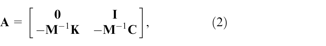

for
The damped natural frequency (


Table 1 lists the wheel–rail contact properties for calculating the creep forces and moments in the linearized vehicle model. New and worn wheel conditions were acquired from the contact geometries between the new and worn XP55 wheels and the new 60E1 rail with 1/20 inclination. The worn wheel had higher equivalent conicity and creep coefficients than the new wheel.
Wheel–rail contact properties in the linearized model.

Design variables, objective function, and constraint condition
As the longitudinal stiffness of the primary suspension and the series stiffness of the yaw damper mainly affect the magnitude of the yaw directional stiffness of the bogie, which is important for reducing the carbody oscillation, 5 these two suspension properties should be included in the design variables. However, to secure the critical speed for the worn wheel, other suspension properties such as the lateral stiffness of the primary suspension, and damping coefficients of the yaw and lateral dampers can also be considered. First, five suspension properties were selected as design variables, as expressed in equations (6) and (7).


where


The objective function is defined as the least damping ratio of the carbody mode over the entire service speed range and is expressed as follows:

where
A constraint condition based on the critical speed was applied to ensure the lateral stability for the worn wheel condition. In this study, the critical speed
Optimization and results
As shown in equations (1)–(5) and (10), because multiple calculation steps are required to obtain the values of the objective and constraint functions, it is likely that the two functions are discontinuous or have several local minima for the design variables. Thus, stochastic optimization techniques are more advantageous than gradient (numerical or analytical)-based techniques for optimizing the proposed objective function. In this study, a GA, which is a widely used stochastic algorithm, was applied. It is known to be highly reliable for global optimization and particularly useful for complicated problems.7,8 However, because the results in real implementations often depend on the option settings, 13 two types of optimization problems were solved as summarized in Table 2 and their validity was verified through comparison with each other. SO and MO in Table 2 denote constrained single-objective and unconstrained multi-objective problems, respectively. Thus, optimization was performed for all four cases.
Optimization problems.

Figure 2 shows the optimization results for CASE I when


Optimization results for five design variables: (a) optimal result of SO and Pareto fronts of MO (least damping ratio: ○ and critical speed for the worn wheel: •) and (b and c) optimal design variables of SO and Pareto set of MO.
As shown in Figure 2(a), the least damping ratio of the carbody mode (○) and critical speed for the worn wheel have a contradictory relationship with the bogie’s yaw directional stiffness, and the results of SO (Δ) lie on the Pareto fronts of MO despite the different GA options of population size, function tolerance, and stall generation. This implies that it is significantly difficult to obtain better optimized results than those of the SO under the given boundary and constraint conditions. The least damping ratio of the carbody mode and critical speed for the worn wheel were estimated to be approximately 19.5% and 460 km/h, respectively. Figure 2(b) presents the results of the design variables of the SO and the Pareto sets of the MO, which are expressed using Yt and Yr. The stiffness of the SO was optimized to place its Yr at the minimum Yr value of the MO, which means that the optimization was performed to reduce and increase the stiffness of the primary and secondary suspensions, respectively. Figure 2(c) shows the ratio of Yt to
Figure 3(a) shows the optimized results for CASE II. In the results of SO, the least damping ratio of the carbody mode was approximately 15.6% lower than that of the CASE I, whereas the critical speed for the worn wheel was approximately 499 km/h higher than that of CASE I, despite having the same

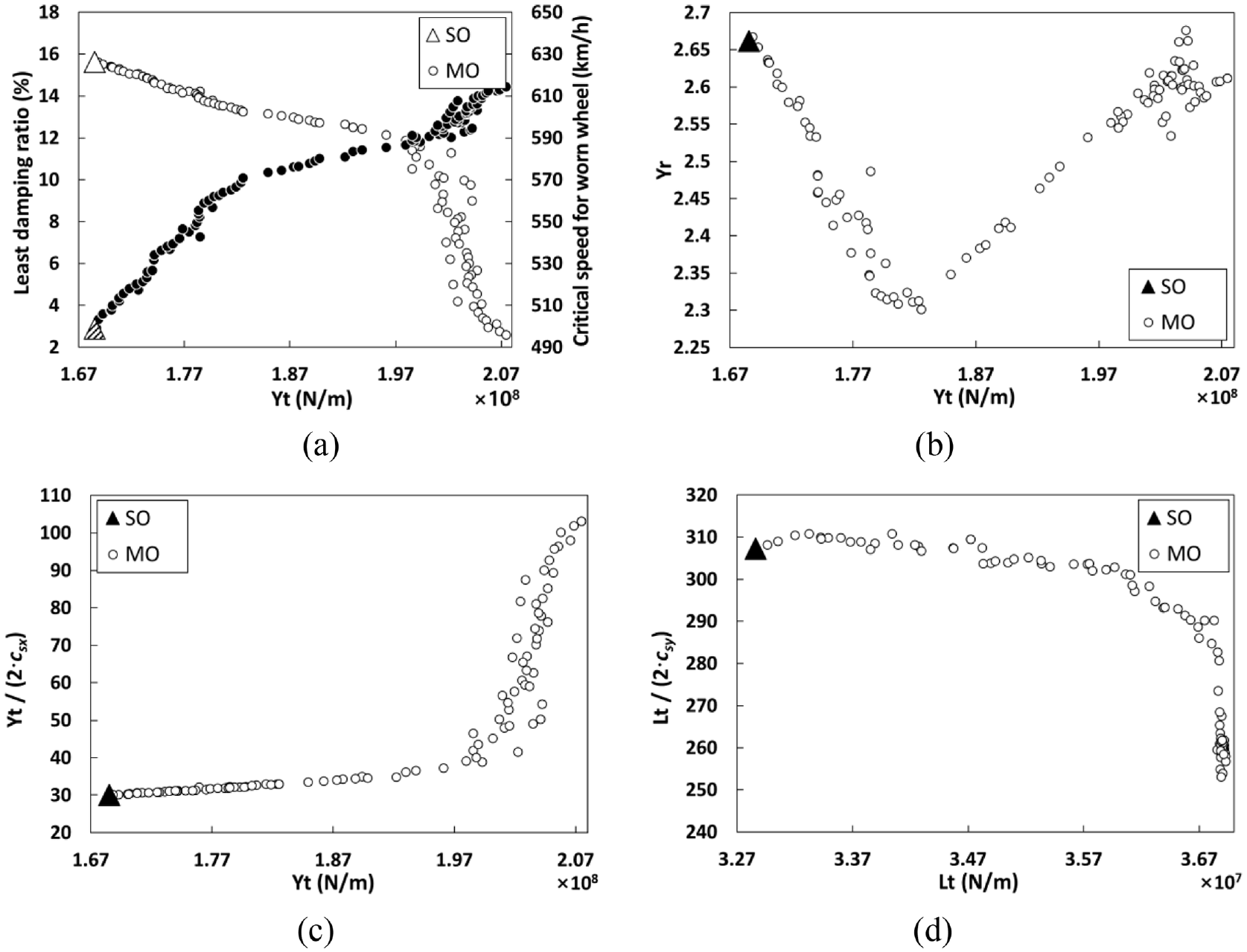
Optimization results for six design variables: (a) optimal result of SO and Pareto fronts of MO (the least damping ratio: ○ and critical speed for the worn wheel: •) and (b–d) optimal design variables of SO and Pareto set of MO.
Figure 4 shows the least damping ratios and modal frequencies of the M1 car based on the application of the optimized suspension properties. In Figure 4(a), there is no vehicle speed at which the least damping ratio of the carbody mode decreases significantly. In CASE II, the least damping ratio decreased slightly between approximately 160 and 380 km/h, and the modal frequency increased with increasing vehicle speed, which was caused by the remaining coupled mode between the sinusoidal motion of the bogies and the upper sway of the carbody. However, this oscillation mode is expected to be effectively restricted owing to its sufficient damping ratio. CASE I had an almost constant least damping ratio regardless of the vehicle speed because its dominant mode was the lateral motion of the carbody, as shown in the modal frequency in Figure 4(a). The least damping ratio in the bogie mode for the new wheel is shown in Figure 4(b). As the least damping ratio of the bogie mode for each case exceeded 5% even at a vehicle speed of 540 km/h, the critical speed for the new wheel was estimated to be sufficiently secured in all cases. Figure 4(c) shows the least damping ratio of the carbody mode for the worn wheel condition. Over the entire speed range, CASEs I and II exhibited constant damping ratios, similar to those of the new wheel. However, the least damping ratio of the carbody mode for the original suspension remarkably increased and had a value similar to that of CASE I. The modal frequency for the worn wheel implies that the change in the wheel–rail contact parameters changes the dominant mode from the coupled motion between the bogies and the carbody to the lateral motion of the carbody. Figure 4(d) shows the least damping ratio of the bogie mode for the worn wheel. The critical speeds were approximately 430, 460, 499 km/h for the original suspension, CASE I and CASE II, respectively. However, based on the least damping ratio of 5%, the critical speed had the lowest value in CASE I, approximately 270 km/h, followed by CASE II, 355 km/h and the highest value, 375 km/h in the original suspension properties.

Least damping ratio and modal frequency of M1 car along the vehicle speed: (a) carbody and (b) bogie modes for the new wheel condition, (c) carbody and (d) bogie modes for the worn wheel condition.
Influences of suspension property tolerances
To apply the optimized properties to manufacturing suspension elements, it is important to investigate the influence of manufacturing tolerances on the design results and constraint conditions, particularly when they have contradictory relationships with each other. Generally, in the manufacturing or maintenance process of the bogies, suspension elements with similar values for the same type are assigned to each bogie. For example, the stiffness of rod bushes in one bogie is similar to each other and the characteristics of the yaw dampers in one bogie are similar to each other, but slight differences from those in other bogies are acceptable if they are all within the allowable tolerances. The variation in the least damping ratio according to the changes in Yt, Yr, and Lt indicates that another guide is required to apply the suspension elements to the bogie, although they are produced within their allowable tolerances.
Figure 5 shows the variation in the least damping ratio of the carbody mode for CASE I, and it was assumed that the changes in Yt, Yr, and Lt only affect the parameters of rod bushes, yaw and lateral dampers, and the corresponding parameters can be calculated by combining equations (11)–(13). The result of SO is located in the high damping region close to O.B., in which the critical speed for the worn wheel does not satisfy the desired speed. In Figure 5(a), the grid with solid lines represents the area where the least damping ratio can be changed by ±20% tolerances of

Variation in the least damping ratio of the carbody mode for CASE I according to: (a) Yt and Yr, and (b) Yt and
Figure 5(b) shows the influence of the damping coefficient
The variation in the least damping ratio of the carbody mode for CASE II exhibits characteristics similar to those of CASE I, as shown in Figure 6(a) and (b). However, it is advantageous to control the tolerances more strictly because the carbody oscillation may not be effectively reduced if the least damping ratio of the carbody mode, which is lower than that of CASE I, decreases further owing to the tolerances. As shown in Figure 6(c), the tolerance of the damping coefficient of the lateral damper

Variation in the least damping ratio of the carbody mode for CASE II according to: (a) Yt and Yr, (b) Yt and
Simulations
Several simulations were performed using VI-Rail, a commercial software for railway vehicle dynamics, to verify the proposed design. The critical speeds for the worn wheel were evaluated using a vehicle model, and the ride comfort indices for the new wheel were analyzed using a train model consisting of four vehicles. The wheel profiles used in the simulation have the same characteristics as those listed in Table 1. Additionally, the worn wheel has the equivalent conicity that decreases with lateral shift of the wheel, and its nonlinear parameter 18 is −0.0223.
Figure 7(a) shows the VI-Rail vehicle model, and Figure 7(b) to (e) show the responses of the first wheelset of each vehicle model for a ramp function of the lateral track irregularity. The critical speed for the original suspension was estimated to be 400–420 km/h. As stated earlier, for CASE I, the critical speed decreased remarkably when series stiffness was applied to the lateral damper. However, when only the damping coefficient is adopted for the lateral damper, the critical speed is expected to range between 440 and 460 km/h. In the simulation, a sufficiently high series stiffness yielded almost the same critical speed; however, it was not within the manufacturable range while maintaining the designed damping coefficient. As predicted from the least damping ratio of the bogie, the critical speed for CASE II was higher than that of the other conditions and was in the range of 490–510 km/h. Interestingly, the simulations present critical speeds that are very similar to those of the linearized vehicle model, which is presumed to be due to the declining equivalent conicity for the lateral movement of the wheel. Supercritical Hopf bifurcation often occurs under this wheel–rail contact condition. 18

Simulation results for the critical speed under the worn wheel condition: (a) M1 car model built with VI-Rail software, (b) original suspension, (c) CASE I with the series stiffness of the lateral damper, (d) CASE I without the series stiffness of the lateral damper, and (e) CASE II.
The lateral ride comfort was calculated using the lateral accelerations of the carbody measured on the floor in accordance with ISO 2631 when the train model traveled on a straight line of approximately 10 km with ERRI low rail irregularities. Figure 8(a) shows the measurement points of the lateral accelerations, and Figure 8(b) to (d) show the lateral ride comfort indices for each train model. Each shape of the marks, “□,”“⋄,”“Δ,” and “◯” indicates the train speed of 200, 250, 300, and 350 km/h, respectively. In addition, the color of each mark indicates the travel direction of the train model: blue indicates the left (Mc is a leading car), and red indicates the right (Tc is a leading car). The results show that ride comfort is not exactly proportional to the least damping ratio because of the difference between the frequency– and time–domain responses, some nonlinear characteristics applied to the VI-Rail vehicle model, and the difference in the measuring points. However, this was significantly improved owing to optimized suspension properties. The lowest index (best ride comfort) for the original suspension was 0.0523 at p1 of M4 when the train model traveled left at a speed of 200 km/h, and the highest index (worst ride comfort) was 0.2100 at p2 of Tc when the travel direction was left at a train speed of 300 km/h. For CASE I, p2 of Tc showed the lowest index (0.0272) in the travel direction of the right at a speed of 200 km/h, and p2 of M1 had the highest index (0.1070), when the train model traveled left at a speed of 350 km/h. For CASE II, the lowest index, 0.0289, appeared at p2 of Tc when the travel direction was on the right and the train speed was 200 km/h; the highest index was 0.1286 at p2 of M1 when the train model traveled left at a speed of 350 km/h. Thus, CASEs I and II improved the ride comfort by 48% and 45% for the lowest index and 49% and 39% for the highest index, respectively. Comparing the ride comfort of the M1, CASE I improved by 43% and 45% and CASE II improved by 37% and 34%, for the lowest and highest indices, respectively.

Simulation results for the ride comfort (ISO 2631) in lateral direction: (a) measurement points, (b) original suspension, (c) CASE I, and (d) CASE II. Marks, “□,”“⋄,”“Δ,” and “◯,” represent the train speed of 200, 250, 300, and 350 km/h, respectively. Blue and red colors denote the travel to the left and right direction, respectively.
The simulation results for critical speed and ride comfort indicated that the optimized suspension properties for CASE II were more suitable for actual implementation, although the ride comfort was slightly lower than that of CASE I. In CASE II, all the designed suspension properties were within the manufacturing range.
Conclusions
Low-damped carbody oscillations have been an interesting research area and challenge to be solved for railway vehicle dynamics engineers. In a previous study, the cause of carbody oscillation of the HEMU-430X was investigated, modification of some suspension properties was suggested, and its effectiveness was validated in a field test. 5 However, it had a limit that the influence on the lateral stability for high equivalent conicity owing to wheel–rail wear was not sufficiently considered. Hence, in this study, an optimization technique for the suspension properties was proposed to suppress the lateral carbody oscillation while maintaining or enhancing the lateral stability for the worn wheel.
The optimization results indicate that the least damping ratio defined in equation (10) can be an effective design target to suppress the low-damped carbody oscillation by eliminating the region where the damping ratio of the carbody mode decreases excessively and securing a constant least damping ratio for the entire service speed range, as shown in Figure 4(a). The optimization was performed with five design variables (CASE I) and six variables (CASE II). In CASE II, the series stiffness of the lateral damper was added because the lateral damper could not be manufactured with the designed damping coefficient of CASE I unless its series stiffness was lower than the current value. The lower series stiffness caused a deterioration of the critical speed for the worn wheel condition in the simulation. The series stiffness of the lateral damper plays an important role in securing the critical speed, because the lateral motion becomes the dominant mode of the bogie as the vehicle speed increases. However, its effects on the carbody mode, which were not described in this study, were found to be small.
The total stiffness of the bogie (Yt, Lt) and stiffness ratio (Yr) between the primary and secondary suspensions were introduced to efficiently compare the results of the constrained single-objective and unconstrained multi-objective optimizations and investigate the influence of the tolerances. The diagrams of Yt, Yr, and Lt can provide useful information when determining whether the manufactured suspension elements are applicable or when selecting the proper set of suspension elements for each bogie. To ensure the desired critical speed, it is important to construct a set of suspension elements such that Yt and Lt are increased but Yr is maintained or decreased. The change in the lateral and yaw damping coefficients affected the damping ratio of the carbody mode; however, it had a relatively small effect on the critical speed.
In the simulation, the optimized suspension properties exhibited the expected performance for lateral ride comfort and critical speed for the worn wheel. The ride comfort was improved by 48%–49% in CASE I and 39%–45% in CASE II. However, the critical speed for the worn wheel condition was approximately 370 km/h for CASE I. It can be increased to the desired speed by increasing the series stiffness of the lateral damper. However, this value is outside the manufacturable range. In CASE II, the critical speed was approximately 500 km/h.
Finally, the results of the optimization and simulation show that the optimized suspension properties achieved a significant improvement in the ride comfort and lateral stability for the worn wheel condition, and that the designed properties in CASE II can be a good suggestion for high-speed railway vehicles. For actual implementation, the manufacturing tolerances of the rod bushes and the series stiffness of the yaw and lateral dampers should be positive and managed more tightly than their commonly used tolerances in railway vehicle engineering. In a future study, a prototype of a high-speed bogie with optimized suspension properties will be constructed, and its performance will be evaluated using a roller–rig test stand.
Footnotes
Handling Editor: Chenhui Liang
Declaration of conflicting interests
The author declared no potential conflicts of interest with respect to the research, authorship, and/or publication of this article.
Funding
The author disclosed receipt of the following financial support for the research, authorship, and/or publication of this article: This work was supported by a grant from the R&D Program of the Korea Railroad Research Institute (PK2303D3), Republic of Korea.