
Abstract
MPW produces a high Lorentz force for welding through the interaction of magnetic fields between the working coil and outer workpiece. Therefore, the design of the working coil is crucial in the MPW process. In particular, it is important to understand and estimate the distribution of Lorentz force on the outer tube and the stress on the working coil. These factors greatly impact the efficiency of energy delivery and the durability of the process. The purpose of this research was to analyze the effect of coil design parameters on the Lorentz force and stress. The ultimate objective was to optimize these design parameters specifically for welding tubular workpieces; for this, an electromagnetic-mechanical FE-model was developed. The design parameters considered in this study included the angle, radius, and protruding length. The Lorentz force and stress were calculated based on these parameters. Notably, the response surface method (RSM) and sequential quadratic programing (SQP) were utilized to develop a prediction model and optimize the design parameters, respectively. The findings revealed that the protruding length and angle are significant design parameters. Consequently, a working coil was manufactured using the optimized design parameters, leading to a successful Al/Cu joint. These results emphasize the indispensability of optimizing design parameters to achieve high-quality joints.
Keywords
Introduction
Aluminum has advantages in terms of product weight reduction and manufacturing cost because it is significantly less expensive than copper and has a thermal conductivity comparable to that of copper. 1 Consequently, aluminum has been considered an alternative to copper in the refrigeration cycle, and its application is expanding to home appliances in the electronics industry, as shown in Figure 1.
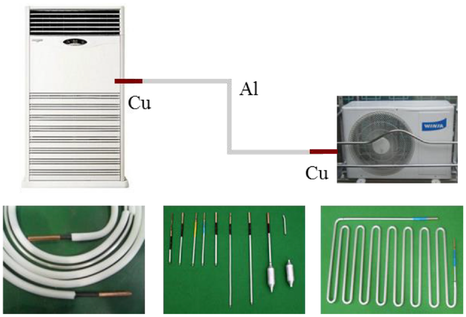
Al/Cu dissimilar joint for home appliances.
For these reasons, the electronics industry has recently begun considering weight reduction and processes for joining dissimilar materials as fundamental technological objectives. In addition, according to several studies, the use of aluminum, as opposed to conventional steel, will increase in the development of future materials. These trends indicate that the welding, joining, and fastening technologies of various materials will be of paramount importance in the future, and securing these technologies will likely ensure product competitiveness. 2 Consequently, attempts have been made to use numerous existing welding processes to weld multi-materials and mixed components. Due to the dissimilar properties of the multi-materials during welding, however, heat-based fusion welding processes typically result in defects such as solidification, cracking, porosity, oxidation, and transformation. These defects degrade the quality of the weld and generate environmental pollutants due to refrigerant gas leakage caused by corrosion. Therefore, it is necessary to develop a high-quality multi-material welding process. There are several solid-state welding processes available for dissimilar materials. Friction stir welding and explosive welding are well-known examples of solid-state welding. Yang et al. 3 conducted a numerical analysis of mass transfer and material mixing in friction stir welding of dissimilar weldments. Bhattacharya et al. 4 attempted to join aluminum alloy to DHP copper using friction stir welding. This process has the capability to produce high-quality joints between different combinations of materials. However, due to tool conditions, several types of defects may occur in weldments, such as thickness reduction and flash and keyhole defects. 5 Explosive welding utilizes explosive force to create a successful metallurgical bond between workpieces. Kumar et al. 6 reported on the welding of magnesium and aluminum alloys using an inclined arrangement in explosive welding, while Carvalho et al. 7 described the effect of the flyer material on the interface phenomena in aluminum and copper explosive welds. However, controlling the process parameters is difficult and experimental work can be unsafe. For this reason, the electromagnetic joining technique has been focused on the joining of dissimilar materials. Electromagnetic driven self-piecing riveting and MPW (magnetic pulse welding) are representative electromagnetic joining processes. Electromagnetic driven self-piecing riveting is a new joining process based on electromagnetic forming technology. The impetus of the riveting process is Lorenz repulsion from the high electromagnetic field, which impacts the rivet.8,9 Jiang et al. compared joining quality of electromagnetic driven self-piecing riveting with that of adhesive and hybrid joints for Al/steel structures. Their results showed that hybrid joints made using electromagnetic self-piecing riveting, and adhesive bonding, had excellent reliability and security. 10 Liao et al. 11 investigated effects of rivet arrangements on fatigue performance of electromagnetic riveted joints with Φ10 mm diameter rivets using quasi-static shear tests, fatigue tests, numerical simulations, and microstructural observations. The MPW is as a non-contact joining process, it is capable of producing defect-free, high-quality joints and is applicable to surface-treated materials. Notably, the MPW process uses only electromagnetic force, so it is capable of transitioning to a clean process without the hazards of conventional fusion welding processes. 12
Because the working coil is directly related to the quality of the weld, it is crucial in an MPW system. The working coil is responsible for providing the required electromagnetic force concentration on the outer tube. Therefore, finding an appropriate working coil design is crucial for the MPW of the workpiece. The parameters have a close relationship with electromagnetic interaction and workpiece energy delivery efficiency. Nevertheless, no theoretical analysis of the development of optimal working coils considering various design parameters has yet been conducted. However, factors of consideration can generally be put into two categories: the shape and the mechanical/electrical properties of the material. 13 Most commonly, compression, expansion, and flat working coils are utilized in the MPW process. The compression type is located outside the workpiece and is used for welding the flyer workpiece inward in a radial direction. The expansion type, on the other hand, is inserted within tubular workpieces and used for welding the workpiece outward in a radial direction. Flat (pancake) coils are spirally wound and can be positioned either above or below a sheet workpiece. Depending on the application, these working coils are manufactured with single- or multi-turn helical windings.
Working coils must have durability, manufacturability, cost/energy delivery efficiency, and safety, according to Imbert and Worswick. 14 However, the most important factor is energy delivery efficiency, as the MPW process employs only the Lorentz force to generate electromagnetic interaction between the working coil and flyer workpiece. Therefore, designing the working coil is a crucial step in the MPW process.
Typically, a multi-turn working coil with a field shaper is used to concentrate the high magnetic flux and produce a high Lorentz force for the process. 15 Park 16 attempted to fabricate axial and torque joints using a working coil with multiple turns and a field shaper to generate a full Lorentz force. Neugebauer et al., 17 in a simulation, also utilized a multi-turn coil for Al/steel tubular welding. A multiturn coil with a field shaper is, however, less efficient than a well-designed single-turn coil. Increasing the turns of a coil increases the discharge time during the high-velocity impact-welding process, so it is unsuitable for the welding process. Shribman et al.18,19 established the use of MPW for axisymmetric structures (i.e. tubes). Vanbenthysen 20 fabricated a tapered single-turn axisymmetric coil to concentrate the magnetic field.
As a result of the significant electromagnetic interaction between the working coil and the outer workpiece, induced by the current flowing through the working coil, rapid currents of opposite directions are produced on the surface of the outer workpiece. These opposing currents generate a Lorentz force on the outer workpiece and a repulsive force on the working coil, often leading to severe deformation of the working coil. Hence, it is crucial to ensure the durability of the working coil.
Since the MPW process utilizes only the Lorentz force generated by electromagnetic interaction, the finite element method (FEM) is generally used to analyze this process.21–24 However, previous studies have not focused on developing a prediction model for the Lorentz force and stress of the working coil based on the relationships between the design parameters. Additionally, there has been no optimization of the design parameters for the working coil. Therefore, the objective of this study is to develop a prediction model for the Lorentz force and stress of a single-turn working coil, as well as to optimize model design parameters for a high-quality Al/Cu tubular joint. To accomplish this, first, effects of design parameters on Lorentz force and stress of working coil were calculated under various conditions using the developed FE model. The prediction models were developed using response surface design (RSM), and the sequential quadratic programing (SQP) method was employed to optimize the design parameters. As verification, a designed working coil that uses the selected design parameters was employed to manufacture an AA1070/C12200 tubular joint. The quality of the Al/Cu tubular joint was evaluated through leakage and tensile tests.
Numerical works
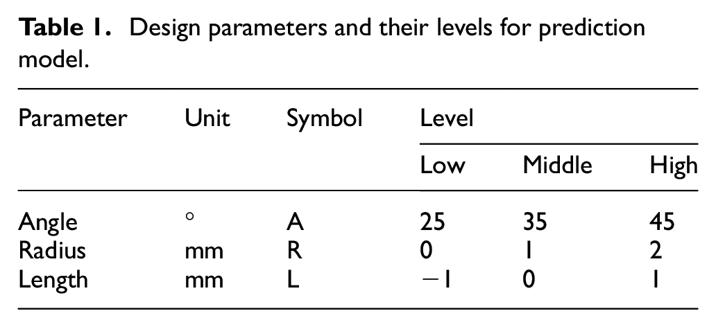
Variations in the working coils’ shape altered the distribution and direction of the Lorentz force and stress during the process. Due to the high electromagnetic interaction between the working coil and the flyer workpiece, caused by the current flowing through the working coil, fast currents in opposite directions are generated on the flyer workpiece surface. These opposite-directional currents generate Lorentz force on the flyer workpiece as well as repulsive force on the working coil, frequently resulting in deformation of the working coil. Consequently, ensuring the durability of the working coil is crucial. For an effective working coil design, the Lorentz force on the flyer workpiece and stress on the working coil during MPW were chosen as the response parameters. The three selected design parameters are illustrated in Figure 2, which shows a schematic of an axisymmetric working coil with the workpiece. The design parameters were chosen for a single-turn working coil: angle (A), edge radius (R), and protruding length (L). To analyze the effects of the design parameters, angle, radius, and length were varied from 15°, 0 mm, and −2 mm to 45°, 3 mm, and 1 mm, respectively. An easy way to estimate the response surface, central composite design (CCD), was employed, and a total of 20 simulations were designed to develop the prediction model. For three factors (

Design parameters for axi-symmetric working coil with workpiece.
Design parameters and their levels for prediction model.
Design of simulation condition by CCD.

Development of FE-model
A commercially available finite element software package, LS-DYNA, was used to simulate the transient electromagnetic-mechanical phenomena. LS-DYNA is an appropriate tool for investigating processing phenomena involving large deformations, sophisticated material models, and complex contact conditions, such as MPW.13,25,26 The Maxwell equations are solved using the FEM for solid conductors and the boundary element method (BEM) for the surrounding air. Figure 3 shows the FE model developed for this study. The electromagnetic FE-model was used to determine the electromagnetic forces acting on the outer workpiece through electromagnetic interaction in the electromagnetic-mechanical FE model for MPW. The calculated Lorentz forces were then applied as input loads to the mechanical FE model to simulate the high-velocity collision between the outer and inner workpieces. The MPW process involved high strain rate deformation processes; thus, it was necessary to input the Johnson-Cook material constant parameter values as material properties. 27 Therefore, the Johnson-Cook constitutive model was utilized to model the welding behavior. Johnson-Cook constitutive model, a combination of plastic strain and plastic strain rate, is shown in equation (1):
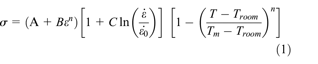
Where

FE-model for this study.

Inputted waveform.
Material properties for numerical works. 27

Chemical compositions of materials.

Verification of FE-model
Al/Cu welding was conducted to validate the developed FE-model. The design parameters of the working coil consisted of a 35° tapered angle, 1 mm edge radius, and 10 mm protruding length. The working coil was manufactured through precise wire cutting of C12200. For this study, we employed the MPC system manufactured by WELMATE Co., Ltd. The pulse power source comprised 10 capacitors connected in parallel; system discharged the capacitors to the working coil through a triggered switch unit. The total capacitance was 613 μF and the charge voltage was maintained at or below 14 kV, resulting in a maximum charge energy of 60 kJ. The welding condition matched the input values of the numerical simulation. The peak current, measured by a Rogowski coil, was 484 kA, and the gap between the workpieces was 0.8 mm. As shown in Figure 5, the joint contour was precisely measured with a FARO laser line probe after welding.

Laser line scanning to measure contour.
As shown in Figure 6(a), the Al/Cu joint created by MPW had a deformation length of approximately 11.2963 mm, as measured by the line scan in Figure 6(b). Specifically, displacement values of the flyer workpiece were measured and found to be 0.9301, 0.6070, and 0.7724 mm for the front, middle, and rear of the joint, as depicted in Figure 7(a). From Figure 7(b), the deformation length was calculated and found to be 11.8514 mm; this displacement was comparable to that found in the 3D scan data. These results demonstrate that the simulation and experiment results are consistent. Furthermore, they demonstrate the validation of the developed FE model for further analysis of the effects of design parameters on working coils using the developed model.
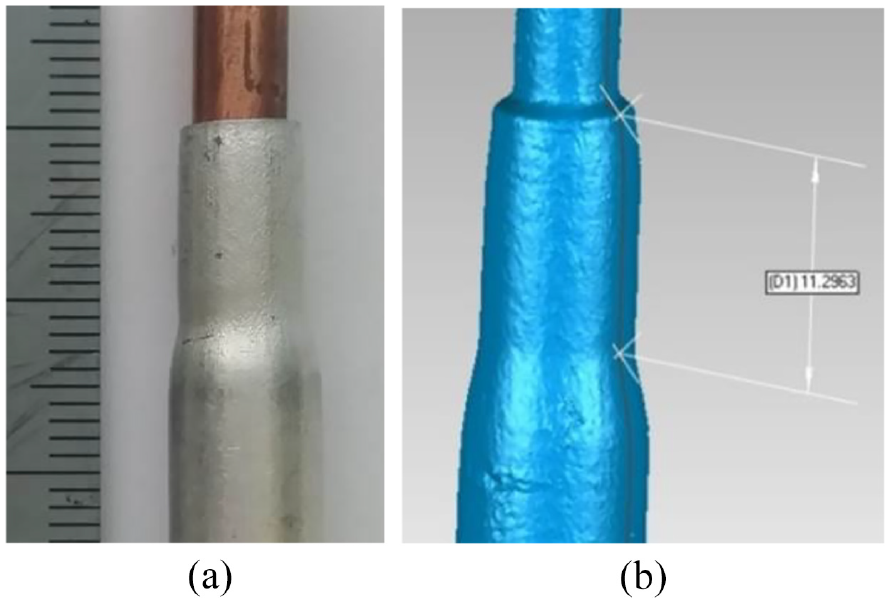
Al/Cu joint contour by line scan: (a) Al/Cu joint and (b) measured deformation length.

Comparison of FE-model and experimental results: (a) measured displacement by line scan and (b) displacement calculated by FE-model.
Results and discussion
Lorentz force
A large Lorentz force must be generated on the flyer workpiece for the high-velocity impact between the workpieces. Consequently, the developed FE model was used to calculate Lorentz forces under different design process conditions. The effects of the angle on the Lorentz force are shown in Figure 8(a). Increases in angle decreased the Lorentz force due to decreases in generated electromagnetic interaction between the working coil and the flyer workpiece, these decreases were attributed to electromagnetic field scattering. The Lorentz force was approximately 250 N when the working coil angle was 15°; the difference between the 15° and 45° angles was approximately 80 N. In contrast, the effect of edge radius was negligible. When the edge radii were 0, 1, 2, and 3 mm, the Lorentz forces were 210, 207, 213, and 235 N, respectively.

Effect of design parameters on Lorentz force: (a) angle, (b) radius, and (c) protruding length.
As shown in Figure 8(b), the difference of force between the radius edge values of 0 and 3 mm was 25 N. This indicates that the coil radius has a negligible effect on the Lorentz force. However, electromagnetic interaction decreased with increasing edge radii. As shown in Figure 8(c), the Lorentz force decreased dramatically as the protruding length increased. When the length was −2 mm, the Lorentz force was about 278 N, and the difference between −2 and 1 mm lengths was about 85 N. These results indicate that the protruding length is significantly more important than the other design variables. Figure 9 shows the distribution of Lorentz force on the surface of the outer workpiece.
Lorentz force with various design parameters: (a) angle: 15°, (b) angle: 45°, (c) radius: 0 mm, (d) radius: 3 mm, (e) length: −2 mm, and (f) length: 1 mm.
As shown in Figure 10, increasing the protruding length leads to a sharp decrease in the current density, thereby decreasing the Lorentz force. The density of current when the protruding length was −2 mm was calculated and found to be 2.57 A/m2. In contrast, when the protruding length was 1 mm, the calculated current density was 1.81 A/m2, resulting in a difference of 0.76 A/m2.

Current density with protruding length: (a) length: −2 mm and (b) length: 1 m.
Stress
When electromagnetic interaction occurs between the working coil and the flyer workpiece, it generates a high Lorentz force on the flyer workpiece, as well as a repulsive force on the working coil. Deformation happens when the applied repulsive force exceeds the yield point of the working coil. Consequently, the developed FE model was used to calculate stresses under various design process conditions. Figures 11(a) and 12 show the effects of angle on stress. The stress on the working coil with a 15° angle was approximately 260 MPa, while the stress with a 45° angle was about 110 MPa. Reducing the angle increased the stress on the working coil because the electromagnetic interaction intensified as the electromagnetic field concentration increased. As shown in Figure 10, the working coil experienced a strong electrical repulsive force as the electromagnetic interaction increased. Nevertheless, the edge radius and the protruding length did not significantly affect the stress on the working coil. Figure 11(b) illustrates the effect of the edge radius on the working coil. Due to the increased repulsive force, the stress slightly increased as the radius of the edge increased. For instance, with a 3 mm edge radius, the maximum stress was 121 MPa, and the minimum stress was approximately 100 MPa. As shown in Figure 11(c), the stress on the working coil was minimal despite variation in the protruding length.
Effects of design parameters on stress of working coil: (a) angle, (b) radius, and (c) protruding length.
Lorentz force with variation of angle: (a) angle: 15° and (b) length: 45°.
Development of prediction model
RMS is a mathematical and statistical method for analyzing the relationship between the input parameters and the output response. It saves the cost and time of simulations by reducing the overall number of required tests. Furthermore, it helps accurately identify and describe the effects of the interactions of independent parameters on the output when they are varied simultaneously. Tables 5 and 6 show analysis of variance values for the responses. Generally, the p-value is used to estimate whether F is large enough to indicate statistical significance. The meaning of the symbols used is: (DF) degrees of freedom, (Adj SS) Adjusted sum of squares, (Seq SS) Sequential sum of squares, (Adj MS) Adjusted mean squares, and (R-Sq) Coefficient of determination; “F” is the variance or the Fisher ratio of any factor, (Seq SS) is the pure sum of squares of any factor, and “P” is the critical probability. If the p-value is lower than 0.05, this indicates that the model is statistically significant. 28 As shown in Table 5, effects of linear terms and squared terms of angle and protruding length were statistically significant on Lorentz force. On the other hand, the two-factor interaction terms were insignificant. In addition, effects of linear terms and two-factor interaction terms on the stress of the working coil were significant, as shown in Table 6.
Analysis of variance for Lorentz force.

Analysis of variance for stress of working coil

As a model for predicting the Lorentz force and stress, a quadratic polynomial model was developed using regression analysis, as follows:


where A, R, and L refer to the angle, edge radius, and protruding length, respectively. The coefficients of determination (R2) of the developed prediction models are 97.74% and 85.12%, respectively. Figure 13(a) and (b) compare the simulation results and predicted values for Lorentz force and stress, respectively. The predicted values agree with the experimental results, with an average error of less than 10%.
Comparison between simulation results and predicted results: (a) Lorentz force and (b) stress of working coil.
Optimization of design parameter using SQP
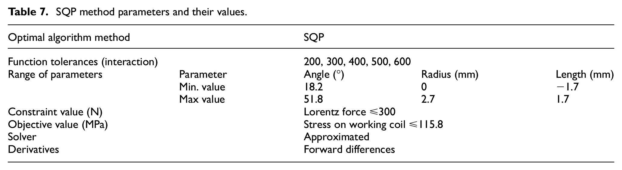
A working coil for tubular welding must be durable and ensure efficient energy delivery. To meet these requirements, SQP, one of the optimization techniques considered in this study, was employed to develop a high-efficiency working coil. The SQP method is a global optimization technique capable of performing accurately and efficiently on various nonlinear problems. Using a Quasi-Newton technique, the Hessian matrix of the Lagrangian function was updated for a significant iteration. This was then utilized to generate a quadratic programing subproblem to determine the search direction for a line search procedure. This study used MATLAB to implement the algorithm. 29 A quadratic polynomial model can be used to describe the problem of designing a working coil with efficient energy delivery and high durability. To avoid being trapped in a local optimum, 200–600 initial conditions were randomly generated to initiate the optimization process. In the programing phase, the objective function and constraints were formulated as equations and variables representing the Lorentz force and stress parameters to be optimized, as defined by equations (1) and (2). The minimum and maximum values of the three design parameters varied. The objective of the optimization was to limit the range of the Lorentz force and minimize the stress on the working coil. According to the ASTM E466 standard, a high cycle fatigue test was performed for C12200, as shown in Figure 14. The fatigue test estimated the maximum stress amplitude for maintaining 106 cycles to be 115.8 MPa. Table 7 shows the SQP method parameters and their corresponding values for this investigation. Table 8 shows the results of various interactions utilizing the SQP method. When the number of interactions reached 400, the constraint error was at its lowest (the constraint value was 299.447 N, and the stress was 156.345 MPa). However, in terms of durability, the stress was excessive. The required stress level was met in the 200 and 600 interaction cases.

C12200 S-N curve.
SQP method parameters and their values.
Results of various interactions using SQP method.
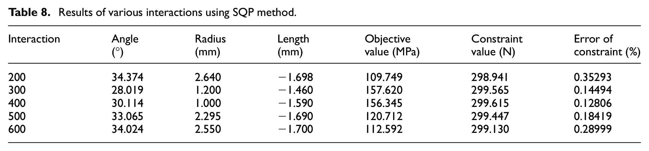
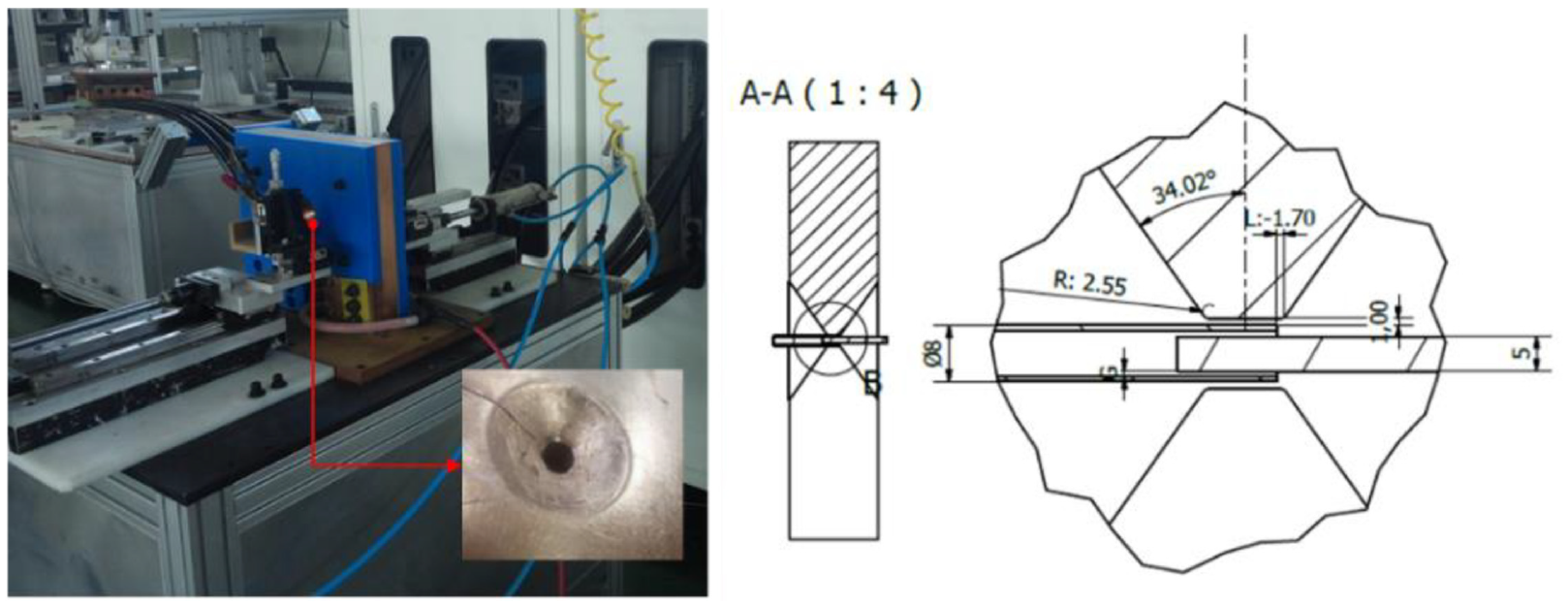
The stress values were 109.749 and 112.592 MPa, and the constraint errors were 0.35% and 0.28%, respectively. For this reason, an angle of 34.024°, a radius of 2.55 mm, and a protruding length of −1.7 mm were chosen to achieve 299.130 N and to ensure the durability of the working coil.
Validation test of optimized working coil
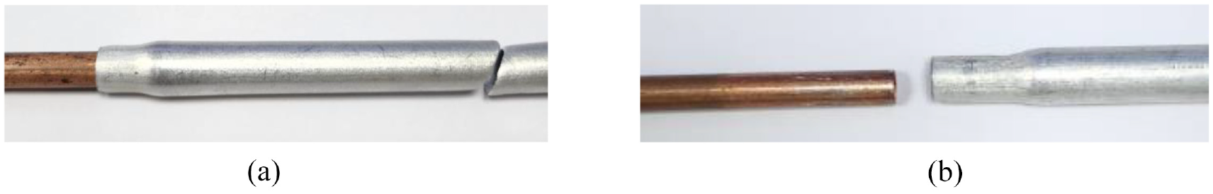
The optimized working coil was manufactured with C12200 through precise wire cutting. Figure 15 shows the MPW system with the working coil. As for the welding conditions, the peak current, the gap between workpieces, the frequency, and the protruding length were 484 kA, 0.77 mm, 27 kHz, and −1.7 mm respectively. To verify the optimized values, joint quality was compared with that from the non-optimized welding condition. For the non-optimized condition, the protruding length varied from −1.7 to 0.5 mm. As shown in Figure 16, the joint quality was evaluated based on the results of a tensile test with internal support for the Al tube and by leakage test; each experiment was repeated three times to ensure data reliability. Figure 17 shows the results of the tensile test. The joint broke at approximately 53 MPa at the Al tube, as shown in Figure 18(a), which shows that the strength of the joints is higher than the strength of the parent materials. On the other hand, the Al/Cu joint separated at approximately 6 MPa under non-optimized welding condition, as shown in Figure 18(b). Similarly, a burst in the Al tube, not in the joint, was observed as shown in Figure 19. The burst pressure of the Al tube was measured and found to be 185 kg/cm2; however, leakage was observed at 40 kg/cm2 for the joint manufactured under non-optimized welding condition. A wavy pattern was observed on successful dissimilar MPW weldments, as shown in Figure 20(a). In accordance with Cowan et al., 30 this wave formation is attributed to Kelvin-Helmholtz instability criteria. The materials are influenced by hydrodynamics during the joining process. When two fluids with different material properties and velocities interact, instabilities occur at the interface, resulting in the formation of interface waves through the Kelvin-Helmholtz instability mechanism. These interface waves cause reflected shock waves, which serve as sources of interference at the weld interface. In contrast, the Al/Cu joint manufactured under non-optimized welding condition separated during cutting, as shown in Figure 20(b). From these results, it can be confirmed that the designed working coil led to a successful Al/Cu tubular MPW joint. Although the optimization model may change with variations in the welding conditions, it can serve as a valuable reference for designing a working coil with good durability and energy delivery efficiency. Thus, this study can contribute fundamental data for designing working coils for MPW.
MPW system with manufactured optimized working coil.
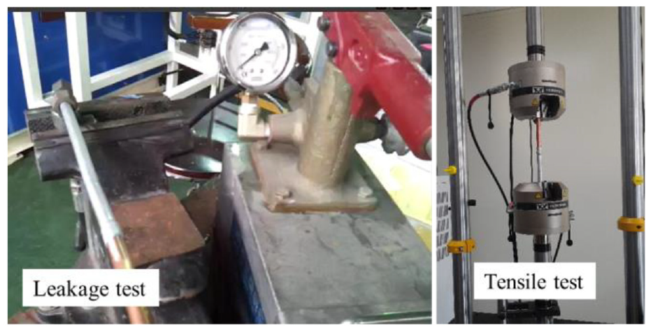
Setup for joint quality evaluation test.
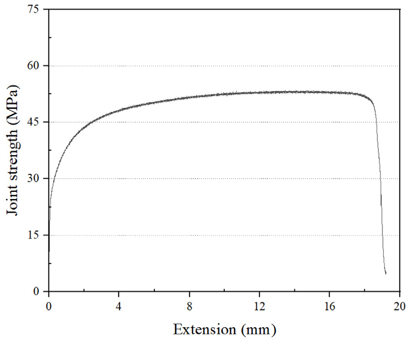
Al/Cu joint strength by optimized working coil.
Al/Cu joint by tensile test: (a) Al tube fracture: optimal condition and (b) separation of joint: non-optimal condition.

Al tube burst by leakage test.
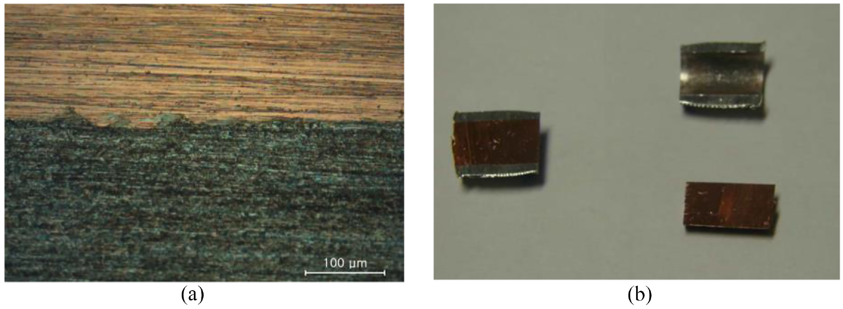
Observation of interface of Al/Cu joint: (a) interface of joint: optimal condition and (b) separation of joint: non-optimal condition.
Conclusion
After analyzing and optimizing the design parameters of a single-turn working coil, the following conclusions were reached:
(1) Using LS-Dyna, an electromagnetic–mechanical FE-model for a tubular MPW was developed. Simulation and experimental results were compared to validate the developed FE model and showed good agreement. Therefore, the developed FE model can be used to analyze the effects of the design parameters.
(2) The following design parameters were chosen for the single-turn working coil: angle, edge radius, and protruding length. The effects of the design parameters were analyzed using the developed FE-model. The effects of Lorentz force and stress on the working coil were calculated; results indicated that the protruding length and angle of the working coil were the most significant parameters in terms of Lorentz force and stress. As the protruding length increased, the Lorentz force on the outer workpiece decreased sharply.
(3) Using an RSM with three design parameters and two responses, prediction models for the Lorentz force and stress of the working coil were developed. To validate the developed prediction models, simulation results were compared with predicted results; high accuracy was obtained.
(4) Using SQP, the optimal design parameters were determined. Angle, radius, and protruding length were chosen to attain the maximum Lorentz force and minimum stress under the fatigue limit of the working coil. The developed working coil was applied to Al/Cu MPW, leading to a successful Al/Cu joint.
Footnotes
Handling Editor: Chenhui Liang
Declaration of conflicting interests
The author(s) declared no potential conflicts of interest with respect to the research, authorship, and/or publication of this article.
Funding
The author(s) disclosed receipt of the following financial support for the research, authorship, and/or publication of this article: This research was financially supported by A project to support the development of Ppuri and agricultural machinery technology in Jeollabuk-do using KITECH infrastructure (No. IZ230015).