
Abstract
The flow loss in the blade passage of a supersonic compressor rotor mainly comes from the boundary layers on the blade surface and end wall, the shock wave, the shock wave/boundary layer interaction, and tip leakage flow; the instability is mainly caused by the shock wave near the rotor blade tip exiting the blade passage. This paper adopts an internal slot in the blade, with the inlet of the slot located at the leading edge of the blade and the outlet located on the suction surface of the blade, by using the momentum of the incoming flow to form a high-velocity jet to control the flow loss and improve the stall margin of the supersonic rotor. The mechanism of reducing flow loss by a slotting jet was studied, and a genetic algorithm optimization platform was further used for the coupled optimization design of the slot and blade. The numerical calculation results showed that the slotting jet can effectively suppress the development of the boundary layer on the suction surface while reducing the intensity of the shock wave, thereby reducing the loss of the boundary layer and shock wave, significantly improving the peak efficiency of the rotor, and increasing the mass flow rate at the peak efficiency point. The slotting jet can cause the shock wave in the passage to move downstream, thereby improving the stall margin of the rotor. Due to the strong shock wave in the blade passage near the blade tip, the slot outlet should be near and upstream of the shock wave; the shock wave in the middle and root regions of the blade is weaker, and the slot outlet should be located downstream of the shock wave.
Introduction
To effectively improve the aerodynamic performance of high-load compressors, the flow control method has received widespread attention and study. 1 The boundary layer control methods mainly include passive control methods such as slotted jet blades and vortex generators, as well as active control methods such as boundary layer suction, injection, and plasma excitation. 2 The basic principle of the slotted jet blade method is that the slot outlet is located on the suction surface, and the inlet is located on the pressure surface or blade leading edge. A high-momentum jet is formed at the slot outlet to suppress the development of the suction surface boundary layer and delay, weaken, and even eliminate the separation area, thereby reducing flow losses.3–7
Early experiments on slotted cascades indicated that the jet velocity driven by the pressure difference between the blade pressure side and the suction side is relatively low, which cannot effectively control the development of the boundary layer. 8 The use of an external air source for jet injection can result in a higher jet speed, effectively controlling the development of the boundary layer and suppressing corner separation. 9 An experimental investigation of a high-load stator cascade using external air source end wall injection, suction surface injection, and combined injection was conducted by Nerger et al. 10 Their results showed that all three methods can significantly improve the static pressure rise; when disregarding the energy input of the air source, the suction surface jet can effectively reduce the flow loss. However, if the input of air source energy is included, all three methods have difficulty reducing the flow loss. Zhang et al. 2 studied the effects of the main parameters, including jet slot geometry, jet position and angle, and flow rate ratio, on the flow field for steady jet flow. Their results indicated that the jet position should be arranged upstream of the starting point of the separation, the angle between the jet direction and the mainstream direction should be minimized as much as possible, and the jet flow rate should generally not be higher than 2% of the mainstream.
To reduce the flow rate of the jet and thereby reduce its energy input, many related studies on pulse jets have been conducted. Experimental and numerical investigations on the use of steady and pulsed jets to actively control secondary and separated flows in high-load stator cascades were conducted by Wang et al. 11 Their results indicated that the end wall jet shifts the corner vortex closer to the end wall, thereby reducing passage blockage. The suction side jet could suppress boundary layer separation, and combining the two types of jets could increase the flow turning angle and reduce passage blockage, ultimately leading to an increase in static pressure rise and a decrease in total pressure loss. Meng et al. 12 used a large eddy simulation method to study the effects of applying pulses and steady excitation jets on suppressing flow separation and reducing total pressure loss in two-dimensional supersonic compressor cascades. Their results showed that under the same time-averaged excitation jet mass flow rate, the pulse excitation jet scheme reduces the total pressure loss by 9.8% compared to the steady excitation jet scheme, and the flow field becomes more uniform.
By using the pressure difference between the pressure surface and the suction surface to form a suction surface jet through blade slotting, as a passive flow control method for controlling the separation of suction surface flow, the structure is simpler than an external air source jet and does not require external air energy input. In recent years, scholars have conducted research on the shape of the slot.
To ensure sufficient jet momentum while reducing the angle between the jet and blade surface to reduce mixing loss and improve the jet effect, Zhou et al. 13 proposed a two-segment convergence turning slot (see Figure 1). After slotting for the cascade, the slot jet effectively controlled and delayed the separation of the boundary layer on the suction surface of the cascade, reduced the total pressure loss, and expanded the stable working range of the cascade. 14 By changing the jet angle, a higher flow turning angle and static pressure rise were obtained, and the total pressure loss further decreased. 15 Jet injection at a high incidence angle had a better effect on reducing boundary layer separation, while at a low incidence angle, it actually increased the total pressure loss. 16 For high-load compressor cascades, the turning slot was improved to an arc-shaped slot, resulting in a 72.4% increase in the average static pressure rise coefficient after injection and widening the stable range of the incidence angle by 3°. 17 For supersonic axial flow compressors, the blade tip was slotted to remove low-energy fluid on the suction surface, effectively improving the stall margin of the rotor, but the peak efficiency decreased. 18

Convergent turning slot of two segments. 14
Zheng et al. 19 proposed a slot structure for compressor stator blades (see Figure 2). To increase the momentum of the jet in the slot, the inlet position of the slot is set at the leading edge of the blade. The air enters the slot from the leading edge of the blade and is ejected from the suction surface, using the incoming velocity impulse to form a relatively high-speed jet. The numerical and experimental results of the compressor stator cascade showed that slotting can effectively suppress the development of the boundary layer and reduce flow losses. The numerical and experimental results on three-dimensional stator blades also demonstrated the effectiveness of this slotting. 20

Structure of a slot with an inlet at the leading edge.
This paper adopts the slotting method of Zheng et al. 19 to study the flow control mechanism, the influence of key parameters, and the slot design method for the slotting of supersonic high-pressure ratio compressor rotor blades. Due to the much higher Mach number at the rotor inlet compared to the stator, the momentum of the slot outlet jet is also relatively higher. The supersonic rotor exhibits shock waves at most blade spans and interacts with the boundary layer to form a complex three-dimensional flow, resulting in differences in flow control mechanisms from the stator.
Slot structure and numerical method
A NASA Rotor37 is used for slot design to improve its aerodynamic performance in this paper. The main parameters of the NASA Rotor37 are shown in Table 1, and the meridional view of NASA Rotor37 is shown in Figure 3. The NASA Rotor37 is a widely studied high-pressure ratio supersonic rotor, 21 with a relative Mach number of 1.13 at the root inlet and 1.45 at the tip inlet.
Main parameters of NASA Rotor37.


Meridional view of NASA Rotor37.
The micro jet slot in this paper has an inlet located at the leading edge of the blade and an outlet located on the suction surface. The air enters the slot and is ejected from the outlet. The slot configuration is shown in Figure 4. Due to the relative Mach number of the leading edge of the rotor blade being supersonic, the momentum of the air entering the slot is high, and the air at the outlet of the slot correspondingly has high momentum, which can effectively control the development of the suction surface boundary layer. As shown in Figure 4(b), the key parameters of the slot of a certain blade span profile are as follows: inlet width
The inside slotting of the rotor blade seriously affects its structural strength. The suction slot inside the rotor blade of an aspirated fan successfully developed in Merchant et al. 22 (as shown in Figure 5) also had similar difficulties, and it used the tip shroud to ensure the structural strength of the blades.

Schematic diagram of the slot: (a) S3 surface and (b) S1 surface at a certain section.

Rotor aspiration scheme. 22
Commercial NUMECA software is used to calculate the flow fields, and the flow fields are simulated using three-dimensional steady Reynolds-averaged Navier Stokes (RANS) equations with the Spalart–Allmaras (S-A) turbulence model. The S-A turbulence model is widely used in turbomachinery simulation calculations6,23 and has been proven to be effective in predicting the characteristics of three-dimensional compressors. 24 The spatial second-order upwind difference scheme is used to discretize the governing equations. The boundary conditions are specified as follows: the inlet boundary condition is set to 288.15 K for the total temperature, 101,325 Pa for the total pressure, and axial for the velocity direction. The outlet boundary condition is set to the radial equilibrium equation, and the static pressure at the root is given. A no-slip boundary condition is used on the hub, shroud, blade surface, and slot wall.
The grid of the main flow area of the slotted rotor is the same as a conventional rotor grid in conference. 25 Figure 6 shows that when the number of grid cells is more than 610,000, the calculation results almost do not change with the number of grid cells. Figure 7 shows that when the number of grids is 610,000, the computed values of the total pressure ratio and isentropic efficiency along the radial distribution are in good agreement with the measured values. Therefore, a grid with 610,000 grid cells is used in this paper. Autogrid5 software is used to generate a grid, and the distance from the first grid to the wall is given as 2 × 10⁻⁶ m (y + ≈1) according to the Blasius equation. The O4H topology is used on the S1 surface, which is composed of an O-grid on the blade surface and four H-grids. Figure 8 shows the S1 surface mesh at a certain blade span. The slot adopts an H-shaped grid. To achieve the H-shaped grid structure, there needs to be a step at the outlet of the slot, but the size of this step is very small (approximately 0.07 mm), which can have a negligible impact on the flow. The slot outlet is connected to the mainstream area using a nonmatching connection. The research in Zheng et al. 19 shows that the effectiveness of the slot jet mainly depends on the flow rate inside the slot and the chordal position of the slot outlet. The flow rate inside the slot depends on the width of the inlet and outlet of the slot, and when the inlet width is large, it is dependent on the outlet width. As shown in Figure 8, the inlet width of the slot is set as large as possible, and the outlet width of the slot is used as a flow control parameter for the subsequent optimization design of the slot. In engineering practice, the size of the slot inlet width should be determined based on the structural strength requirements.

Performance of NASA Rotor37 25 : (a) total pressure ratio versus mass flow rate and (b) isentropic efficiency versus mass flow rate.

Spanwise distribution of total pressure ratio and isentropic efficiency at design point measured (Exp.) and computed (CFD). 25
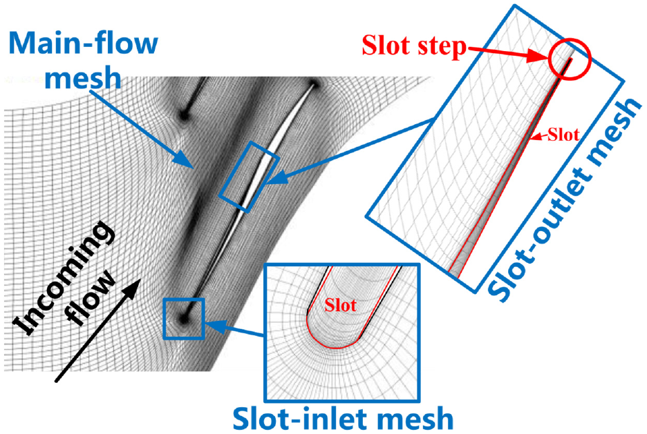
S1 surface mesh.
Assessing the influence of different span slotting on the aerodynamic performance of the rotor
First, blade slotting was conducted for full and partial spans to investigate the influence of slotting on the flow field in the rotor passage and its impact on the aerodynamic performance of the rotor.
Slotting for full span
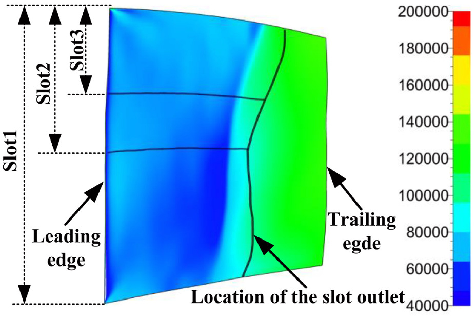
This section investigates the impact of a full-span slot on the aerodynamic performance of the rotor, and the slot parameters for typical blade spans are set as shown in Table 2. Due to the rapid development of the boundary layer starting at the intersection of the shock wave and the suction side, the slot outlet position is set near the downstream of the shock wave at each blade span, and the location of the slot relative to the blade is shown in Figure 9.
Slot parameters.


Static pressure (Pa) contour on the suction surface and the location of the slot outlet.
Figure 10 shows the design speed characteristics of the initial rotor and slotted rotor. The initial rotor is marked as Rotor37; the slotted rotor is marked as Slot1. Figure 10 and Table 3 show that compared with Rotor37, the mass flow rate at the choke point and peak efficiency point of Slot1 increased, while the total pressure ratio remained basically unchanged, and the isentropic efficiency significantly improved (1.8%). The stall margin (using the peak efficiency point as the design point) was increased by 4%. The jet flow rate in the slot is 1.08% of the total flow rate.

Comparison of rotor characteristics before and after slotting.
Performance at the peak efficiency point before and after slotting.

Figure 11 shows the radial distribution of the isentropic efficiency and total pressure ratio at the peak efficiency points of the two rotors. After slotting, the efficiency of the rotor is improved above 20% of the blade span, and the maximum efficiency improvement is achieved at 87% of the blade span, but the efficiency significantly decreases below 20% of the blade span; the total pressure ratio increases at the blade tip and decreases at the blade root, thus keeping the total pressure ratio of the rotor basically unchanged.

Radial distribution of typical parameters at the peak efficiency point before and after slotting: (a) isentropic efficiency and (b) total pressure ratio.
Figure 12 shows the relative Mach number contours of the S1 surface for 10%, 50%, and 90% spans at the peak efficiency point of Rotor37 and Slot1. Figure 13 shows the entropy contours of the corresponding S1 surface. Comparing Figure 12(b), (e), (c), and (f), at 50% and 90% spans, blade slotting reduces the size of the detached shock wave at the leading edge; the high-momentum fluid from the outlet of the slot is injected into the boundary layer of the suction surface, causing the upstream shock wave to move toward the downstream slot outlet position (see Figure 14), and the passage shock wave changes from a normal shock wave to a λ-type shock wave. The shock wave intensity weakens in the potential flow region near the pressure surface due to the wave, but the shock wave near the suction surface strengthens. Therefore, by comparing Figure 13(b), (e), (c), and (f), it can be seen that the entropy near the suction/pressure surface of the leading edge of the slotted blade decreases, while the entropy in the potential flow area near the pressure surface decreases; near the suction surface, due to the increase in shock wave intensity, the losses caused by the shock wave itself and its interaction with the boundary layer increase; however, the high momentum fluid injected by the jet suppresses the development of the boundary layer. Under the mutual cancellation effect of the last two factors, the boundary layer of the suction surface at 50% blade span thickens, and the losses and entropy on the suction surface side of the wake region increase (see Figure 15(b)); the boundary layer of the suction surface at 90% blade span becomes thinner, and the loss and entropy on the suction surface side of the wake region decrease (see Figure 15(c)). The boundary layer of the suction surface at 90% blade span is reduced, and the loss and entropy on the suction surface side of the wake region decrease (see Figure 12(c)).

Relative Mach number contours of S1 surface near slot outlet at 10%, 50%, and 90% blade spans: (a) Rotor37, 10% span, (b) Rotor37, 50% span, (c) Rotor37, 90% span, (d) Slot1, 10% span, (e) Slot1, 50% span, and (f) Slot1, 90% span.

Entropy contours of the S1 surface at 10%, 50%, and 90% blade spans: (a) Rotor37, 10% span, (b) Rotor37, 50% span, (c) Rotor37, 90% span, (d) Slot1, 10% span, (e) Slot1, 50% span, and (f) Slot1, 90% span.

Distribution of static pressure along the chord at 10%, 50%, and 90% blade spans: (a) 10% span, (b) 50% span, and (c) 90% span.

Tangential distribution of entropy in the wake area at 10%, 50%, and 90% blade spans: (a) 10% span, (b) 50% span, and (c) 90% span.
Figure 16 shows the limit streamlines of the two rotor suction surfaces at the peak efficiency point. This indicates that Rotor37 has a large range of radial migration of the boundary layer in the rear half of the blade, and low momentum fluid at the blade root is transported radially upward, reducing losses near the blade root. The slotting jet effectively suppresses radial migration of the boundary layer and recirculation region and instead causes an increase in losses near the blade root. Therefore, the efficiency near the root of the slotted rotor blade decreases (see Figure 11(a)), and the entropy of the suction surface in the wake region increases (see Figure 15(a)).

Limit streamline of suction surface: (a) Rotor37 and (b) Slot1.
Slotting for partial span
The rotor blade has a strong centrifugal force due to rotation, and the centrifugal force at the blade root is much greater than that at the blade tip. Therefore, slotting at the blade root has a greater impact on the blade structural strength than slotting at the blade tip, making slotting near the blade tip easier for engineering applications. This section investigates the effect of slotting near the blade tip on the aerodynamic performance of the rotor. The spans of the slot are shown in Table 4 (see Figure 17), and other slot parameters are the same as those in Table 2.
Slot parameters for slots with different blade spans.

Static pressure (Pa) contour on the suction surface and the location of the slot outlet for slots with different blade spans.
Figure 18 shows the design speed characteristics of Rotor37 and three slotted rotors. In Figure 18 and Table 5, it can be seen that compared with Rotor37, as the slot span decreases, the increase in peak efficiency decreases, the stall margin also slightly decreases, and the total pressure ratio remains almost unchanged. In Figure 19(a), it can be seen that slotting can increase the isentropic efficiency of the corresponding blade span, but the increase in isentropic efficiency decreases with increasing R1. The isentropic efficiency decreases to different degrees near the span of R1. Figure 20 shows that although Slot1, Slot2, and Slot3 have the same slots at 90% of the blade span, the flow field structures are different due to different slot spans, such as significant differences in the Mach number before the shock wave near the suction surface. Figure 21 shows that with different slot spans, the shock wave positions at 90% of the blade span are also different, and the shock wave positions with the full blade span slot are at the most downstream position. Figure 22 shows that with different slot spans, there are significant differences in the limit streamlines of the suction surface in the slotting area. The above results indicate that the flows of different blade spans affect each other, and the optimal slot structure is also different due to different blade slot spans.

Comparison of rotor characteristics for slots with different blade spans.
Performance at the peak efficiency point for slots with different blade spans.

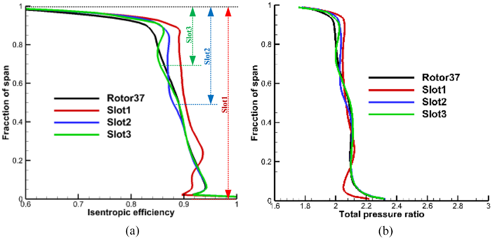
Radial distribution of typical parameters at the peak efficiency point for slots with different blade spans: (a) isentropic efficiency and (b) total pressure ratio.

Relative Mach number contours of the S1 surface near the slot outlet at a 90% blade span: (a) Rotor37, (b) Slot1, (c) Slot2, and (d) Slot3.

Distribution of static pressure along the chord at 90% blade span.
Limit streamline of the suction surface for slots with different blade spans: (a) Rotor37, (b) Slot1, (c) Slot2, and (d) Slot3.
Coupling optimization design of the slot and blade
The previous slot design has a significant improvement in efficiency, but due to the slot parameters set based on experience, there is plenty of room for improvement. Due to the coupling between the flow inside the slot and the mainstream, automatic optimization methods are used to optimize the coupling design between the slot and the blade to determine the optimal slot parameters and blade shape, further improving rotor performance.
Introduction to the automatic optimization method
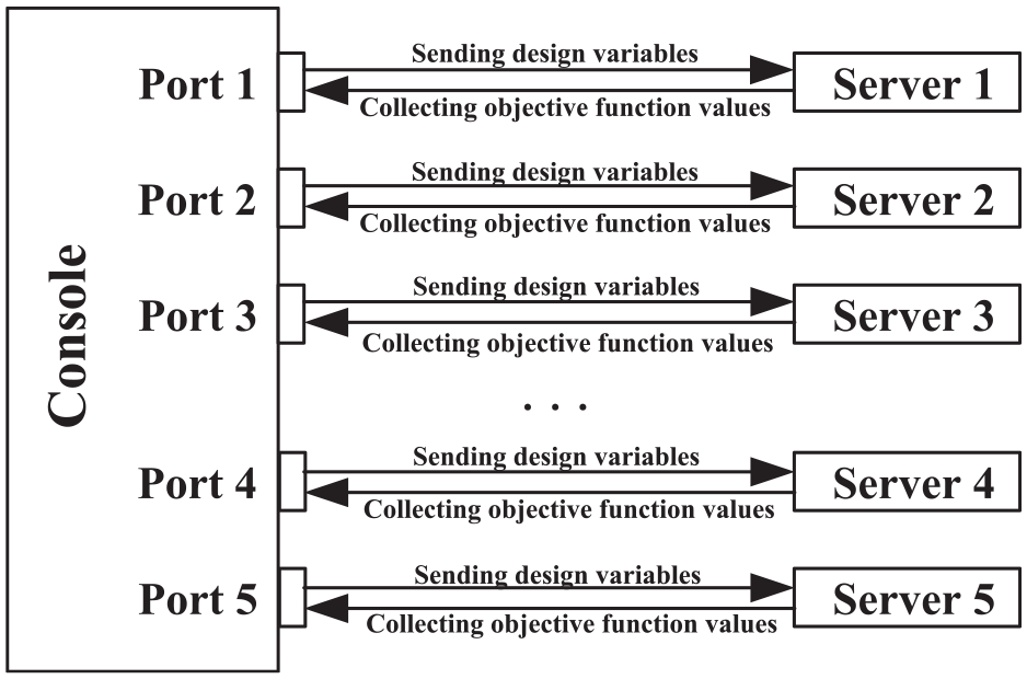
The automatic optimization method is based on existing optimization platform which is built by our research group based on genetic algorithm (GA). Based on the parallelism of GA, the optimization platform divides computer nodes of the local area network into console and server (seen in Figure 23). The console performs genetic algorithm evolution operations and sends design variables representing each individual to servers; The server converts the design variables into corresponding blade/slot geometry, calculates the flow field, calculates the values of each objective function, and returns the objective function values to the console. The optimal design is carried out on several compressor/fan rotors, stators and stages, and the results are satisfactory.26–28 The process of optimization is shown in Figure 24. The numerical optimization uses a GA; the initial blade superposition modification is used, and the modifications are obtained using the parameterization method of the Bezier curve
29
(seen in Figure 25). Only the blade profile and slot parameters are used as optimization design parameters. Due to the wide inlet setting of the slot, the flow rate inside the slot is determined by the outlet width, and the shape of the slot has a negligible impact on the mainstream flow field.
19
Therefore, the slot parameters only include the slot outlet position

The data communication process of parallel genetic algorithm.

The process of automatically optimizing the design.
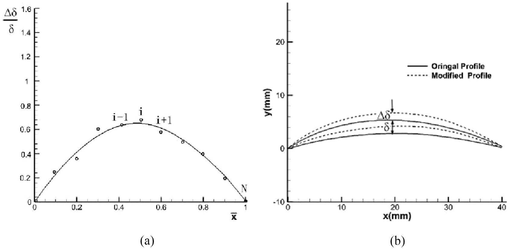
Sketch of the parameterization 29 : (a) modification curve and (b) original and modified profile.
Optimization parameter setting of the mean camber line.

The optimization objective function is given by equation (1):

where
Analysis of optimization results
Figures 26 and 27 show the positions of the slot outlet on the suction side of the blade before and after optimization, respectively, as well as the comparison of blade profiles before and after optimization for each optimized span.
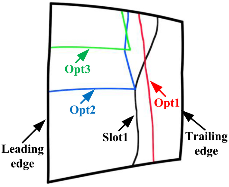
The relative position between the optimized slot outlet and the blade.

Blade profiles and slot geometries before and after optimization: (a) 0% span, (b) 25% span, (c) 50% span, (d) 75% span, and (e) 100% span.
Figure 28 shows the comparison of rotor characteristics before and after optimization. Combined with Table 7, it can be seen that the optimized slotted rotor Opt1–Opt3 has a significant improvement in isentropic efficiency compared to the corresponding original slotted rotor Slot1–Slot3. The changes in the total pressure ratio and stall margin are relatively small, and the jet flow rate in the slot has significantly increased. In Figure 29(a), it can be seen that within the span range of the slotted blades, the isentropic efficiency of the optimized slotted rotor Opt1–Opt3 is significantly higher than that of the corresponding original slotted rotor Slot1–Slot3; Figure 29(b) shows that the total pressure ratio of Opt1–Opt3 remains basically unchanged after optimization (this is one of the optimization objectives).

Rotor characteristics before and after optimization: (a) isentropic efficiency and (b) total pressure ratio.
Performance at the peak efficiency point before and after optimization.


Radial distribution of typical parameters at the peak efficiency point of slotted rotors before and after optimization: (a) isentropic efficiency and (b) total pressure ratio.
Figure 30 shows the Mach number contours of the 90% blade span of the original and optimized slotted rotor. It can be seen in Figure 30 that the passage shock wave of the original slotted rotor Slot1 is strong near the suction surface, while the shock wave of the optimized rotor Opt1 is significantly weaker. However, the passage shock waves of the original slotted rotors Slot2 and Slot3 are relatively weak, and there is little change after optimization. Figure 31 shows the static pressure contours of the suction surface of the optimized rotor blade, which can indicate the location of the shock wave, and the location of the slot is marked in the figure. Figure 31(a)–(c) show that for the three optimized rotors Opt1, Opt2, and Opt3, in the tip region with strong shockwaves, the slot outlets are near and upstream of the shockwave. As shown in Figure 31(a) and (b), in the middle and root regions with weaker shockwaves, the slot outlets are located downstream of the shockwave, and the further toward the root, the farther away the slot outlets are from the shockwave. Figure 32 shows that all three slotted rotors can significantly reduce the flow loss on the suction surface after optimization.

Relative Mach number contours of the S1 surface near the slot outlet at a 90% span before and after optimization: (a) Slot1, (b) Slot2, (c) Slot3, (d) Opt1, (e) Opt2, and (f) Opt3.

Static pressure (Pa) contours of the suction surface of optimized rotors and the position of the inlet and outlet of the slots: (a) Opt1, (b) Opt2, and (c) Opt3.

Tangential distribution of entropy in the wake area at 90% span before and after optimization.
Conclusions
This paper adopts an internal blade slot design to improve the rotor efficiency and stall margin of a supersonic compressor rotor. The slot inlet is located at the leading edge of the blade, and the outlet is located on the suction surface. By utilizing the high-speed air at the rotor inlet, a high-momentum microjet is formed at the slot outlet of the blade suction surface, which effectively suppresses the development of the boundary layer on the suction surface. The following conclusions can be drawn.
(1) Adopting this slotting method can effectively suppress the development of the boundary layer on the suction surface of supersonic rotor blades and at the same time move the position of the passage shock wave incident on the boundary layer of the suction surface toward the downstream near slot outlet, thereby reducing the shock wave intensity and shock wave loss, effectively improving the peak efficiency and stall margin of the rotor. The larger the range of the slot along the blade span is, the better the improvement effect.
(2) The coupling optimization design of slotted blades using the blade shape and slot parameters as optimization parameters shows that due to the strong shock wave in the passage near the blade tip, the local slot outlet should be near and upstream of the shock wave; for the middle and root regions of the blade, the shock wave is weak, and the local slot outlet should be located downstream of the shock wave.
Footnotes
Appendix
Handling Editor: Chenhui Liang
Declaration of Conflicting Interests
The author(s) declared no potential conflicts of interest with respect to the research, authorship, and/or publication of this article.
Funding
The author(s) disclosed receipt of the following financial support for the research, authorship, and/or publication of this article: This work was supported by the National Science and Technology Major Project (2017-II-0001-0013).