
Abstract
This study focuses on a novel clutchless and synchronizer-free drive system designed explicitly for pure electric vehicles. In contrast to the majority of previous research that solely considers internal excitations, this study not only incorporates various non-linear factors such as time-varying friction forces, time-varying mesh stiffness, and damping associated with internal excitations but also places significant emphasis on analyzing the impact of non-linear external excitations, including road surface unevenness and motor torque fluctuations, on the shifting process of the drive system. Subsequently, a non-linear dynamic model of the shifting process is established. In the modeling process, departing from the traditional two-degree-of-freedom quarter vehicle dynamics model, this study adopts an elastic tire-body and elastic tire-tread tire model, enabling the establishment of a highly accurate multi-degree-of-freedom quarter vehicle dynamics model. The simulation results indicate that road surface roughness and motor torque fluctuation significantly impact the gear-shifting process and the impact of road surface roughness increases with the level of roughness. Moreover, the effect of motor torque fluctuation on the gear-shifting process varies depending on different factors and is not simply additive. Consequently, when formulating and optimizing shifting strategies, it becomes imperative to consider various external factors. The research methodology integrates these factors into the dynamic analysis of the shifting process, providing a theoretical basis for developing effective shifting control strategies while considering external excitations.
Introduction
With the continuous development of new energy vehicle industry, in addition to the scheme of motor plus single-stage transmission in the transmission system of pure electric vehicle, the scheme of motor plus multi-speed transmission is gradually increasing and has become a trend. The use of a motor and multi-speed transmission can ensure that the vehicle operates in the high-efficiency range of the motor more than 90% of the time, reducing energy consumption and increasing the driving range. In particular, the use of a two-speed transmission can significantly increase the driving range of the vehicle, with the theoretical analysis showing that the motor efficiency can be improved by 4%–15%.1–4 Due to the high efficiency of gear transmission, multi-speed shifting systems often use this form. At the same time, due to the advantages of high efficiency, low cost, and simple structure of electric drive mechanical transmissions, and the application and development of motor technology and motor control technology in new energy vehicles, a new type of transmission without synchronizers or clutches has gradually been applied.5,6 Due to the emergence of the scheme of motor plus multi-shift transmission, it is essential to consider the dynamic characteristics and influencing factors of transmission system shift process when analyzing the shift quality of pure electric vehicle.
At present, many scholars pay more attention to the influence of internal excitation on transmission system, such as time-varying meshing stiffness, meshing damping, tooth clearance, and so on.7–10 Literature 7 established a dynamic model of the planetary gear system, taking into account the influence of time-varying meshing stiffness. The analysis results show that the time-varying meshing stiffness significantly affects the high-order natural frequency, and the high-order natural frequency of the contact point changes drastically, which is related to the meshing phase difference closely. Liu et al. 8 analyzes the influence of the clearance on the transmission system in the multi-gear transmission. The results show that the meshing clearance has an obvious influence on the nonlinear characteristics of the gear system, affecting the amplitude of the primary resonance, the overlap width of the jump frequency, and the degree of chaos. The nonlinear dynamic model of bevel gear pair considering time-varying meshing stiffness, transmission error and tooth clearance is established in reference 9, and the influence of meshing stiffness asymmetry on the vibration of bevel gear transmission system is studied emphatically. The results show that the meshing stiffness of the driving side has a great influence on the dynamic response, and the change of the meshing stiffness of the driving side will affect the corresponding in the whole range of excitation frequency. In addition, the increase of meshing stiffness of the driving side will aggravate the vibration of the transmission system, especially in the case of light load. Elmaksoud et al. 10 analyzes the influence of damping and friction coefficient on the dynamic behavior and stability of the automatic transmission system. The fluctuation of the transmission process is mainly caused by the excitation caused by friction elements, and the increase of damping value will often restrain the vibration of the system and improve the stability of the system.
At the same time, the early research on the contact surface friction force of the shift transmission system mostly assumes that the contact surface friction coefficient is uniform, but the actual experimental results show that the tooth surface friction coefficient of the transmission system varies periodically. In the later stage, the researchers use specific empirical formulas to get the friction coefficient, but these empirical formulas have some limitations, which are usually required to be more accurate under certain conditions. 11 As for the external excitation, such as road roughness factor, torque fluctuation of driving motor, and so on, most studies focus on the dynamic characteristics of the vehicle in the steady driving state.12–14 The influence of road roughness on vehicle vibration is analyzed in references 12 and 13. The results show that the vehicle vibration intensity increases geometrically with the increase of road roughness, and the vibration increases with the increase of vehicle speed. However, there will be a gentle range when the vibration intensity increases to a certain extent. The influence of torque fluctuation on vehicle dynamics is analyzed in reference 14. The influence of torque fluctuation of driving motor on vehicle dynamics is mainly reflected in the influence on vehicle driving force, which will reduce the ride comfort of vehicle.
The shifting process of the transmission system is a relatively frequent action during driving, and the smoothness of the shifting directly affects the driving quality of the vehicle. Therefore, it is necessary to focus on research and analysis of the impact of external excitations on the dynamic characteristics of the shifting process. In order to improve the shift quality of pure electric vehicle and optimize the dynamic characteristics of the shift process, this article takes the two-speed gear-shifting system without synchronizers or clutches as the research object. In addition to considering non-linear factors such as time-varying mesh stiffness, mesh damping, and tooth side clearance, this study differs from most studies by establishing a non-linear dynamic model of the shifting process that includes time-varying friction coefficients.15,16 Then conducts a comprehensive analysis of the effects of external stimuli such as motor torque fluctuations and road roughness on the shifting process. This analysis method provides a theoretical reference for improving the driving quality of pure electric vehicles and optimizing the shift control strategy.
Parameter identification
The schematic diagram of a two-speed clutchless and synchronizerless transmission system is shown in Figure 1. In the transmission system, the power coupling component consists of a sliding sleeve and an engagement gear, and the gear shifting is achieved by changing the position of the sliding sleeve. The shifting process can be divided into five stages: unloading of the motor torque, disengagement of the gear, synchronization of the motor speed, engagement of the gear, and recovery of the motor torque.
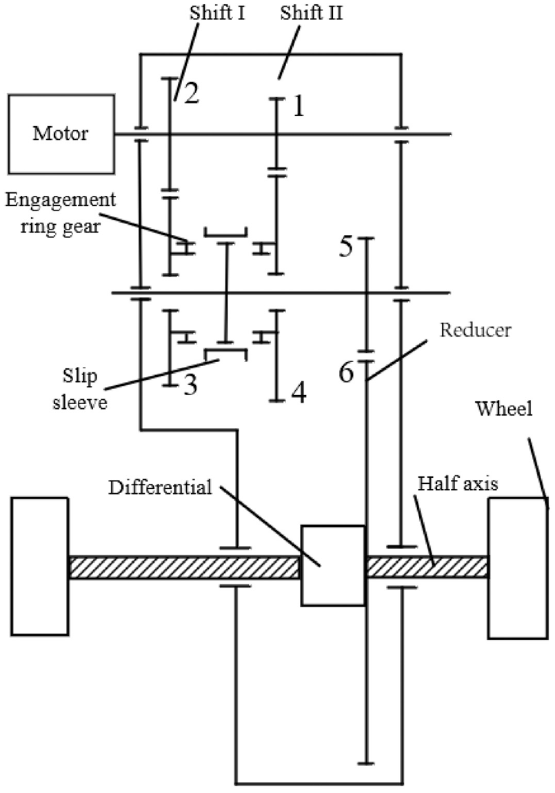
Schematic diagram of two-speed shift system.
Time-varying coefficient of friction
During the engagement process, the magnitude and direction of the friction force between the two tooth surfaces vary with the change in the engagement position, creating a non-harmonic internal excitation within the gear transmission system. The schematic diagram of the engagement process is shown in Figure 2.
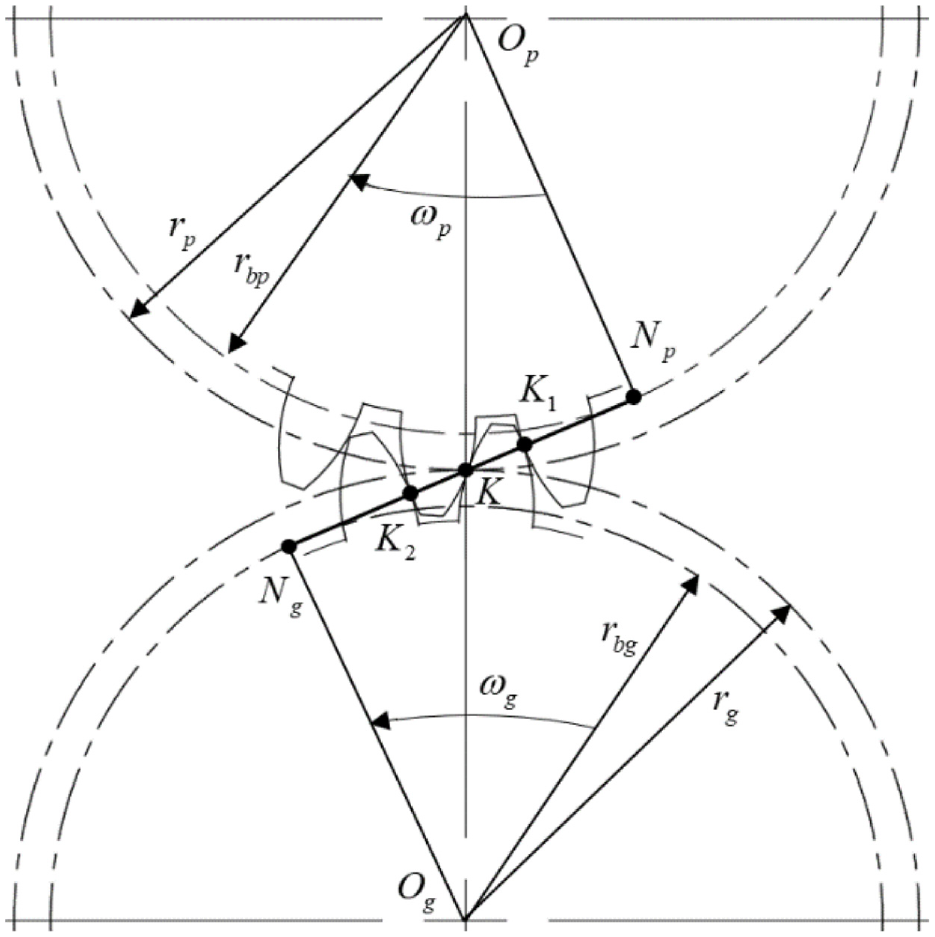
Schematic diagram of gear meshing.
The non-Newtonian thermoelastic lubrication theory was applied by Xu et al.17,18 to predict the friction coefficient distribution of all contact points in gear meshing, and a formula for variable friction coefficient was derived. They compared the predicted values of the friction model with the efficiency measurement values of various gear designs and surface-treated gear pairs, and the results demonstrated that the proposed new friction coefficient formula was accurate and widely applicable. However, at extremely low speeds such as 0.001 r/min, the mean friction coefficient of this variable formula is greater than 0.2, which exceeds the numerical range of the boundary friction coefficient (0.1–0.15). 19 The reason for this is that the formula is obtained by multi-parameter fitting, and the fitting speed is not low enough, leading to a large prediction error of the friction coefficient at low speeds. When the speed is greater than 0.1 r/min, the predicted value under mixed lubrication is very close to the actual situation. Since this article aims to focus on analyzing the dynamic characteristics of time-varying friction during the shifting process, there is no situation where the rotation speed of the meshing gear is zero or the rotation speed is less than 0.001 r/min, so it is fully consistent with the application of this friction coefficient calculation formula range. Therefore this article adopts the friction coefficient calculation formula and its expression for the friction coefficient is shown below


Where


Here
The friction factor
Here
Time-varying mesh stiffness and damping
The main methods to obtain gear time-varying meshing stiffness are analytical method, finite element method, experimental method, and so on. The time consumed by finite element method is generally longer than other methods, but it is usually the most real and accurate result. 20 Therefore, this paper uses the finite element software to simulate and calculate the model of a single pair of helical gears. Taking the meshing stiffness of the first gear pair as an example, the simulation results are as follows (Figure 3):

Mesh stiffness curve.
As can be seen from the figure, the mesh stiffness curve of gears exhibits periodic variation with gear rotation and can be represented as a Fourier series

The average mesh stiffness is denoted by

Empirical formulas are commonly used to calculate the mesh damping, which can be expressed as follows

Here,
Tooth backlash and static mesh error
When designing and assembling gears, it is important to ensure that a certain amount of clearance is maintained between teeth to allow for the formation of a lubricating film between the tooth surfaces. However, excessive tooth clearance can also lead to gear impact and vibration. The function of tooth clearance can be expressed as follows

In the equation, b represents half of the backlash, and x represents the system’s torsional displacement. The physical interpretation of the tooth side clearance function is as follows: when x > b, the gear enters meshing; when −b < x < b, the gear is in disengagement; and when x < −b, the gear experiences tooth flank collision.
During the process of manufacturing gears, tooth profile errors may occur, and during the assembly process, there may be positional errors, which are collectively referred to as static errors

Here, e represents the magnitude of the static error, and its empirical value is typically taken as
Nonlinear dynamic model for gear shifting processs
The diagram in Figure 4 shows the nonlinear torsional model for a two-gear transmission system that does not have a synchronizer or clutch. The solid wireframe represents the coupling position, while the dotted wireframe represents the uncoupling position of the sleeve. The input and intermediate shafts of the gearbox are shorter and stiffer than the half shafts and tires of the transmission system. Thus, the model can be represented by a seven-degree-of-freedom nonlinear torsional vibration model if the torsional stiffness of the gearbox shaft is not considered. The diagram,

Schematic diagram of a nonlinear torsional model of the transmission system.
By taking into account nonlinear factors such as meshing stiffness, meshing damping, tooth clearance, and static error of helical gear pairs in the gearbox, the dynamic meshing errors

where
Here


where b represents the tooth clearance and
Based on the schematic of the nonlinear torsion model shown in Figure 4, and taking into account the variable friction force during gear meshing, the nonlinear dynamic equations for both the coupled and decoupled states of each component during the shifting process can be expressed as follows


Here,
External excitation
Torsional excitation of gear shifting process due to road surface roughness
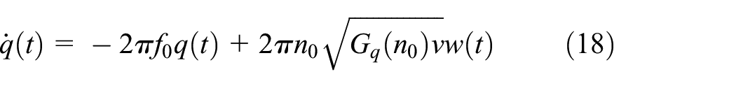
The power spectral density function of the road surface displacement q in the time domain can be expressed by integrating over time, as follows 22

Here,
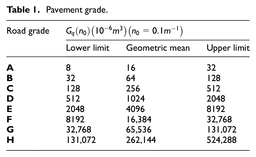
After conducting a simulation analysis to determine the parameters, 23 the time-domain model of road roughness can be represented as follows

The parameter
Pavement grade.
As shown in Figure 5, a vehicle multi-degree-of-freedom model is constructed. To achieve a closer representation of real-world conditions, this model deviates from the conventional two-degree-of-freedom quarter vehicle model. Instead, it integrates the elastic tire-body and elastic tire-tread tire model.
24
The tire is divided into two distinct components: the elastic hub and rim. Furthermore, the model takes into account the unevenness of the road surface. This approach results in the establishment of a quarter vehicle model with multiple degrees of freedom, enhancing its accuracy and realism.

1/4 vehicle multi-degree of freedom model.
When a car is driven on an uneven road surface, the vertical vibrations of the car cause the vertical forces between the driving wheels and the road surface to constantly change. Consequently, the wheel radius changes accordingly, leading to a change in the driving torque


The model shows that the tangential force

Where
When discussing the case of a car driving on a hard road surface, the formula for
When
The time for a vehicle to shift gears is very short, and the vehicle’s speed does not change much during this time, which can be approximately considered as running at a constant speed. Thus, the driving resistance torque experienced by the vehicle running at a constant speed on a hard road surface can be expressed as follows

Where
Model of driving motor torque fluctuations
Harmonic torque ripple of magnetic flux
The electromagnetic torque output by the motor can be expressed as 25

Where


After expansion, we get

Let
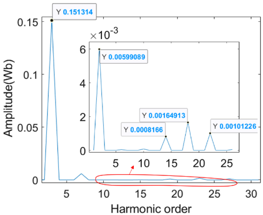
The motor used in this paper is an 8-pole 48-slot permanent magnet synchronous motor with a rated power of 100 kW and a rated torque of 100 Nm. ANSYS Electronics finite element software is employed for motor simulation. The direct impact of the harmonic of the permanent magnet excitation magnetic field on torque fluctuation is mainly reflected in the permanent magnet flux, so the harmonic situation of the permanent magnet flux is analyzed by simulation. Figure 6 shows the magnetic flux distribution of the A, B, and C phase windings obtained from the simulation. Taking the A phase as an example, the harmonic content of the magnetic flux is expanded using the Fourier series, as shown in Figure 6. Some of the larger numerical values are shown in Table 2.
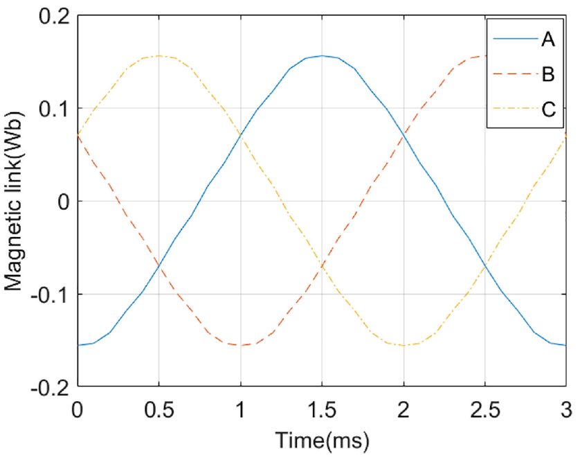
Flux linkage diagram of three-phase winding.
FFT expanded partial harmonic components.

Based on the data in Figure 7 and Table 2, it can be inferred that, in general, the higher the harmonic order, the smaller the overall magnetic flux amplitude. By expanding the Fourier series, the expression of the permanent magnet flux can be represented as

For the convenience of calculation, only the magnetic flux parameters with larger values in the first few terms are considered. Substituting these parameters into the permanent magnet flux expression containing harmonic components can be represented as follows:

Therefore, according to the expression of torque ripple, the torque ripple component caused by the harmonic of the permanent magnet flux linkage can be approximately expressed as:

Here
Flux linkage harmonic FFT expansion.
Magnetic slot torque ripple
The no-load cogging torque of a permanent magnet synchronous motor was simulated and calculated using ANSYS Electronics finite element software, and the simulation results are shown in Figure 8. Based on the Fourier series expansion, the harmonic cogging torque waveform is shown in Figure 9.

No-load cogging torque fluctuation.
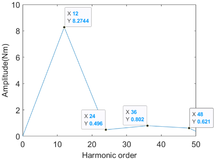
No-load cogging torque harmonic diagram.
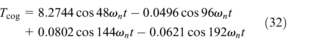
Since a permanent magnet synchronous motor with 8 poles and 48 slots is employed, the minimum number of cogging torque harmonics is 48 times the mechanical angular frequency or 12 times the electrical angular frequency. As the harmonic order increases, the amplitude of the overall harmonic decreases. In order to simplify the calculation, only the harmonic parameters of the first four orders are considered. Thus, the cogging torque can be expressed as follows:
By substituting the expressions for torque fluctuation
Simulation analysis
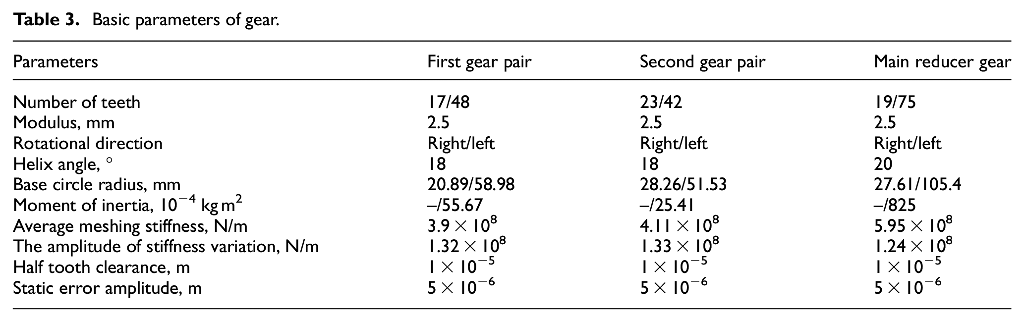
A nonlinear dynamic model of the shifting process was constructed using MATLAB/Simulink, and the simulation parameters are shown in Tables 3 and 4.
Basic parameters of gear.
Powertrain parameters.

Effects of road surface roughness excitation on gear shift process
Comparison and analysis of the effect of road surface roughness excitation on the vibration shock of the shifting process in the nonlinear dynamic model are shown in Figures 10 and 11. For a more intuitive comparison, the simulation data (blue) was fitted and represented by the red curve in the figures. It can be observed from the shifting process of the transmission that the shock mainly occurs during the gear disengagement and gear engagement stages. During gear disengagement, there is a sudden change in the moment of inertia, resulting in a sudden increase in shock. During gear engagement, shock occurs due to the change in moment of inertia as well as the collision between the synchromesh and the engagement teeth.

Without considering road roughness excitation.

Considering road roughness excitation.
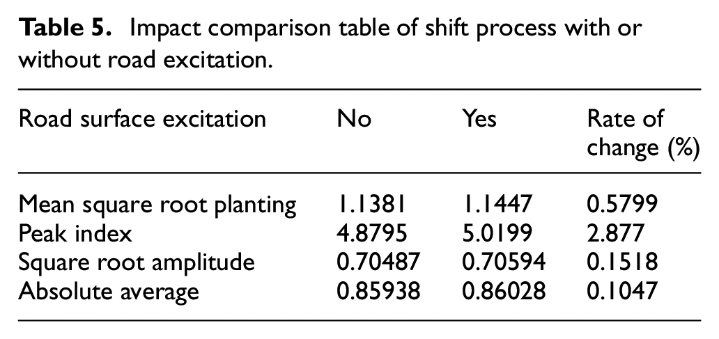
Commonly used evaluation indicators for impact vibration signals include root mean square (RMS) value, root amplitude, the maximum value or maximum absolute value (peak), and other indicators. Among these, the RMS value, also known as the effective value, is the indicator that engineers are typically most concerned about, as it reflects the energy intensity and stability of the vibration signal. Meanwhile, the peak value indicator is typically used to detect the presence of impacts in the signal. Table 5 shows the specific vibration impact parameter indicators. When considering the influence of road roughness, the shifting process exhibits significant and severe fluctuations, with the impact degree peak value increasing during the unloading and gear engagement stages. The important indicator of impact vibration signal, the RMS value, increased by 0.5799%, the peak value increased by 2.877%, the root amplitude increased by 0.1518%, and the absolute average value increased by 0.1047%. This further illustrates that road surface roughness excitation increases the impact during the shifting process.
Impact comparison table of shift process with or without road excitation.
The influence of different road surface levels on the shifting process
The simulation was conducted for different road grades: A, B, C, and D. The vibration impact diagram of the shifting process in Figure 12 and the vibration evaluation index in Table 6 reveal that road excitation will increase the impact of the vehicle, and this effect will intensify as road roughness increases. As illustrated in Figure 13, the influence of road grades A and B on the impact of the shifting process is relatively minor, while the influence of road grades C and D significantly increases as road roughness continues to escalate. Therefore, in formulating shifting control strategies, it is essential to consider road roughness as a reference factor in addition to traditional factors such as vehicle speed, acceleration, and throttle opening. Different shifting strategies can be formulated on different roads. For instance, for the non-synchronous and non-clutch shifting systems studied in this paper, it would be possible to select a smaller allowable shifting speed difference as road roughness increases. This would help reduce the impact of the shifting process and even enhance the smoothness of vehicle driving.

Influence of different road grades on shift process: (a) road grade A, (b) road grade B, (c) road grade C, and (d) road grade D.
Vibration parameter indexes of different road grades to shift process.


Schematic diagram of vibration index for shift process of different pavement grades.
Effect of torque fluctuation on the shifting process
Both the torque ripple caused by the teeth slot and the excitation magnetic field harmonics of the permanent magnet is introduced into the nonlinear shift dynamic equation simultaneously. The simulation result is shown in Figure 14:

Comparison diagram of impact degree in the shifting process: (a) without considering motor torque fluctuation, (b) considering the factor of magnetic slot, (c) considering the harmonic factor of the magnetic field, and (d) considering the harmonic factors of cogging and magnetic field.
By comparing the impact force diagrams of various shifting conditions, and focusing on the key moment of the shifting process, which is the gear engagement phase, it can be observed that the peak impact force during the gear engagement phase is increased when considering the nonlinear dynamic model with the torque ripple excitation. The specific numerical values are shown in Table 7.
Table of peak impact during gear shifting.
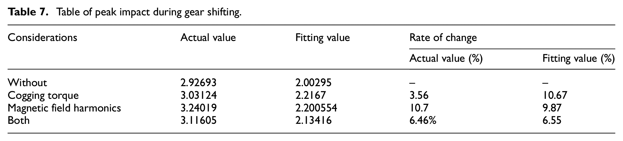
By examining the results in Table 7, it is evident that torque ripple excitation amplifies the impact of the shifting process. The peak value of the impact during the gear engagement phase increases by 3.56%, 10.7%, and 6.46% when considering separately the torque ripple caused by the slot and the permanent magnet excitation magnetic field harmonic, and when considering both factors simultaneously. The corresponding fitting values show an increase in peak impact of 10.67%, 9.87%, and 6.55%, respectively. It is found that when considering the impact of both factors causing torque ripple on the shifting process, their change rates are smaller than when considering only the impact of the torque ripple caused by the permanent magnet excitation magnetic field harmonic. This indicates that the effects of the two factors may cancel each other out under certain conditions, and their impact on the shifting process is not simply additive. However, overall, it is concluded that motor torque ripple amplifies the impact of the shifting process, and based on simulation results, the increase in peak impact is approximately 6.5%. Therefore, to enhance the smoothness of the vehicle shifting process, it is imperative to suppress motor torque ripple.
Conclusion
(1) This article presents a study on a novel type of gear-shifting system that operates without a clutch or synchronizer. The study mainly investigates the effects of external factors such as road surface roughness and motor torque fluctuation. A dynamic model for the shifting process of the gear shifting system is established, taking into account nonlinear factors such as time-varying friction force, time-varying meshing stiffness, and damping.
(2) The impact of road roughness excitation on the shifting process was analyzed, and simulation results show that with the increase of road roughness level, the shock of the shifting process also increases accordingly. Therefore, when formulating shifting control strategies, road roughness should be considered as one of the factors in order to improve the smoothness of the shifting process.
(3) The impact of motor torque fluctuations on the shifting process was also analyzed in this study, with a focus on the torque fluctuations caused by magnetic field harmonics and magnetic slot torque. The simulation results showed that motor torque fluctuations exacerbate the impact of the shifting process. However, the influence of torque fluctuations caused by different factors on the shifting process is not simply additive, and further analysis is needed. Therefore, it is necessary to develop control strategies to suppress motor torque fluctuations, improve the smoothness of the shifting process, and even enhance the driving quality of the vehicle.
To summarize, external excitations such as road roughness and motor torque fluctuations exacerbate the shock impact of the gear-shifting process. Therefore, when applying gear-shifting systems, it is essential to conduct a detailed analysis of the impact of external excitations on the dynamic characteristics of the gear-shifting process. This analysis provides a theoretical reference for designing gear-shifting systems and formulating control strategies.
Footnotes
Appendix
Handling Editor: Chenhui Liang
Declaration of conflicting interests
The author(s) declared no potential conflicts of interest with respect to the research, authorship, and/or publication of this article.
Funding
The author(s) disclosed receipt of the following financial support for the research, authorship, and/or publication of this article: This work was supported by the National Nature Science Foundation of China [grant number 51575041].