
Abstract
Difficult-to-machine materials such as stainless steel are widely used in the construction industry, because of their excellent mechanical properties and corrosion resistance. However, the poor tool-chip contact environment, severe tool wear, and heavy chip accumulation inhibit the machining efficiency. In this paper, 316L austenitic stainless steel was selected to investigate the effect of a variable-length restricted contact tool (VL-RCT), aiming at reducing the cutting temperature and increasing the tool life. A finite element simulation model of restricted contact cutting was established to investigate the machining parameters and restricted contact parameters on cutting performances and to clarify the mechanism of the VL-RCT in the cutting process. Additionally, cutting experiments were conducted to verify the cutting process mechanism. The results showed that the variable restricted contact structure efficiently reduced the cutting force and cutting temperature and improved the cutting performances of austenitic stainless steel. Both numerical simulation and cutting experiments reported that the trapezoidal restricted contact structure improved the cutting performance the best. Accordingly, this research provided theoretical guidance for the optimization of tool structure and the selection of cutting parameters, as well as a solid foundation for the future development of relevant design theories and methods for high-performance tools.
Keywords
Introduction
With the rapid development of the construction industry, port shipbuilding, petrochemical industry, etc., the demand for stainless-steel materials in the manufacturing industry and engineering structures is increasing.1,2 And austenitic stainless steel has received widespread attention because of its excellent mechanical properties 3 and corrosion resistance.4,5 Nevertheless, in addition to high toughness and poor thermal conductivity, austenitic stainless steel exhibits severe work-hardening in the cutting process. As a difficult-to-machine material, 316L austenitic stainless steel produces large section shrinkage and cutting resistance during cutting at room temperature. Accordingly, severe work hardening and thermal-force loads impede its machining efficiency. 6 Such defects deteriorate the tool-chip contact interface and lead to severe tool wear.
Several methods exist to improve the machining performance of stainless steel. The first approach is to set up the lubrication environment, for example, eco-friendly vegetable oil-based cooling lubricants, 7 supercritical carbon dioxide cooling technology, 8 and minimal quantity lubrication.9,10 A cool and lubricated environment can reduce the cutting temperature and improve the quality of the machined surface. The second method is external auxiliary equipment, such as laser-assisted machining,11,12 electric pulse-assisted machining, 13 and jet-assisted high-speed machining. 14 They focus on changing the mechanical-mechanical properties of the workpiece material or inducing localized material phase transitions to improve the machinability of difficult-to-machine materials. Higher strength and hardness tool materials also result in longer tool life and satisfactory surface quality. For example, cubic boron nitride tools have high hardness and chemical inertness, 15 surface-coated tools exhibit superior mechanical properties, 16 and coated-steel matrix composites offer high strength and wear resistance. 17
Nevertheless, traditional lubricants may be harmful to the environment and humans, and new lubrication methods may be expensive or difficult to operate.18,19 Some novel tool materials or coating materials have low impact toughness and their research cycles are relatively long.20,21 Notably, spraying liquid nitrogen or gases during machining tends to form microcracks and cause stress corrosion expansion. 22 Based on the above facts, restricted contact tool (RCT) design is the future trend for green and efficient machining.
Through extensive experiments, Ortiz-de-Zarate et al. 23 successfully predicted friction and normal stress distribution on the rake face using partially restricted contact length tools. Jiang et al. 24 designed a restricted contact tool in the form of a microgroove, which could effectively improve the cutting performance. Through theoretical analysis, Arsecularatne 25 revealed that the restricted contact tool life increased as the rake tool face length decreased. Wang et al. 26 Probed that the restricted contact tool could effectively control chip curl and improve cutting accuracy using finite element simulation. The current studies mainly focus on the conventional tool (CT) and constant-length restricted contact tool (CL-RCT). The CL-RCT is essentially a rectangular restricted contact tool (R-RCT). However, there is a lack of research on the thermal-force characteristics, and the mechanism of the variable-length restricted contact tool (VL-RCT) during cutting.
To reduce the tool-chip interface temperature and increase the tool life, a novel design of VL-RCT was proposed. For the turning of difficult-to-machine materials, the finite element method was proven to be feasible and accurate. 27 Based on this, the simulation and experiment were combined to investigate the force-thermal characteristics and the mechanism of RCTs under different parameters. A comparative study of cutting 316L austenitic stainless steel using CL-RCT and VL-RCT was carried out. Parameters including cutting velocity (Vc), cutting thickness (t0), and restricted contact length (l) were investigated in depth. This study offered a guideline for tool structure optimization and parameter selection in cutting difficult-to-machine materials.
Materials and methods
Experimental setup
To investigate the cutting performances of different restricted contact structures, four RCTs were designed, as shown in Figure 1. The RCT was made on an uncoated carbide insert (YG 6) as a substrate, and the restricted contact structure was made by the wire-cut and micro EDM machining, and its error range was ±20 μm. Figure 1(a) to (d) were rectangular restricted contact tool (R-RCT), rectangular-trapezoidal restricted contact tool (RT-RCT), double trapezoidal restricted contact tool (DT-RCT), and trapezoidal restricted contact tool (T-RCT), respectively. The workpiece was an AISI 316L austenitic stainless steel round tube, whose detailed chemical composition and physical properties were shown in Table 1.

Different types of RCTs: (a) R-RCT, (b) RT-RCT, (c) DT-RCT, and (d) T-RCT.
The chemical composition, physical properties, and mechanical properties of AISI 316L austenitic stainless steel.

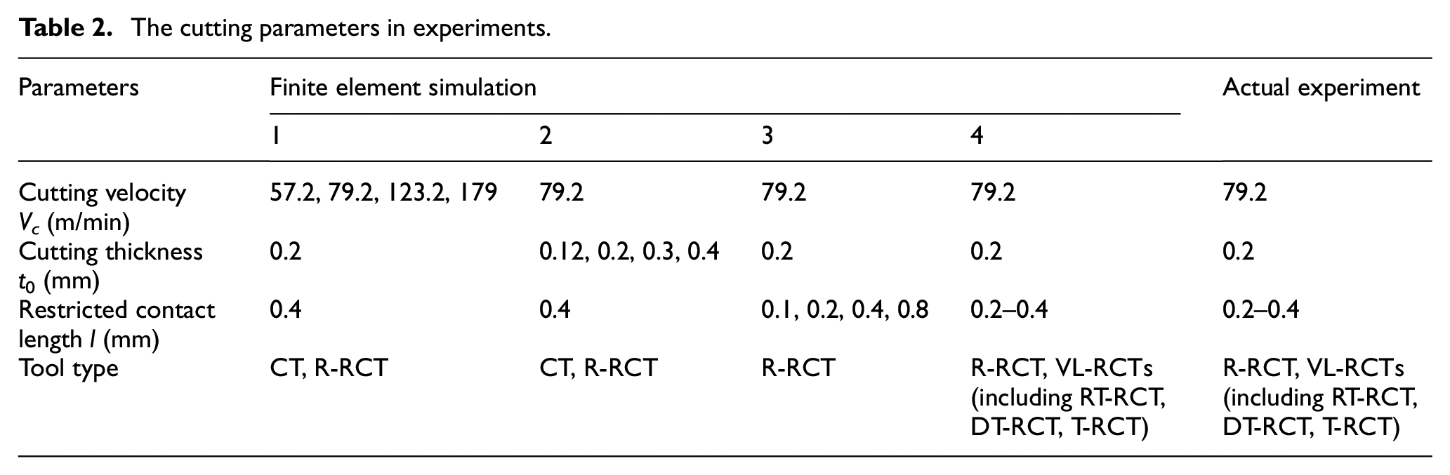
As illustrated in Figure 2, the cutting experiments were performed on a CA6140A lathe. The experimental parameters selected for the study are presented in Table 2. The value of cutting velocity was obtained by Vc = πd·n/1000, where d was the workpiece diameter (70 mm) and n was the lathe spindle rotational speed. The cutting thickness in this experiment was approximately equal to the feed, so the feed values of 0.12, 0.2, 0.3, and 0.4 on the lathe were chosen. The cutting temperature was measured by an infrared thermal imager (Fluke Ti-200, frame rate: 9 Hz, fps: 320 × 240 pixels, measurement accuracy: ±3°C). The cutting force was measured by a Kistler 9257A piezoelectric force gauge. Additionally, a Quanta 200 scanning electron microscope (SEM) was used to observe and analyze the tool wear. In the experiments, the ambient temperature was kept as consistent as possible, the devices were calibrated before force and temperature measurements, and three experiments were done for each set of parameters to rule out chance.

The experimental setup: (a) schematic diagram of the device connection and (b) diagram of the actual experiment.
The cutting parameters in experiments.
Finite element simulation modeling
To simplify the coordinate system and modeling process in the actual machining process, the rotary motion of the lathe was simplified to the tool’s linear motion relative to the workpiece. According to the simplified cutting process, the finite element simulation models of conventional cutting, constant-length restricted contact cutting, and variable restricted contact length cutting were established by using DEFORM-3D software, as shown in Figure 3.

Finite element model and meshing diagram: (a) CT, (b) CL-RCT, and (c) VL-RCT.
To ensure the accuracy of the results and improve the solution efficiency, the workpiece model was divided into 100,000 meshes. The meshes of the primary deformation area were further refined, where the minimum mesh size was 0.01 mm. The tool was set as a rigid body because of its much higher hardness than the workpiece material. The workpiece was set as a plastic body, and its J-C constitutive model expression is shown below 28 :

where A represents the yield stress, B represents the hardening coefficient, C represents the strain rate coefficient, n represents the hardening index, and ε represents the plastic strain.
J-C constitutive model parameters of AISI 316L austenitic stainless steel.

Due to the uneven distribution of the normal load on the rake tool face during the cutting process, a composite shear-Coulomb friction model was used to represent the friction between the rake tool face and the chip:

Where f is the friction force between the tool-chip contact interface. τs is the shear yield strength of the workpiece material. σn is the positive stress on the rake tool face, and μc is the Coulomb friction coefficient. To improve efficiency, the friction between the tool and the workpiece was simplified to Coulomb friction with a friction coefficient of 0.4.
Besides the conventional tool (CT), new restricted contact structures were designed based on the R-RCT. The finite element models of different types of RCTs were shown in Figure 4, and their geometric parameters were shown in Table 4.
Finite element models of different types of RCTs: (a) R-RCT, (b) RT-RCT, (c) DT-RCT, and (d) T-RCT.
The geometrical parameters of RCTs.

Results and discussion
Finite element simulation analysis
The effects of cutting parameters
Figure 5 showed the tool-chip contact of CT and R-RCT under different cutting parameters. For CT, the tool-chip contact length decreased as the Vc increased and the t0 decreased. As for R-RCT, the restricted contact length was the tool-chip contact length due to the restricted contact structure. For in-depth analysis, the detailed tool-chip contact lengths were shown in Figure 6. Compared with the CT, the tool-chip contact length was reduced the most when Vc was 57.2 m/min and t0 was 0.4 mm, by 48.19% and 59.56%, respectively.

Tool-chip contact of CT and R-RCT under different cutting velocities and cutting thicknesses.

Tool-chip contact length between CT and R-RCT under different (a) cutting velocity and (b) cutting thickness.
Figure 7 showed the main cutting force and feed force by CT and R-RCT under different cutting speeds and cutting thickness. For both CT and R-RCT, the cutting force components decreased with increasing Vc and increased with increasing t0. Whereas, the RCT reduced the cutting force components to a greater extent at small Vc and large t0. This is mainly because in this case, the restricted contact structure suppressed the tool-chip contact behavior significantly and thus reduced the cutting force.

The main cutting force and feed force by CT and R-RCT under different (a and b) cutting velocities and (c and d) cutting thicknesses.
To investigate the effect of different tools on the thermal characteristics during the cutting process, three fixed points p1, p2, and p3 were set at approximately one-half of t0 and 0.5 mm from the workpiece’s right side. The positions were shown in Figure 8, and the average temperatures of three points were taken as the temperatures.
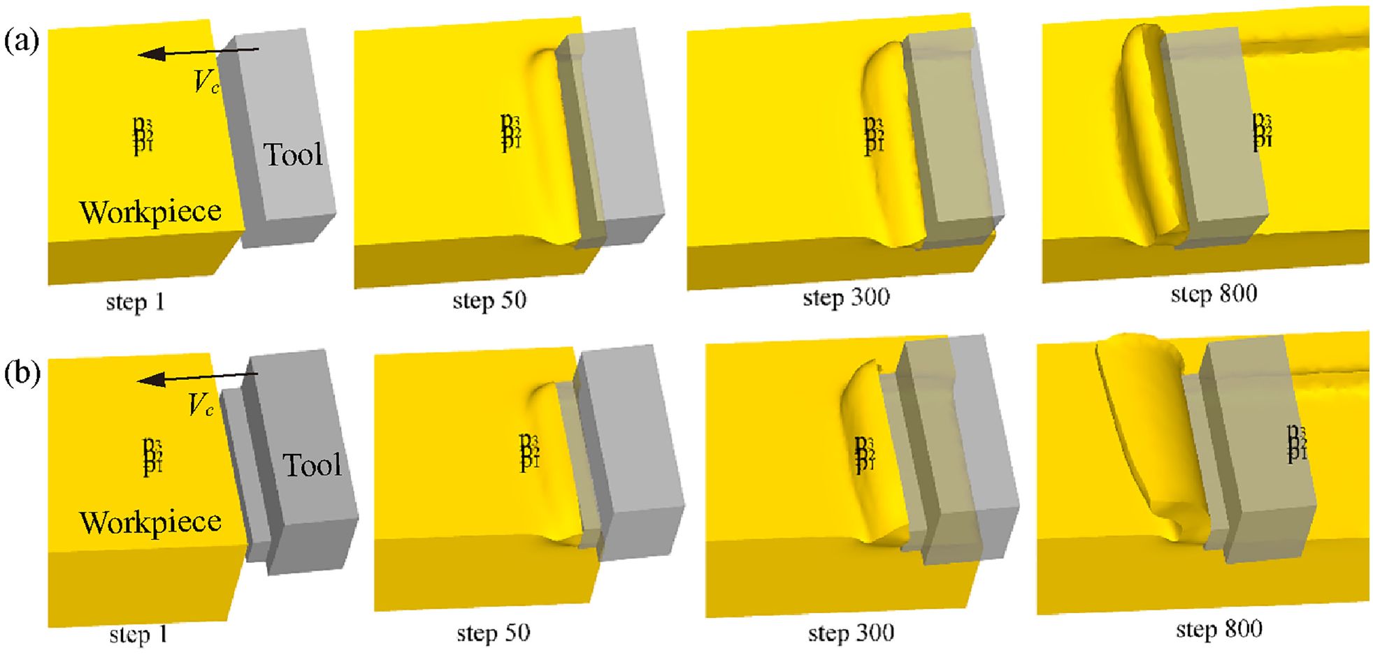
The position of fixed points in the cutting model under different steps: (a) CT and (b) R-RCT.
Figure 9 showed the cutting temperature distribution of CT and R-RCT under different cutting velocities and cutting thicknesses. With the increasing Vc and t0, the cutting temperature increased. At the same cutting speed and cutting thickness, the maximum temperature and the high-temperature range of R-RCT were smaller than that of CT, indicating that R-RCT could effectively reduce the cutting heat and lower the cutting temperature.

The cutting temperature distribution of CT and R-RCT under different cutting velocities and cutting thicknesses.
Figure 10 showed the temperature variation curves of the fixed points under different cutting parameters. The temperature underwent a rapid increase and a steady decrease.

The temperature variation curves of the fixed points under different cutting velocities and cutting thicknesses.
When cutting with R-RCT, the distance to the maximum temperature at the fixed point was shorter than that of CT. It was attributed to the location of the highest temperature point on the R-RCT rake face being closer to the cutting edge than CT, and the smaller the distance between the fixed point and the highest temperature point, the faster the temperature reached its maximum value. This phenomenon also indicated that the R-RCT structure was important for changing the high-temperature area.
The effects of restricted contact lengths l
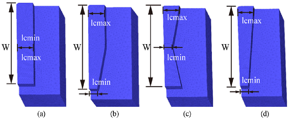
Figure 11 showed the effect of different restricted contact lengths on the tool-chip contact. When l < 0.4 mm, the tool-chip contact length was equal to the restricted contact length, indicating that the restricted contact structure directly inhibited the tool-chip contact and improved the cutting performance. By comparing the tool-chip contact length under different l, lc was 0.59 mm when l = 0.8 mm, implying that the tool failed to control the tool-chip contact. In this case, the impact of R-RCT on the machining process was the same as CT. Although the tool with a restricted contact structure was used, the cutting was still a conventional process.

Tool-chip contact of different restricted contact lengths l: (a) l = 0.1 mm, (b) l = 0.2 mm, (c) l = 0.4 mm, and (d) l = 0.8 mm.
Figure 12 showed the effect of different restricted contact lengths on the cutting force. As the l increased, the main cutting force and feed force increased. The cutting force was significantly reduced at l = 0.1 mm, with the main cutting force reduced by 32.7% and the feed force reduced by 37.24% compared to conventional cutting. The significant reduction in the cutting force was attributed to the reduction in the tool-chip contact area and the improvement in cutting performance.

The main cutting force and feed force by R-RCT under different restricted contact lengths l.
Figure 13 showed the cutting temperature distribution of R-RCT under different restricted contact lengths l. As the l decreases, the high-temperature area became smaller, indicating that shorter l also reduced the cutting heat generation. The temperature variation curves of R-RCT under different restricted contact lengths l were shown in Figure 14. The temperature variation supported the above results, revealing that the reduction of l also contributed to the machined surface temperature reduction.

The cutting temperature distribution of R-RCT under different restricted contact lengths l: (a) l = 0.1 mm, (b) l = 0.2 mm, (c) l = 0.4 mm, and (d) l = 0.8 mm.
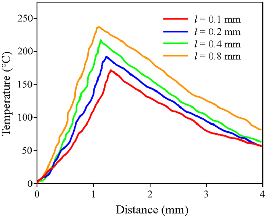
The temperature variation curves of the fixed points by R-RCT under different restricted contact lengths l.
To investigate the mechanism of CT and R-RCT in depth, a slip line model based on Merchant 29 shear slip theory was developed based on the finite element simulation results. The shear angle equation proposed by Merchant was as follows:

where β was the friction angle and γ0 was the tool rake angle. According to equation (3), the friction angle was inversely proportional to the shear angle when the rake angle was constant.
The shear angle in the cutting process under different l was illustrated in Figure 15, where t0 was the cutting thickness, tch was the chip thickness, and φ was the shear angle. When l = 0.8 mm, φ was the minimum, and the smaller the shear angle, the more significant the material deformation. Considering that the R-RCT did not act as a restricted contact when l was 0.8 mm in the previous analysis, the tool was equivalent to the CT. By comparing the shear angle of the CT (see Figure 15(d)) with other RCTs (see Figure 15(a)–(c)), it could be seen that CT showed worse cutting performance than RCT, which was supported by the results of Figure 12 where the cutting force of CT was larger than that of RCTs. Restricted contact cutting improved the tool-chip friction environment compared to normal cutting, contributing to the reduced cutting heat while reducing the friction angle and increasing the shear angle. It was also supported by the reducing high-temperature area with the decreasing l in Figure 13. Similarly, the φ increased as the l decreased in restricted contact cutting, indicating that reduced l could effectively improve the cutting performance.
The shear angle in the cutting process under different restricted contact lengths l: (a) l = 0.1 mm, (b) l = 0.2 mm, (c) l = 0.4 mm, and (d) l = 0.8 mm.
The effects of different RCT types
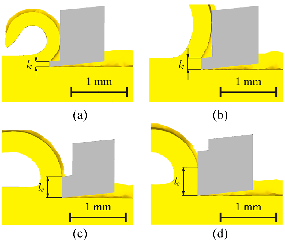
As illustrated in Figure 16, four RCTs presented different tool-chip contact results. According to the contact results of the VL-RCT, all kinds of VL-RCTs could achieve a controlled contact between the tool and chip. The variable-length restricted contact would further reduce the tool-chip contact area than the conventional restricted contact.

Tool-chip contact area at the chip root of different RCTs: (a) R-RCT, (b) RT-RCT, (c) DT-RCT, and (d) T-RCT.
The main cutting force and feed force by different RCTs was illustrated in Figure 17. The VL-RCTs decreased the cutting forces compared to the R-RCT because the VL-RCTs had a smaller theoretical restricted contact area. The main cutting force and feed force of RT-RCT, DT-RCT, and T-RCT were decreased sequentially among the VL-RCTs, indicating that the VL-RCT structure also played a role. And T-RCT reduced the cutting force the best.

The main cutting force and feed force under different RCTs.
The cutting temperature distribution by different RCTs was illustrated in Figure 18. Compared with R-RCT, VL-RCTs could significantly reduce the high-temperature area on the workpiece, indicating that VL-RCTs were more capable of reducing cutting heat. As shown in Figure 19, the temperature variation proved that the VL-RCT could reduce the machined surface temperature, and T-RCT had the lowest cutting temperature on the machined surface. Additionally, the cutting temperature of T-RCT was lower than that of DT-RCT for the same restricted contact area, indicating that T-RCT had a smaller thermal impact on the machined surface.

The cutting temperature distribution under different RCTs: (a) R-RCT, (b) RT-RCT, (c) DT-RCT, and (d) T-RCT.

The temperature variation curves of the fixed points under different RCTs.
As shown in Figure 20, the temperature distribution on the tool surface reflected that the restricted contact structure affected the cutting temperature. As the restricted contact area decreased, the high-temperature area decreased, and the restricted contact structure influenced the high-temperature area as well. The high-temperature areas of VL-RCTs were significantly smaller than those of R-RCT, indicating that VL-RCTs reduced the tool surface temperature, optimized the tool-chip frictional contact environment, and reduced the cutting heat. It confirmed that restricted contact structure not only influenced the temperature in the machining area but also had an important significance on the temperature distribution.

The cutting temperature distribution of different RCTs: (a) R-RCT, (b) RT-RCT, (c) DT-RCT, and (d) T-RCT.
Figure 21 showed the shear angle in the cutting process under different RCTs. The shear angles of VL-RCTs were larger than those of R-RCT, indicating that the variable-restricted contact structure can reduce the material deformation and cutting force. The cutting forces were also verified in Figure 17, which revealed the intrinsic mechanism of VL-RCT to reduce the cutting forces.

The shear angle in the cutting process under different RCTs: (a) R-RCT, (b) RT-RCT, (c) DT-RCT, and (d) T-RCT.
Further analysis of the shear angle by equation (3) showed that the shear angle variation was related to the friction angle when the rake angle was the same. It could be inferred that the VL-RCT led to an increasing shear angle and improved cutting performance by reducing the friction angle. The reduced friction angle indicated that the tool-chip friction of VL-RCTs was better than that of R-RCT. The shear angle of T-RCT was the largest and its friction angle was the smallest, indicating that T-RCT was more conducive to improving cutting performance and tool-chip friction, revealing the reasonableness of the T-RCT design.
Experimental analysis
Cutting force
The cutting performances of different tools were analyzed in depth by actual experiments. Figure 22 demonstrated the main cutting and feed forces by different tools under Vc of 79.2 m/min, t0 of 2 mm, and a feed of 0.2 mm/r. Under the same cutting parameters, the main cutting force and feed force of RCTs were significantly lower than those of CT, indicating that the restricted contact structure could effectively reduce the cutting force. Compared with CT, the main cutting force of the RCTs was decreased by 14.84%–27.72% and the feed force was decreased by 20.49%–30.39%, which was mainly attributed to the improvement of cutting performance and tool-chip friction characteristics. Combining the actual cutting experiments and the finite element simulation results, the simulation and experimental results of different RCTs cutting forces were consistent, indicating that the finite element simulation could effectively reflect the real results, allowing the simulation conclusions to guide the actual cutting.
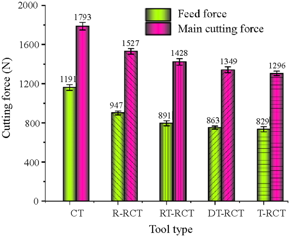
The main cutting force and feed force by different tools.
In addition, the main cutting force and feed force of VL-RCTs were smaller compared with R-RCT. The smaller the tool contact area, the greater the cutting force reduction, indicating that the contact area was an important factor in the restricted contact effect. Under the same contact area, T-RCT reduced the main cutting force and feed force most significantly, indicating that the restricted contact structure also affected the restricted contact effect. T-RCT produced the minimum cutting forces, which provided a reference for the restricted contact structure design.
Cutting temperature
Different restricted contact structures not only influenced the cutting forces and friction but also affected the cutting temperature. The thermal emissivity of 316L austenitic stainless steel was calibrated at 0.7 based on the Fluke Guidebook. When the cutting experiment was conducted up to 120 s, the infrared thermal imager began measuring and recording cutting temperatures. Three measurements were taken for each set of experiments and averaged as the final result.
Figure 23 demonstrated the infrared thermal imager results of different tools. The cutting temperature of CT during machining was significantly higher than the temperature of RCTs. The maximum cutting temperatures of CT, R-RCT, and RCTs decreased sequentially, and the high-temperature area also decreased sequentially. It was consistent with the workpiece temperature distribution in Figure 18 and the maximum temperature variation in Figure 19, thus proving the accuracy of the simulation results.

The infrared thermal imager results: (a)–(e) the infrared thermography of CT and RCTs and (f) the cutting temperature.
Chip curling degree
As shown in Figure 24, the chips obtained by different tools had different curling degrees, resulting in different curl radii. As shown in Figure 24(a), the chip curl radius prepared by CT was the largest, while the one prepared by T-RCT was the smallest. It was because as the tool-chip contact length decreased, the friction and cutting temperature reduced, leading to a larger bending moment and curvature radius of the deformed chip. Figure 24(b) demonstrated detailed values of the curl radii, and the VL-RCTs could further reduce the chip curl compared to the R-RCTs. Notably, the chip curl radius was reduced by approximately 44.7% and 32.9% prepared by the T-RCT compared to the CT and R-RCT, respectively.

(a) Morphology of curled chips obtained by different tools and (b) the measured chip curl radii.
Discussion
As mentioned in the Introduction, existing related studies were mainly focused on constant-length restricted contact tools and few reported the force-thermal characteristics during the cutting process. However, through the finite element method, Ma et al.30,31 found that the rake face length and tip radius of the restricted contact tool could affect the cutting force and temperature. The conclusion indicated that the maximum reduction of the main cutting force and feed force of AISI 1045 steel using RCTs was 4.9% and 15.8% respectively, and that of cutting temperature was 12.9%. In this study, T-RCT could reduce the main cutting force, feed force, and cutting temperature by 27.7%, 30.4%, and 30.8%, respectively, compared to CT. Accordingly, the novel tool structure effectively increased cutting performances and improved the tool-chip contact environment.
To clearly compare the simulation results with the experimental conclusions, the cutting forces and temperatures by different tools were shown in Table 5. The experimental values of cutting temperatures were generally larger than the simulated values, with a maximum relative deviation of 17.5% and an average deviation of 14.24%. For the cutting forces, the experimental values of both the main cutting force and the feed force were smaller than the simulated values. Nevertheless, the simulation results of the main cutting force were more accurate compared to the feed force, with an average relative deviation of only 9.76%. Overall, the simulation results were basically consistent with the experimental results and could reflect the actual machining process.
The comparison of the simulation and experimental results by different tools.

Conclusion
This paper presented a novel design of the VL-RCT to reduce the cutting temperature and increase the tool life. The finite element models of CT, R-RCT, and VL-RCTs were established and corresponding actual tools were fabricated for comparative experiments. Through thermal and force characteristics, the mechanism of RCTs was analyzed. Combining the simulation and cutting experiments, the effects of cutting parameters, restricted contact length l, and tool types were investigated systematically. The main conclusions were summarized as follows:
(1) For both CT and R-RCT, the cutting force decreased with increasing Vc and decreasing t0, and the cutting temperature tended to increase with increasing Vc and t0. Under different cutting parameters, the simulation results showed that R-RCT improved cutting performance more significantly compared to CT.
(2) When cutting with RCTs, the cutting force and the cutting temperature increased as the restricted contact length and restricted contact area increased. RCTs could improve the friction conditions of tool-chip contact to reduce the cutting force and the cutting heat during machining, thus enhancing the cutting performances.
(3) Based on the finite element analysis, cutting experiments were carried out to investigate the effects of different restricted cutting structures on the thermal-force characteristics during the cutting process. The finite element simulation results were consistent with the cutting experimental conclusions. The mechanism of improving the cutting performance by RCTs was investigated, which provided an important reference for the tool structure design and the cutting parameters selection.
(4) Among the four RCTs, T-RCT produced the lowest cutting force and the cutting temperature under the same conditions. Additionally, T-RCT significantly decreased the chip curl radius, indicating that it could improve the tool-chip contact interface and reduce friction. Considering the significant ability to improve cutting performance and reduce tool wear, T-RCT was the most favorable among the VL-RCTs.
As a novel tool design, the VL-RCTs improved the tool-chip interface environment and increased tool life. And this research laid the foundation for the structural optimization of advanced cutting tools, and the selection of machining parameters. In the field of cutting difficult-to-machine materials, this study also provided a new idea and efficient method.
Footnotes
Handling Editor: Chenhui Liang
Author contributions
Rujie Li: Conceptualization, Methodology, Software, Validation, Data curation, and Writing – original draft. Peixuan Zhong: Investigation, Validation, and Software. Yalong Zhang: Resources, Supervision, Funding acquisition, and Project administration. Xueqin Pang: Methodology and Writing – review & editing.
Declaration of conflicting interests
The author(s) declared no potential conflicts of interest with respect to the research, authorship, and/or publication of this article.
Funding
The author(s) disclosed receipt of the following financial support for the research, authorship, and/or publication of this article: This work was supported by the Youth Research Funds Plan of Zhengzhou University of Aeronautics (23HQN01001); Natural Science Foundation of Guangdong Province (NO. 2022A1515010995); and Talent Funds Plan of Yunnan Open University (YNOU04006).
Data availability
The authors do not have permission to share data.