
Abstract
To meet the various demands for bus platforms tailored for the emerging new power sources, an adaptive design method is proposed for a bus chassis development using a design structure matrix. The structural feature parameters of the product modules are extracted and the corresponding design structure matrix is established to analyze structural correlations between modules. An adaptive design method process model is constructed following quantification of the design structure matrix. A digital matrix of the module interface is then built to characterize integration and interchangeability of functional modules. Reconfiguration of modules is conducted using the parent-child relationship premise so that the interface matrixes are well integrated. The adaptability of these products is subsequently improved by sharing dominant modules and replacement of local modules. Finally, the implementation of the proposed methodology is illustrated for a current bus chassis.
Introduction
To help reduce climate change and negate the negative environmental impacts from fossil fuels, new clean energy powertrains are emerging in the bus industry.1,2 The chassis is the support system and installation point for these power systems and it plays an essential role in the overall performance of a bus. This means that for a bus the diverse power sources such as battery, hybrid power, fuel cell, and super capacitor should be mountable on the chassis.3–5 Effective integration of the different power sources with the bus chassis is key to developing an environmentally friendly bus product. Electrification of the power train requires a reconfiguration of the chassis. The traditional bus chassis manufactured for a traditional diesel engine system cannot satisfy the various demands on a bus platform for integration of an emerging new power source. Therefore, there is an increasing industry demand to develop a new bus chassis design with better scalability and flexibility. 6
Adaptable design is a progressive innovation design method which is applied to existing products and technologies to, for example, prolong the life cycle of a product. The underlying philosophy of adaptive design is to obtain new products that meet the needs of the changing market and end-users by mutating some functions, principles and structures of the existing products, to make a product more adaptable.7–9 One typical application of the adaptive design methodology is in the design of products using the modular concept, and this is achieved through the updating, addition, subtraction, or replacement of the functional module. 7 Modularity gives rise to characteristics such as lower cost, product variety, and helps to increase efficiency of the production process in a bus manufacturing company and is deemed a positive solution for development of new energy powertrains for upgrading of traditional urban buses.10–12 Defining modules is an essential step for adaptive design and publications have illustrated how to design modules. For example, Ulrich13,14 defined that modular architecture as having a one-to-one mapping, from functional elements to the physical components of the product. Modular architecture allows manufacturers to cost-effectively develop complex products and product families by decomposing them into simpler sub-units or modules of components. 15
There have already been positive contributions concerning the theory and application of modularity for the bus chassis. For example, Schuh et al. 12 developed a modular chassis product platform to fulfill the requirements of electrified compact and subcompact cars; Millo et al. 16 developed a new hybrid bus for urban public transportation by integrating an innovative hybrid propulsion system featuring a plug-in series architecture into the chassis of an older IVECO 490 TURBOCITY, this relies on a modular approach with the powertrain customized for size and power, depending on the specific application.
Importantly and highly relevant for this current research, Peng et al.17,18 introduced a digital expression method for describing the characteristics of interface geometry information using two matrices with mapping relationships in a practical bus chassis modular design and proposed criteria for assessing the interface connectivity in bus chassis modules to improve the modular design of the bus chassis. With the new generation information technologies used in industry and for product designs there is a move toward digital twins. This new emerging and fast-growing system connects the physical and virtual worlds and can be used to increase a product’s adaptability to changing requirements.19,20
In product architectures the modules are defined to maximize module independency. 21 The information on functional and/or physical interrelationships between components are mainly utilized to identify modules and evaluate the degree of modules’ independency.22–24 Many modularity measures and clustering algorithms have been more focused on utilizing matrix-based approaches.25,26 A design structure matrix (DSM) is a common tool for modular design of products, it was initially introduced by Steward and has since found a widespread application in the design engineering community for modeling and analyzing system architectures.27–29 The potential of DSM was further developed when it was used for system elements clustering analysis to generate various modular configurations. 30 Hölttä-Otto et al. 25 developed metrics to measure the degree of modularity of the system; Sinha et al. 30 introduced a novel approach for a DSM-based architecture modularization; Cheng et al. 31 used a DSM to express dependence relationships between parts, and change propagation trees of affected parts within modules as they are constructed. These examples demonstrate that DSM is an effective tool to solve the problem of the degree of correlation between modules.
When a component changes in a module, it can easily propagate to other modules and can cause multiple system-wide cascades because of the interfaces among modules. 32 In terms of module dependency, publications have described this methodology. For example, Asikoglu and Simpson 33 proposed a method to define design dependencies in a product architecture. Cheng et al. 34 presented a method for coupling analysis between association modules and decoupling strategies in product family design by utilizing the coupling degree and correlation impact degree between modules to depict and analyzes the coupling. In comparison to previous research, this paper aims at a highly bespoke chassis with small batch requirements for adaptation to different new power sources in the bus industry. We have introduced a new simplified quantification method for the degree of correlation between modules. The degree of correlation of each component module of the product can be determined by comparing the value of the structural correlation α. This forms the basis of adaptive design for the bus chassis, particularly in the bus truss type chassis assembled with many non-standard structural components that needs to be adapted for the various new powertrains.
In this study, a simplified quantification method for the degree of correlation between modules is proposed with DSM and evidence theory, this builds a process model of product adaptive design based on quantified inputs. A digital matrix for characterization of functional module interfaces was constructed, and the connectivity and design parameters of the modules were identified using matrix relationships. Finally, the proposed method is illustrated by taking the adaptive design of a real bus chassis as an example.
Product design method based on design structure matrix
When the module selected for function change is redesigned, the structural correlation between modules creates a specific constraint which is applied on the redesign of the module. The size of the constraint is closely related to the strength of the correlation. In order to quantify the degree of correlation between the modules and guide the product’s adaptive design based on quantitative results, the product’s design structure matrix was established.
Parameter-based design structure matrix
Design structure matrix (DSM) is a tool for planning analysis of product development process, it indirectly expresses the information dependencies between variables in a complex process in matrix form and can be divided based on behaviors, parts, parameters, and teams according to the application methods.27,35 This is used to extract structural feature parameters of the product component module, establish a DSM model based on parameters, and digitize the degree of correlation between modules through quantitative criteria. The row and column elements of the DSM model are structural feature parameters of the product composition module, and the links between the row and column elements represent the links between the module structures.
Establishment of quantitative criteria
The degree of correlation between the structural parameters of the modules was analyzed, and the DSM was digitized using a five point scale method. 36 Table 1 shows the five types of weightings and their meanings.
The weightings and meaning of five-point scale method.

Quantified expression of the design structure matrix
The correlation between modules is assumed to be mutual and the degree of correlation is equal. Therefore, the DSM constructed in this paper is a symmetrical matrix, as shown in Figure 1. Each element in the matrix represents the degree of correlation between the two parameters of the corresponding row and column of the element. The elements on the main diagonal are meaningless and are replaced by *. The degree of correlation expressed by other elements is defined by the five-point scale in Table 1. After the matrix is constructed, the rows are accumulated and summed. For example, if the row of the characteristic parameter A-1 is summarized as the correlation degree A-1R, the correlation between the characteristic parameter and other modules can be reflected. Then accumulate all the feature parameter rows of module A, and the resulting AR reflects the degree of correlation between module A and other modules. The structural correlation
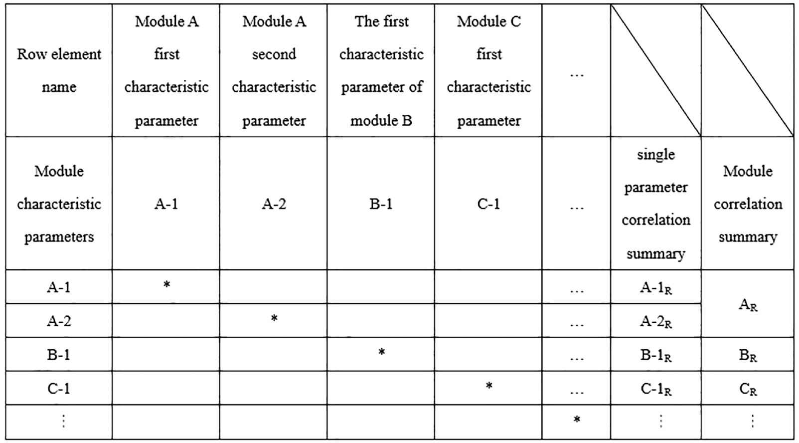
Schematic diagram of DSM quantitative expression.
Simplified calculation of design structure matrix
In order to avoid the issue that the DSM rows and columns are too long and the relationship between the structural features of the modules is not obvious due to introducing too many feature parameters of the product component modules, a simplified DSM quantification method is presented below.
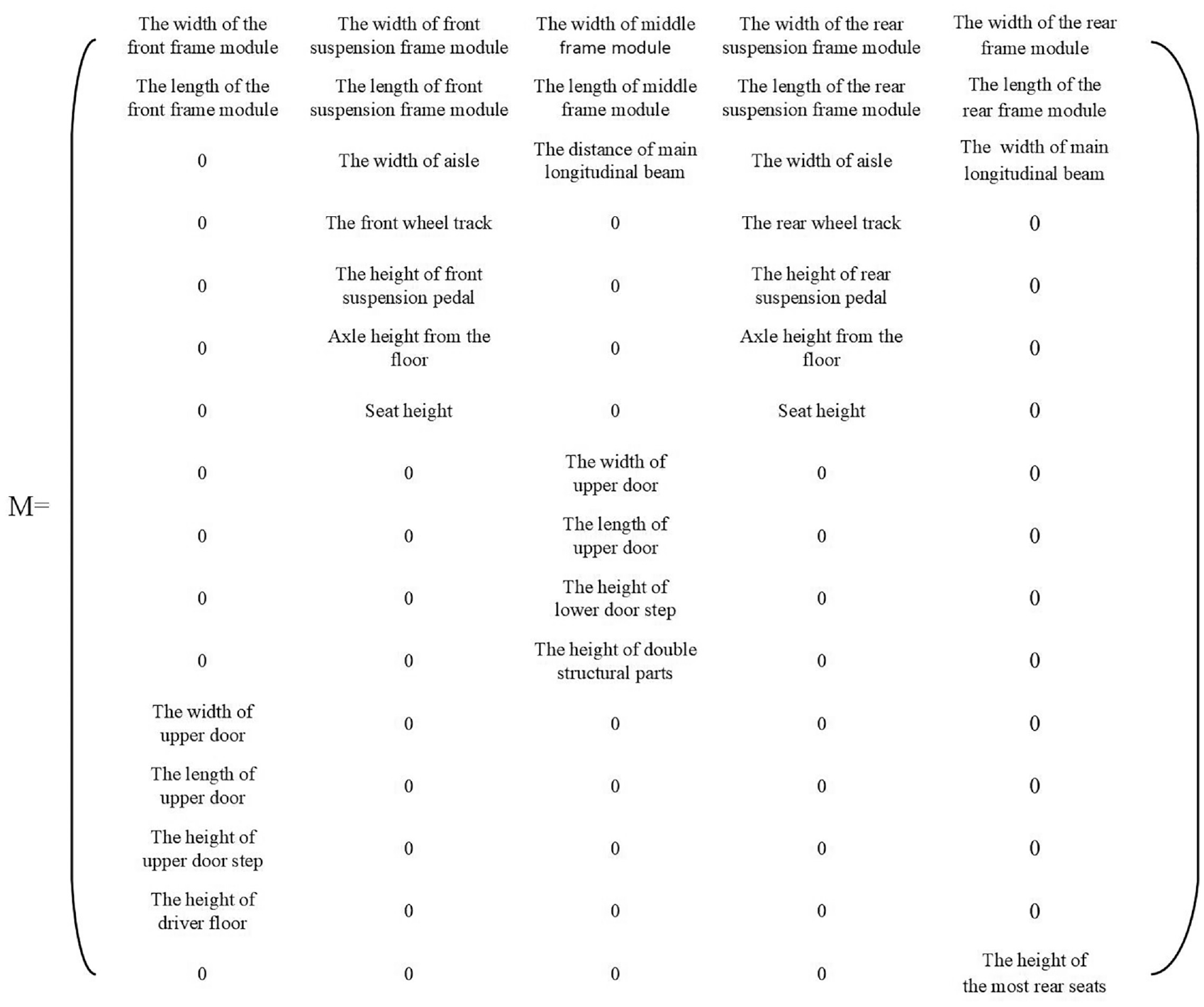
The DSM model used to reflect the degree of correlation between modules is simplified as a structural correlation matrix. As shown in Figure 2, each column in the matrix M represents a different feature parameter in the same module, and each row represents a feature parameter that is from a different module but has a correlation. The element of Mij in the matrix represents the j-th feature parameter of the i-th module. When it is 0, this module does not have this feature parameter, there is no correlation between this module and other features of the module. When Mij exists and is not 0, this module has this characteristic parameter. If there is another non-zero real value at the same time on the i-th row, it means that the module corresponding to the two real values has a certain correlation with this parameter.

Structural correlation matrix M.
The correlation weightings of feature parameters of other modules and other module feature parameters are analyzed in turn, and other parameters with the same weight level associated with the same feature parameter are placed on the same line. Then the correlation matrix

When the element Mij in the matrix M is not 0 and there are k non-zero real values in the i-th row at the same time, it means that the value of the associated module of the j-th module on the i-th feature parameter is k, and the analog matrix of this module is obtained by analogy. Then we analyze the correlation weighting levels of each feature parameter of a certain module. These weightings are shown in Table 1, and establish the module’s associated level matrix Q, as shown in formula (2).

The structural correlation degree α of a single module is calculated as shown in formula (3):

Product adaptability design method
The purpose of the DSM analysis is to analyze the degree of correlation between the feature parameters of each module, after summarizing and comparing, the degree of correlation between each module is known. The greater the value of the module correlation degree, the stronger the degree of correlation of the module with the other module. This means that the constraints on the redesign of the module and the greater the ability to restrain other modules are known. The module with the largest value is defined as the primary module, and the other modules are defined as secondary modules. Based on this, an adaptive design method for existing chassis products is proposed. The process model for this method is shown in Figure 3, and the specific steps are as follows.
(1) Partition of product modules. With comprehensive consideration of product internal and external factors, the module is partitioned. Internal factors refer to the relevant characteristics of the product itself (functional correlation, structural correlation, physical correlation) in the case of functional principle determination, and external factors refer to changes in customer requirements, including changes in the scope of the functional domain and the strength or size of the function.
(2) Quantification of the degree of correlation between product modules. From the characteristic parameters of the product composition module, establish the structure correlation matrix of the product module, calculate the correlation degree of each module according to the correlation degree calculation formula and compare them. The initial main module and the sub-module can then be established.
(3) Determination of target-type functions and structural parameters. Analyze the market or user’s needs, map the requirements to the functional and structural characteristics of the product, and compare them with the functionality and structure of existing products to identify the components and modules that need to be added, removed, replaced, or redesigned.
(4) Redesign or reconstruction of the main module. On the basis of establishing the functional and structural characteristics of the new product, the initial main module is given priority, redesigned or reconstructed, and a digital interface matrix of the main module is constructed.
(5) Redesign or reconstruction of pre-connected submodules. Construct the digital interface matrix of the pre-connected sub-module, confirm that the interface matrix of the primary and secondary modules meets the requirements of the module connectivity, and then redesign or reconstruct the sub-module.
(6) Module connection and integrity verification. Implement the connection of the primary and secondary modules and check the integrity of the function and structure of the combined module.
(7) Design cycle of the product composition module. After confirming the integrity of the function and structure of the combination module, this combination module is used as the main module of the next round of design cycle occurs and steps (4)–(6) are repeated.
(8) Complete the product’s adaptive design. Repeat steps (4)–(7) until all product modules are redesigned and connected, and check the functionality and structural integrity of the product.

Product Adaptability Process Design Model.
Expression design of module interface matrix
Module partition of product
A modular design concept is used to adapt the product to the design. The essence of the product is to improve its adaptability through the update, increase or decrease or replace the function module, and to meet the requirements of user customization and market diversification. This design method mainly includes two basic processes: module partition and module combination. Reasonable and effective module partition is the premise and foundation of product modular design. The same object considers different angles, and the module partition will be different. 37 However, in general, the partition of product modules should meet the most basic requirements. This entails that there is a reasonable mapping between the functional decomposition tree and the structural decomposition tree, and the interaction between the constituent elements of the structural tree is minimized, as shown in Figure 4. 10
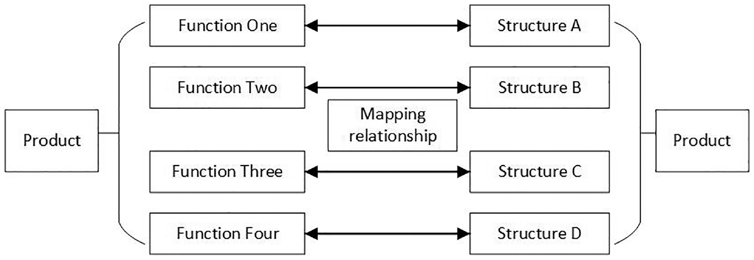
Product function and structure decomposition diagram.
On the basis of module partition, the adaptive design of products for functional changes and performance enhancements depends on the combination of modules. In order to realize the combination of different functional modules and the replacement of the same function and different performance modules, the module should have two characteristics of integration and interchangeability. Both of these features are mainly reflected in the interface of the module. The updating, addition and subtraction, and replacement of the functional modules that can be implemented under the premise that the interface can be connected can make the existing products tend to function ideally.
Digital characterization of module interface
The scope of use of the module is restricted by the shape of the interface topology, there is currently no effective way to characterise the interface of the module for a certain type of function without very significant mosaic-type feature interfaces.37,38 This paper proposes a novel digital representation of the functional module interface and this can be used to represent a variety of structural interfaces in a variety of structural styles. It also identifies the structures and parameters that are variable and constant when the module is redesigned. A matrix is used as the digital representation of the module’s feature interface. It is a characterization parameter that uses the module’s interface and is constructed according to a specific sorting combination. According to a specified partition principle, a product is partitioned into its modules.
Assuming that the

The matrix of variable parameters is deconstructed into a column matrix for each element. That is

If and only if each element of the interface matrix
Case studies
Module partition of the bus chassis
The bus chassis consists of five modules which are partitioned according to their function and layout in the vehicle, as shown in Figures 5 and 6, namely the front frame module, the front suspension frame module, the middle frame module, the rear suspension frame module, and the rear Segment module.14,15 The front frame module includes the passenger door area, the driving area, and the minority passenger standing area. The front suspension frame module includes two side seating areas and a central passage area. The middle frame module is mainly for the area where most passengers ride and the passenger access area. Included in the rear suspension frame module are two sides of the seat area and the central passage area. The bottom of the rear frame module is used to carry the engine, intake and exhaust system and other devices, with a small number of seats above the floor.

Schematic diagram of the chassis module partition.

Bus chassis module partition.
The adaptive design method applied to the bus chassis
The following steps are undertaken. Extract the feature parameters of the coupling surface of the undercarriage module of the bus, analyze the associated weighting levels among each parameter in turn, and construct an inter-module structure correlation matrix M and the weighted level moments of each module Q. From this, the associated numerical matrix M is obtained and the correlation degree α of each module is solved by the formula. The matrix M as shown in Figure 7 and the results are shown in Table 2.
Quantification for the degree of correlation between bus chassis modules.
Quantification results of the degree of correlation of the chassis module.

The calculation results in Table 2 indicate that the structure of the front suspension and rear suspension frame modules in the five modules are the largest, and equal, followed by the middle module and the back module, and the correlation of the front module is the smallest. According to the results of this evaluation of the degree of correlation, the former suspension module was used as the initial main module to establish the adaptive design process model of the bus chassis, as shown in Figure 8. The front module, front suspension module, middle module, rear suspension module, and back module are referred to as module A, module B, module C, module D, and module E in sequence, respectively. Taking module B as an example, the interface matrix near the front of the vehicle body is abbreviated as p-B, and the interface matrix near the vehicle rear is B-p, and the interface matrix of other modules is the same as this.

Adaptable design process model of the bus chassis.
Redesign or reconstruction of modules based on digital representation of interfaces
On the basis of the digital representation of the module interface, the redesign of the middle module of the chassis when the energy source of a bus is transformed from traditional fossil fuel-based power to pure electric drive is elaborated in detail.
According to the correlation degree calculation results, the front suspension frame module is defined as the main module. The middle frame module is the sub-module, and the feature parameters of the joint surface of the two modules are extracted. Thereafter, digital matrix of the module interface is constructed, and the middle frame module is satisfied under the requirement of the parent-child relationship of the module interface. This achieves the redesign and implementation of the connection between modules.
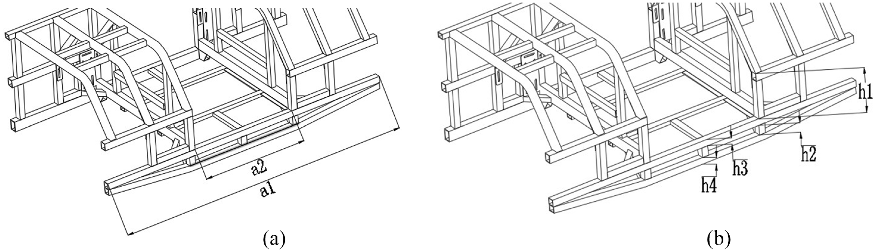
Extracting the characteristic parameters of the front suspension frame module and the middle module joint surface, as shown in Figures 9–12. The overall layout of the bus or other external components such as suspension, seats, and other relevant parameters are defined as invariant parameters, the frame itself can be defined as a variable parameter according to a certain optimization measure of adjustment and design parameters, the statistical results are shown in Table 3. The range of values of the variable parameters of different products and different modules and the real values of the invariable parameters may have different definitions according to the actual conditions of different projects.
Interface parameters of the front suspension frame module B1 (Before design).

Interface parameters of the front suspension frame module B1 (After design).

Interface parameters of the middle module C1 (Before design).

Interface parameters of the middle module C2 (After design).
Module joint surface characteristic parameters (before design).

According to the data in Table 3, the digital matrix of each module interface is established.

According to the actual product conditions, the definition of body width and aisle width are invariable parameters, which are related to the size of the axle and the seat. The height of the double-layer structure, the height of the cross-section of the upper and lower beam rectangular tubes, and the footrest height can be adjusted to within the range defined as variable parameters. The pre-design interface matrix

Connection module B1-C1 connection diagram (Before design).
Module joint surface characteristic parameters (after design).

The digital interface matrix before the middle module design is


Connection module B1-C1 connection diagram (After design)
Adaptability design of the bus chassis
To meet the changing demand for new alternative energy power systems in a family of new buses, on the basis of the quantification of the degree of correlation between modules and the digital representation of the module interfaces, an adaptive design study was carried out using a bus chassis fitted with a conventional internal combustion engine as the starting point. Changes in axles, suspensions, access doors and seats, etc., were not consider, the focus was on changes in the chassis caused by changes in the power train system, the following improvements have been made: The distance between the two-tier modules of the middle modules has been adjusted and the underlying structural components have been added. To supplement this the middle frame of the module is extended, and the original engine installation frame is removed from the rear frame module removed. On this basis, a modification is made to the height of the seat arrangement. The original layout of the area including the intake and exhaust system is designed to fit the motor and main control box.
The design results show that through the sharing of the front frame module, the front suspension frame module, and the rear suspension frame module, the redesign of the middle module and the replacement of the rear frame module satisfy the matching requirements of the change of the power system to the chassis, and improve the chassis design. Shown in Figure 15 is the adaptability of the bus chassis before and after the design.

Adaptability design of bus chassis.
Discussion
Application scale
This research conducts a case study of adaptive design method using a design structure matrix to solve the technical issues on bus platforms tailored for the emerging new power sources, it provides an effective way for the redesign of vehicle based on the same platform with a series of power source/power train. However, it is not suitable for the case with a cross-platform development or with a thorough different general layout of Chassis.
Complexity degree
This study provides a method using design structure to quantify structural correlations between modules. As the module number significantly grows, potential issues may arise along with the increasing computational complexity. The approach of DSM shall be upgraded and integrated with optimization methods according to the real need, for example, a method of MDDSM (Multi-domain Design Structure Matrix) shall be developed to coordinate the attribution differences of multiple components in complex system design, and a method of EDSM (Extended Design Structure Matrix) shall be developed to reduce the effect of data interaction in collaborative development of complex products.
Mechanical performance
The mechanical performances including strength and stiffness of bus chassis are essential in the development of a bus chassis, with the replacement of modules in a new energy bus chassis, those performances may vary as the module changes. In principle, mechanical performances of modules need to be virtually verified in parallel as a basis, and the modules employed in the modular design typically are considered with acceptable mechanical performance.
Conclusion
Based on the research work presented in this paper, the following has been achieved and demonstrated.
(1) A simplified quantification method for designing structural matrices (DSM). This method greatly reduces the scale of the design structure matrices. At the same time, it can reflect the relationship between the structural parameters of each module directly and concisely. The method is described by quantifying the degree of correlation between the chassis modules of the bus.
(2) An adaptive design method based on the design structure matrix. The process model of the method is established on the basis of the quantification of the structural correlation between the product components. As an example, the adaptive design of the bus chassis is used to study the method, verifies and validates its feasibility and effectiveness. This method can also be applied to the adaptive design of other products.
(3) The construction of a digitized matrix for characterization of functional module interfaces. Further the method is elaborated by using the matrix in detail through examples, aiming at a specific type of feature interface or interface module with inconspicuous mosaic type, and a variety of modules. The digital representation of the interface creates the foundation for the scientific and rational redesign of product modules.
(4) For the bus chassis used as an example to study the product’s adaptability design method, the results show that through the sharing of most of the modules and the replacement of local modules, the requirements for the matching of the power system of new alternative energy vehicles to the chassis are met. The adaptability of the bus chassis is provided a reference value for the design of the relevant bus.
Finally, the evaluation of the degree of correlation between bus chassis modules is based on a certain subjective basis. This evaluation system only serves as a reference for the design of the same series of vehicles, and can be improved and optimized according to actual engineering conditions in the following research process.
Footnotes
Handling Editor: Chenhui Liang
Declaration of conflicting interests
The author(s) declared no potential conflicts of interest with respect to the research, authorship, and/or publication of this article.
Funding
The author(s) received no financial support for the research, authorship, and/or publication of this article.