
Abstract
To solve the power limitation problem faced by the development of EPS system for commercial vehicles and achieve the high-performance steering, this article presents a novel dual power-driven electric power steering system (DPEPS) for commercial vehicles by using the open winding permanent magnet synchronous motor (OPMSM) fed by dual inverter with high and low DC voltage supplies. First, the two-level control strategy is introduced for the developed DPEPS system, where the upper control is designed to make the actual steering follow the expected steering performance as determined by the assistant torque curve and to generate the appropriate target current according to the vehicle speed and steering torque. And then the lower control consists of the synthetical space vector control scheme and dual PI control loop is used to execute commands from the upper control, which can make the motor execute the appropriate power supply method according to the steering torque and assist current. Finally, a co-simulation model is carried out for an electric bus, and based on which the proposed DPEPS system is validated.
Keywords
Introduction
The commercial vehicles, owing to the potential for achieving the higher commuting efficiency, are playing an important role in the domain of public transportation.1,2 Electric power steering (EPS) systems demonstrate outstanding features, such as green environmental protection, high-level efficiency and energy saving, and good steering characteristics, which represents the development direction of intelligent steering in the future. 3 Because the current 12 V (passenger car) or 24 V (commercial vehicle) on-board battery voltage system limits the power of the steering motor, the research on EPS system focuses on passenger car with small forward load, 4–6 while the research on EPS for commercial vehicle with large forward load has not been solved well. Most commercial vehicles today still use hydraulic steering systems due to the limitation of the 24 V supply voltage. 7 When comparing EPS system with hydraulic power steering (HPS) system, the EPS systems show many better performances compared to HPS systems, specifically: (1) The EPS does not need to drive from the engine so the engine does not have to use hybrid power for the power steering system so it will save fuel when operating. (2) The EPS does not use the fluid (hydraulic oil) to drive power, so it ensures more environmental hygiene. (3) The EPS has a simple structure, much lighter than HPS. (4) The EPS gives a more realistic driving feel at high speeds. For HPS, the higher the speed, the lighter the driver makes the driver more susceptible to driving and the vehicle is unstable especially when cornering is urgent. This is completely different for EPS, which requires lightweight support at low speeds and heavy weight support at high speeds, which gives a more realistic and more solid driving feel. With the aim to overcome the shortcomings of the HPS system, electro-hydraulic power steering (EHPS) system is developed for commercial vehicles in Refs.,8–11 where the main principle of the EHPS system is based on a motor to produce hydraulic pressure and reduce the amount of power needed to operate the steering wheel. The system improves fuel economy by reducing the load on the engine. However, EHPS system has inherent complex structure and oil leakage problem.
With the increasing electrification trend of commercial vehicles and the emergence of high-performance motors, new opportunities are brought for the research and development of EPS system for commercial vehicles. 12 For electric commercial vehicles, the high-voltage power battery replaces the fuel system to supply the energy source for the vehicle driving motor system, and can also provide the power source for the development of EPS system with high voltage demand. ZF company invented an EPS system which meets all powertrain concepts while perfectly matching the requirements of electric commercial vehicles and is suitable for a variety of trucks and buses of different specifications. 13 Infineon company introduced an efficient EPS system with active steering for 24 V commercial vehicles, which contributes a new electronic-based steering system. 14 Li et al. 15 presents an EPS system driven by dual motors, in which the master and slave motors are coaxially linked in parallel, enabling the EPS system to produce a major power-assisted torque such that the steering torque requirements of commercial vehicles are satisfied. On the other hand, DC motors were mainly used as steering booster motors in early EPS systems. 16 To increase the electric power assist torque and further improve the performance of the booster motor, permanent magnet synchronous motors (PMSM) and AC induction motors are also widely used in EPS systems.17–20 Especially open-end winding PMSM motor driven by two different inverters as illustrated in Refs.,21–23 where the dual inverter composed of double two-level inverters can produce space vector locations identical to that of a three-level inverter. So, an increase of dc-link voltage utilization in the open-end winding topology is achieved comparing with the two-level inverter fed star-connected winding topology. Therefore, the high-power output capability of the open winding motor system makes it very suitable to be used as a steering power assist motor for electric driven commercial vehicles, unlike the dual-motor driven EPS system in Li et al., 15 which brings complex and redundant structure.
This study proposes a new dual power-driven electric power steering system (DPEPS) for electric commercial vehicles based on OPMSM, which provides a new solution to the power limitation problem faced in the EPS system design of electric commercial vehicles. In summary, the main contributions of this article are illustrated below. Firstly, the basic dynamic model of DPEPS system for an electric bus is established in the Simulink. Then, the two-level control strategy of the proposed DPEPS system is investigated. In the upper-level control, the assistant torque curve map is obtained according to the EPS design requirement. Based on this, appropriate target assistant current is derived. In the low-level control, the synthetical space vector control scheme is designed for the OPMSM fed by dual inverter with high and low DC voltage supplies. Finally, co-simulation between TruckSim and Simulation is presented to verify the proposed DPEPS system and corresponding control strategy for electric commercial vehicles.
The paper is divided into five sequential sections. Section “Dual power-driven EPS system” describes the dual power-driven electric steering system. The control strategy of dual power-driven EPS is investigated in section “Control strategy of dual power-driven EPS.” Co-simulation results illustrating the effectiveness of the proposed DPEPS system are established in section “Co-simulation.” Conclusions are summarized in the last section.
Dual power-driven EPS system
The schematic diagram of the proposed dual power-driven type EPS is presented in Figure 1, where the main components are listed as following:
(1) The torque sensor is used to measure the toque Te between the steering wheel coupled to the worm gearbox.
(2) The OPMSM instead of the commonly used PMSM is responsible for providing the assistance torque, which is the most significant innovation of this paper.
(3) The controller in ECU generates the target torque by controlling the corresponding current according to the multi-sensory input signals.
(4) Friction that occurs at the interface of multiple mechanical structural components is ignored, such as worm gearboxes, bearings, joints, racks, and pinions.
(5) Reaction from road surface to tires.

Block diagram of the dual power-driven EPS system.
The operating principle of the electric power steering system is based on the signal of the torque sensor located in the power steering. When the steering wheel is operated by the driver, it is necessary to change the direction under the effect of the reaction from the road surface through the wheel, and the steering wheel acts on the torsion bar located in the electric power assembly. The torque sensor is responsible to calculate the driving torque (the deformation of the torsion bar) from which to send the signal to the control box. Based on the signal of the torque sensor, the control box gives the motor drive power line large enough to support the steering wheel rotation in the direction of the driver, so the driving force will be supported and become much lighter. Meanwhile, the controller can realize real-time adjustment of driving road feel according to vehicle speed. The steering output torque will decrease as the vehicle speed increases, so as to ensure that the driver has a proper road feel during high-speed steering, and improve driving maneuvering stability, thus achieving safe driving.
Remark 1. This paper proposes a new a novel dual power-driven electric power steering system as shown in Figure. 1, where the dual power comes from the high-voltage power batteries and low-voltage batteries inherent in electric commercial vehicles, which provides a new solution to the power limitation problem of steering motor existed in the EPS steering technology development for electric commercial vehicles. At the same time, when one power supply fails to work, the other power supply can still keep the vehicle running safely, which improves the safety performance of commercial vehicles.
Dynamic model of the dual power-driven EPS system establishes a coupling link between the dynamics of the steering mechanism and the electrical power output of the motor as shown in Figure 2. According to the basic principle of dynamics, the mathematical model of the dual power-driven EPS system as illustrated in Figure 2 can be expressed as


where Js represents the inertia of the steering wheel around the steering column, Ks denotes the stiffness of the steering column, Bs is the damping characteristics of the steering column, Km is the stiffness of motor and reducer, Bm is the friction coefficient of the motor, Jm is the moment of inertia of the motor, Kr is the linear stiffness of rack and pinion, Br is the vibration damping coefficient of pinion and rack, m is the equivalent mass of pinion and rack, Td represents the driver’s torque of the steering wheel, Tm is the output torque produced by the motor,

Structure schematic of the dual power-driven EPS system.
Based on equations (1)–(3), the block diagram of the basic dynamic model of EPS system is established in Simulink as shown in Figure 3.

Simulation model of the dual power-driven EPS system.
Control strategy of dual power-driven EPS
The integrated control strategy of the proposed dual power-driven EPS is based on the two-level control architecture as shown in Figure 4. The upper-level control aims to ensure the actual steering torque conform to the desired steering performance determined by assistant torque curve map and produces the appropriate target current. The dual current closed-loop control method designed for OPMSM in the lower control layer is responsible for implementing the control objectives derived from the upper-level control. The next analysis aims to describe the upper and lower control strategies in detail.

Control architecture of the dual power-driven EPS.
The total weight consisting of spring mass and unspring mass is obtained by using the sensing equipment fixed in the axles, where the spring mass of the commercial vehicle is calculated by testing the elastic deformation of the axles, and the unspring mass is given in advance. With the help of the collected online vehicle speed and spring mass information, the ECU calculate the real-time assistant torque according to the assistant torque curve map that will be explained in the subsequent analysis. The real-time assistant torque command is transformed to the corresponding desired current command based on the positive proportionality between the current and torque of the assistant motor. The desired current is appropriately allocated to the two inverters through the synthetical space vector pulse width modulation (SVPWM) control strategy. The OPMSM motor is manipulated by two dual closed-loop PID controllers to output an assistant torque corresponding to the target current.
Upper-level control
The power assist characteristics play a key role in the performance of electric power steering systems, such as portability, correction, steering road feel, and so on. 24–26 In order to solve the contradiction between lightness and “flexibility” of electric power steering system, The assist characteristics curve should be matched to the specific vehicle parameters and driver requirements for steering portability and road feel. The basic requirements of EPS control strategy design need to follow two aspects. On the one hand, the assistant torque should increase with the driver’s input torque demand to realize light steering. On the other hand, the assistant torque should be reduced to maintain the road feel when steering at high speed. The relationship among the power assistant current, steering wheel torque, and speed is called assistant torque curve, which determines the magnitude and direction of the assistant current of the OPMSM based on the signals from the steering wheel torque sensor and speed sensor. The three commonly used types of power steering assistant torque curve mainly include straight line, broken line, and curve, where the linear power steering assistant torque curve is widely used because of its simplicity, ease of implementation and adjustment. The straight linear assistant characteristic is adopted here and its mathematical equation is expressed as

where I denotes the assistant motor current, Td is the input torque of the driver acting on the steering wheel, Td0 denotes the minimum constraint of the steering wheel torque when the EPS system is working, Tmax represents the maximum constraint of the input torque of the steering wheel, Imax is the maximum current of the assistant motor, k(v) denotes the speed induction coefficient which is defined as k(v) = Imax/(Td−Td0).
The power assistant characteristic of electric power steering system describes the law that the magnitude and direction of power assistant torque change with the vehicle real-time motion state. The mainly principle should be considered as follows:
(1) The electric power steering system should provide a large amount of auxiliary torque for the low-speed commercial vehicle to ensure light and flexible steering. With the increment of vehicle speed, the power assistant torque provided by the power assistant OPMSM motor will become smaller.
(2) When the steering wheel torque is smaller than a preset threshold, no power steering is required and the power assistant OPMSM motor does not work.
(3) The torque obtained from the power assistant OPMSM motor shall be limited to the maximum value, so as to avoid damage to the motor due to excessive steering load.
According to the design principles of the steering characteristics and in combination with the operating characteristics and requirements of the electric bus as a typical representative of commercial vehicles, in this study, the starting torque of the steering wheel is assumed to be 2 N·m, the maximum torque Tdmax of the corresponding steering wheel provided by the assisted motor is 30 N·m, and the upper limit of the assistant current is set to 48 A. The characteristic curves are obtained at intervals of each 10 km/h, Reference power current and the steering torque input by the driver form a straight line under the condition of constant vehicle speed. The power assist slope changes with the time varying of the vehicular velocity, that is, the higher the velocity, the higher the slope. The linear power assistant characteristic curve and corresponding three-dimensional power assistant characteristic curve adopted in this study are shown in Figure 5(a) and (b), respectively.
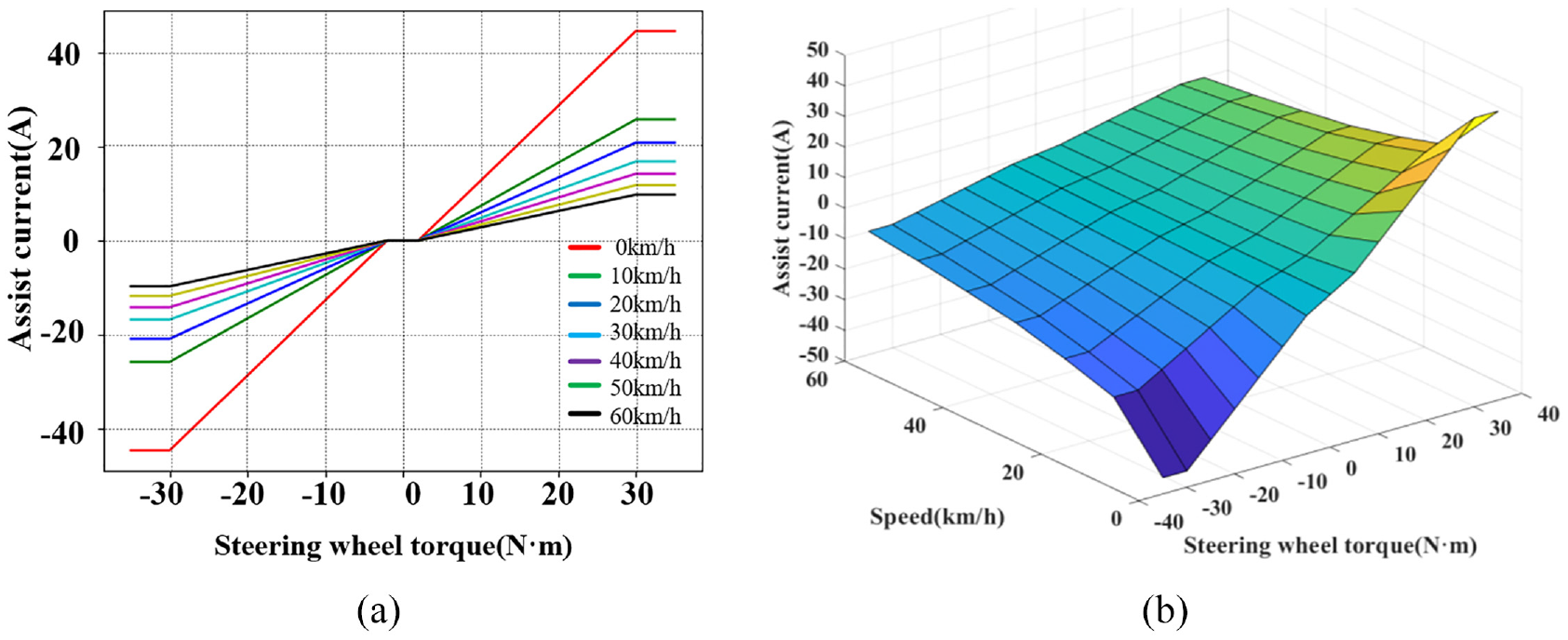
Assistant torque curve map of the proposed DEPS system: (a) The linear power assistant characteristic curve, and (b) corresponding three-dimensional power assistant characteristic curve of the proposed DEPS system.
Lower-level control
In this study, the open winding permanent magnet synchronous motor fed by high and low voltage is used as the power assisted driving motor, in which the high voltage is powered by a 500 V high voltage power battery pack, and the low voltage is powered by a 24 V battery. The topology structure of dual independent output inverter system with two different DC power sources Vdc1 and Vdc2 is illustrated in Figure 6.
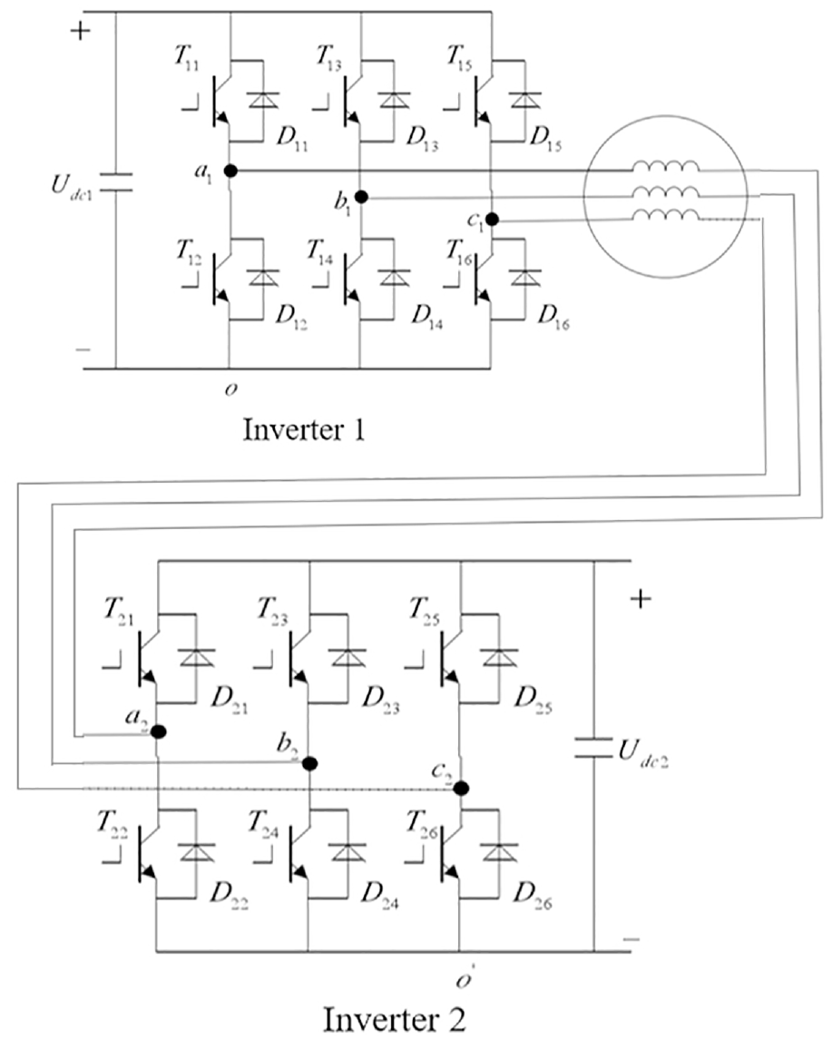
Topology structure of dual independent output inverter.
The inverter section consists of two fixed diode bridge rectifiers which convert the DC voltage into AC power. The output voltage and frequency to the OPMSM are controlled by the control logic and inverter section. Smn (m = a, b, c; n = 1, 2) is used to indicate the switch state of the upper tube of each phase bridge arm. When Smn is equal to 1, the pipe on a bridge arm is connected. On the contrary, When Smn is equal to 0, the lower pipe of the corresponding bridge arm is connected. The stator voltage equation can be expressed

where u1, u2 represent the DC bus voltage of two inverters,
The transformation of space vectors is important for various PMSM motor controls since it can simplify the control design by transferring a complex three-coordinate system to a two-coordinate system or transferring a time variant system to an invariant system.
27
This transformation mainly includes following two steps, that is, (1) Clarke transformation

where
The torque equation and motion equation are respectively calculated as
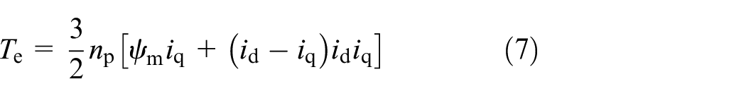

where
Space Vector Pulse Width Modulation (SVPWM) is a technique used in the last step of Field Oriented Control (FOC) to calculate the pulse width modulation signal of the inverter switches so as to produce the required three-phase voltage for the PMSM. With the remarkable features of large linear control range, less harmonic distortion, and fast transient response, SVPWM technology is considered as an effective solution for PWM voltage source inverters. 28 For a classical three-phase voltage source inverter (as shown in the left half of Figure 6), each pole voltage may assume one of two values (1 or 0) depending on whether the upper or lower switch is turned on. For the dual independent output inverter system as shown in Figure 6, a synthetical SVPWM algorithm inspired by Chen and Sun 29 is introduced here, where the zoning in the sector is determined based on the mapping between the duration of the initially applied voltage vector and the sampling.
The reference voltage vector ur depends on the output of the dual inverter, such that

where
The synthetical SVPWM approach is running based on equation (9), where every inverter outputs an active voltage vector, that is,

where
Table 1 describes the time distribution for the voltage vectors of the two inverters in the various parts and corresponding locations, where
Time selections of voltage vectors for the two inverters.

The superposition of the desired voltage vector in three locations of section 1 is illustrated in Figure 7. In the case of
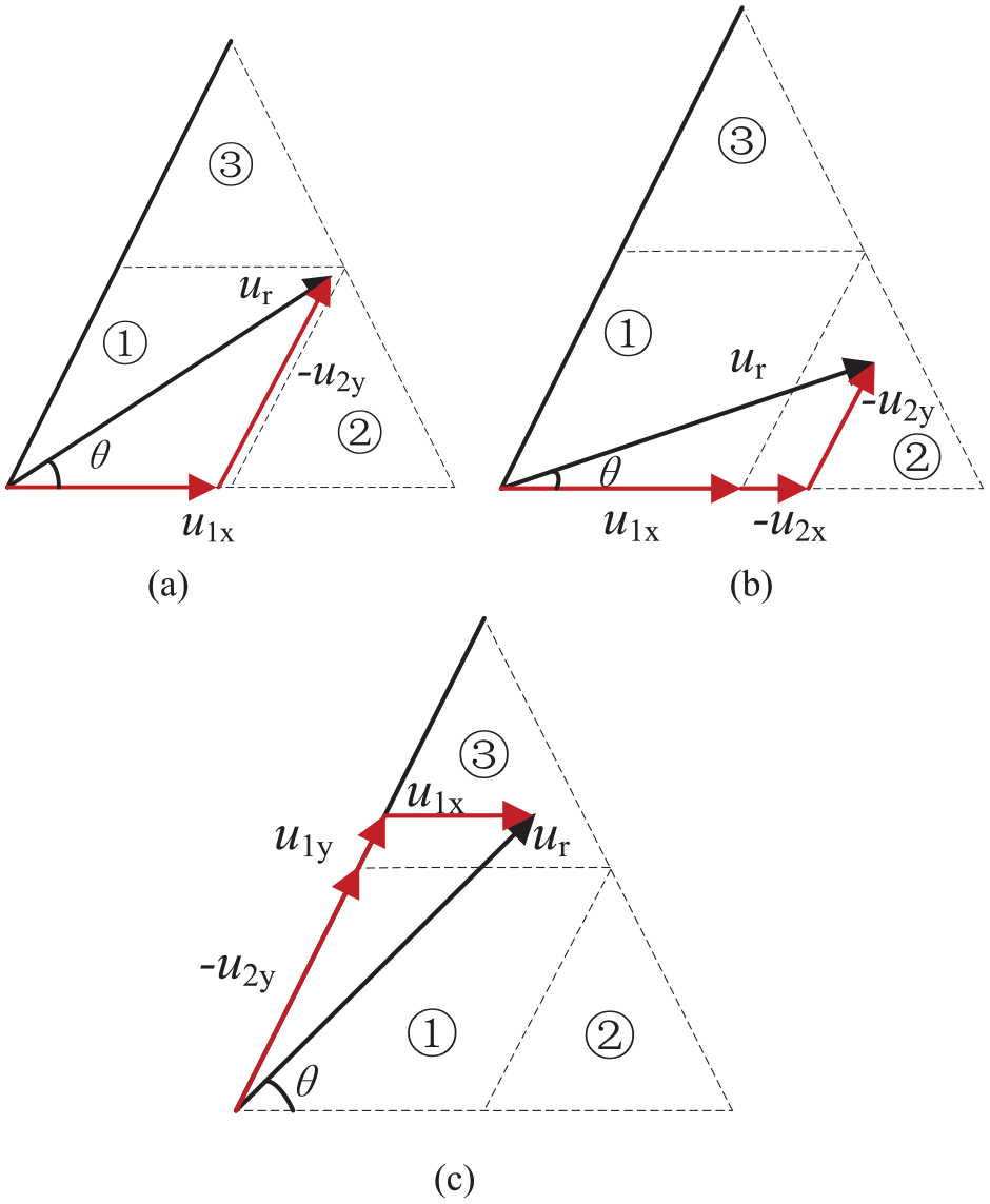
Space vector synthesis diagram in location I: (a) Uris situated in section 1, (b) uris situated in section 2, and (c) uris situated in section 3.
To sum up, the logical selection rule of space voltage vector for the two different inverters is shown in Figure 8. The numbers

Overall space vector synthesis diagram.
Vector control is an effective method widely used for PMSM motor control. Magnetic field directed control is introduced to control the space vectors of flux and stator current, where the synchronous coordinate frame used in the controller design allows the stator current vector to be decomposed into a magnetic field component and a torque component. The sampled three-phase currents can be transformed by Clarke and Park to obtain the d-q axis currents of the motor in the synchronous rotating coordinate system. d axis is the straight axis (i.e. the axis coinciding with the main flux direction of the motor rotor) and also the excitation axis, and the excitation field size can be changed by controlling the d axis currents, which is generally used to achieve the maximum torque-to-current ratio control, and can also be used as a weak magnetic control to achieve the speed above the rated speed. The q-axis is the cross-axis (i.e. the axis perpendicular to the main flux direction of the motor rotor) is also the torque axis, and the torque magnitude can be changed by controlling the q-axis current, which is simply understood that the motor output torque is proportional to the q-axis current and d-axis magnetic field. But what we can control is the on/off of the three inverter switching tubes (i.e. we can only control the magnitude of the line voltage/phase voltage), and we cannot directly control the three-phase current, so we need to introduce feedback control to calculate the actual d-q-axis current, generate the target d-q-axis voltage through PID controller calculation, and then conduct SVPWM modulation to generate the PWM signal to control the switching tubes, so as to realize d-q axis current control. As for the more outer-loop speed control, under the control strategy with id = 0, it is the target value of the cross-axis current of the target (i.e. iqref) that is calculated by the PID controller. The target value of the cross-direct axis current is obtained differently under different strategies.
Based on the basic principles of classical vector control described above, the control diagram of the proposed DPMSM is shown in Figure 9, where the control schemes of the OPMSM system consists of two closed-loops. Namely, The PID speed control in the outer loop is used to follow the target speed, while the current control in the inner loop is used to achieve the target current tracking. The control of the stator current can simply consist of two digital PI controllers, which then perform some basic mathematical operations to calculate the PWM duty cycle of the proposed unified SVPWM and generate the driven pulses for the two inverters. Since the d and q axes are coupled, a decoupling network is required in order to achieve independent control of each current component. As described in Nehaoua et al., 20 the magnetic field-oriented control (FOC) method is mainly used as a torque controller. Therefore, the reference current in d-axis is usually selected as zero to maximize torque generation.
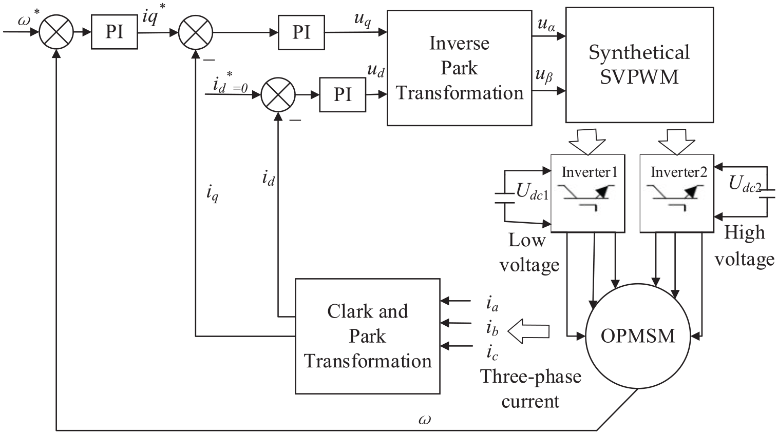
Control diagram of OPMSM.
Figure 9 shows a possible implementation of the FOC current controller using Simulink. The two PIs in the d and q axes and the decoupling network between them can be identified. the saturation limits of the PIs are dynamically set according to the dc bus voltage.
Remark 2. The OPMSM motor driven by dual sources and dual inverters is very suitable for pure electric vehicles or hybrid electric vehicles powered by different dual sources of high and low voltage, respectively. The power output capability and fault tolerant operation capability of the OPMSM are better than those of the traditional PMSM. In this paper, a synthetical space vector modulation method based on dual two-level voltage source inverter system is proposed. The basic idea is that each inverter provides an valid synthetical voltage vector that can produce the same effect when synthesizing the reference voltage vector in the single inverter SVPWM algorithm, such that synchronous control of two inverters is achieved. The synthetical space vector modulation method is suitable for any voltage ratio, so that it is not limited by the DC power supply voltage ratio at both ends of the dual inverter system.
Co-simulation
In this section, a joint simulation has been carried on to illustrate the feasibility of the developed DPEPS system for an electric commercial vehicle. A dynamic simulator was constructed using Trucksim and MATLAB/Simulink, which can approximate real commercial vehicles dynamic and verity the closed loop control strategy. Here, an electric bus vehicle as a typical commercial vehicle model embedded in Trucksim was established. The bus steering dynamics were simulated by Trucksim based on input/output data, which are needed to verify the closed-loop control strategy, and the developed two-stage control approach was programmed in MATLAB/Simulink. The real-time status and control output of the steering system interact through the export and import channels, respectively. The block diagram of the proposed co-simulation is shown in Figure 10.

Block diagram of the co-simulation.
First, we verify the lower-level control for the two dual power driven OPMSM. Table 2 presents the parameters of the DPEPS system for the bus vehicle, and the simulation conditions are set as follows: the dc-link voltage is respectively selected as 500 V and 24 V for the dual inverter, the motor speed is set at 500 rpm, and 20 N·m load torque is added at 0.5 s. The simulation results of OPMSM are shown in Figure 11. It can be seen that the motor speed reaches the target speed in a very short time and remains stable after adding the load torque, and the three-phase current corresponding to the torque changes rapidly when the motor is affected by the load torque, which illustrate the effectiveness of the developed synthetical space vector control performing on the OPMSM motor.
Parameters of the DPEPS system for the bus vehicle.


Control performance of OPMSM.
It is assumed that the steering wheel torque is a sinusoidal signal with amplitude of 20 N·m, the power assistant current at two different vehicle speeds can be obtained as in Figure 12. It is noted that the power assistant current demonstrates a good performance with the steering wheel torque and meets the characteristics of the power assisted characteristic curve as depicted in Figure 5. It also can be seen from Figure 13 that the amplitude the steering wheel torque input is increased to 50 N·m when the steering wheel torque is less than the threshold (Td0 = 2 N·m), no power is provided and the power assistant current is 0 A. After that, the power assistant current increases from 2 to 50 N·m. When the input torque amplitude is greater than the maximum booster torque (Tdmax = 30 N·m), the maximum current corresponding to the speed will not increase.

Assistant current at different vehicle speeds.

Assist current when maximum booster torque is reached.
It is assumed that the vehicle speed is 40 km/h, the steering wheel torque is a sinusoidal signal with amplitude of 20 N·m in Figure 14 and 40 N·m in Figure 15, respectively. It is noted that the output electromagnetic torque of the OPMSM motor can successful track the required steering torque. In addition, it is also observed from Figure 15 that the output electromagnetic torque of the OPMSM motor reaches the maximum torque (Td = 30 N·m) in order to avoid overload problem, which further proves the validation of assistant torque curve map of the proposed DEPS system as depicted in Figure 5.

Output torque under Tdmax = 20 N·m.

Output torque under Tdmax = 40 N·m.
Portability is the most important characteristic of EPS system. The purpose of EPS portability simulation test is to detect the operating feel of steering wheel when steering. The comparison results of the relationship between steering wheel torque and steering wheel angle for an electric bus with the proposed DPEPS system and without the system are presented in Figure 16, which illustrate that the proposed DPEPS systems together with the control strategy can improve the steering portability and reduce the steering torque effectively.

Steering wheel angle and toque relationship.
Conclusions
In this paper, a novel dual power-driven electric power steering system (DPEPS) for electric commercial vehicles is developed by using the open winding permanent magnet synchronous motor (OPMSM), which has well solved the power limitation problem faced by the development of EPS system for commercial vehicles. Firstly, the basic dynamic model of DPEPS system is established. Then the two-level control strategy of the proposed DPEPS is introduced, where the upper-level control aims to make the actual steering follow the desired steering performance determined by assistant torque curve map and produces the appropriate target current, and the synthetical space vector control scheme is designed for the OPMSM fed by dual inverter with high and low DC voltage supplies. Finally, a co-simulation dynamic simulator was established to verify the developed DPEPS system, in which an electric bus vehicle model embedded in Trucksim was used. The simulation results demonstrate the superior performance of the developed DPEPS system and the feasibility of the control method. Future work will dedicate to validate the developed DPEPS system for a real steering system (including actuator dynamics).
Footnotes
Appendix
Handling Editor: Chenhui Liang
Declaration of conflicting interests
The author(s) declared no potential conflicts of interest with respect to the research, authorship, and/or publication of this article.
Funding
The author(s) disclosed receipt of the following financial support for the research, authorship, and/or publication of this article: This research was funded by National Natural Science Foundation of China in 2021, grant number: 62073298; Key R&D projects in Henan Province, grant number: 232102221036; Key Scientific Research Projects of Doctoral Fund of Zhengzhou University of light industry, grant number: 2019BSJJ002 and 2021BSJJ021. Henan Foreign Scientist Studio under Grant GZS2023011.