
Abstract
To get the reliable dynamic material properties, the optimization of measuring apparatus such as SHTB (Split-Hopkinson Tensile Bar) is essential. SHTB apparatus is a machine that can acquire the material properties of a specimen for given high-speed situation in
Introduction
Researchers and engineers have many factors to consider when manufacturing product. Among them, selection of the material for the product is basic and must be carefully considered. Researchers and engineers need to analyze material properties like Young’s modulus, Poisson ratio, and density, as well as stress, strain, and strain rate. Among them, stress and strain are affected by strain rate effect and different in the quasi-static and dynamic generally.1,2 The strain rate represents the amount of change in strain per unit time, and it is essential to consider when the product is placed in high-speed situation. Currently, the machines for obtaining high-speed material properties are typically high-speed tensile test machine, 3 SHPB(Split-Hopkinson pressure bar),4–7 and SHTB (Split-Hopkinson tensile bar).8–11 Raw data obtained through them can be converted to dynamic material properties using a constitutive equation such as Johnson-cook 12 or Cowper-Symonds constitutive model. 13
SHB (Split-Hopkinson bar) apparatus is a machine that can acquire the material properties of a specimen in
SHTB apparatus has a more complex structure than SHPB apparatus. In general, SHPB consists of a striker bar, an incident bar, a transmitted bar, and a specimen, all of which have a cylindrical shape. SHB theory is based on the 1-D (1-Dimensional) wave equation and is greatly affected by the impedance of each part. Impedance has a close relationship with the strain signal obtained during SHB apparatus. The simpler the shape, the easier it is to analyze. SHTB is consists of a striker bar, an incident bar with flange, transmitted bar, and specimen, and its shape is complex. Incident bar with flange and transmitted bar have a cylindrical shape, whereas striker bar has a hollow circle tube shape. Even if the specimen has a dog bone shape or is fixed with a screw thread, a strain signal that is less reliable than the SHPB equipment is obtained.
When designing SHTB apparatus, structural analysis of several parts is required. Since SHB machines are a materials properties acquisition device, it is essential to acquire a highly reliable strain signal. In several previous studies, SHTB operation principle and signal analysis were performed. However, structural specifications or guidelines for SHTB design are specifically lacking. In this study, the initial SHTB model was designed and manufactured, and the strain signal was analyzed. In SHTB test without specimen and transmitted bar, a spurious wave was acquired immediately after an incident pulse was measured, and a reflected pulse was damaged by a superposition of stress wave. Reflected pulse is used to obtain the strain and strain rate values of a specimen based on the SHB theory. If reflected pulse is damaged, it will be impossible to acquire accurate dynamic material properties. The spurious wave must be avoided or eliminated to get reliable material properties in SHTB test. Therefore, a structural redesign of SHTB equipment that can suppress the generation of spurious waves overlapped with the reflected pulse is required. There are several factors that generate a spurious wave, and it is typically caused by multiple impacts of striker bar. According to the previous study conducted by Shin, a spurious wave is formed when multiple impact occurs between two colliding media. 16 Multiple impact is caused by the impedance difference between striker bar and incident bar. In previous study conducted by Kim, the origin of the spurious wave was identified by the impedance difference between striker bar and incident bar with flange. 17 Huh studied Waveform analysis was performed according to Anvil. 18
In this paper, we aim to analyze factors that generate the spurious wave and obtain the recovered reflected pulse through the redesign of SHTB. The factors affecting a spurious wave were analyzed to identify and improve problems that occurred in the initial SHTB model. The factors were determined by length of striker bar, length of incident bar, and diameter of striker bar & flange, and case study was performed through LS-DYNA, one of FEM (Finite Element Method) programs. Finally, the reliability of strain signal was increased by redesigning and manufacturing the final SHTB model.
Experimental work
SHB apparatus
SHPB machine consists of a striker bar, an incident bar, a transmitted bar and a specimen with data acquisition device (Figure 1(a)). When a constant velocity (V0) is applied to the striker bar, it collides with the incident bar and generates a compressive elastic wave. The elastic stress wave propagates through the incident bar and compresses the specimen at high speed. At this time, the compressive waves through the incident bar and transmitted bar are measured from strain gauge with data acquisition device.

Schematic of SHB apparatuses (a) SHPB and (b) SHTB.
SHTB machine consists of a striker bar, an incident bar, a transmitted bar, a specimen and flange parts with data acquisition device (Figure 1(b)). Unlike SHPB, one end of the transmitted bar is all fixed. When a constant velocity (V0) is applied to the striker bar, Specimen is stretched a high speed by the elastic tensile wave generated when striker bar collides flange parts coupled with the incident bar. Data acquisition is obtained through strain gauge in the same way as SHPB.
Strain signal in SHB experiment
The Voltage signals obtained in the SHB experiment are incident pulse (


In the test, the stress of specimen
The strain signals obtained in the experiment can confirm calibration of the equipment and predict a point that might be happen. For example, when striker bar and incident bar collide without specimen in SHB experiment, incident pulse should be acquired as complete reflected pulse after a certain period. If different waveforms are measured, it will be possible to suspect the problem of strain gauge attachment or the pressure bar defect.
SHB is an apparatus that analyzes the elastic wave propagating through a cylindrical rod based on the relationship between pressure bars and the specimen. The dynamic compressive material properties of the specimen in a high strain region can be obtained with analysis. Assuming 1-D, a wave is partially reflected at the interface of materials with different impedance, and the remainder of the wave is transmitted (Figure 2).


Changes in the stress and strain in a cylindrical rod at the contacted surface.
Stress waves propagating in different media are represented by equations (4) and (5), which are called the transmitted ratio and the reflected ratio, respectively. It can also be briefly defined as the relational expression of the impedance
Pulses of initial SHTB model
Table 1 shows the information of initial SHTB model.
Specification of initial SHTB model.


Schematic of incident bar part in initial SHTB model.
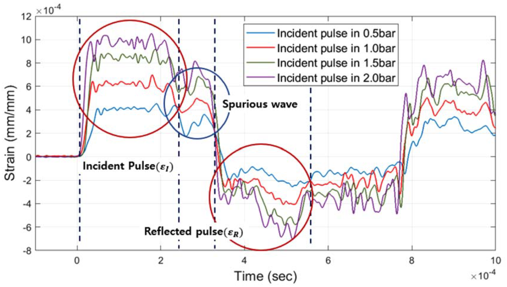
The experiments were performed without specimen and transmitted bar (Figure 4). Thus, incident pulse and reflected pulse can be confirmed only. In experiment results, incident pulses tend to increase as the applied pressure increases. However, it is difficult to judge that reflected pulses were completely acquired after incident pulses were measured. In the SHB theory, if striker bar attacks incident bar without specimen and transmitted bar, incident pulse must be acquired as fully reflected pules. The reflected pulses acquired at 370 mm location may were influenced by the superposition effect of stress wave. Superposition section of stress wave is closely related to the loading duration, and the location where strain gauge is attached must be secured at least the length of striker bar. Since the length of striker bar in initial SHTB model is 530 mm, reflected pulses were overlapped inside loading duration section (Figure 5).

Strain – Time graph from oscilloscope by different pressure conditions at 370 mm strain gauge location.
Strain – Time graph from oscilloscope by different pressure conditions at 800 mm strain gauge location.
Because 800 mm location is outside loading duration section, the reflected pulses must be acquired fully. However, the spurious wave were incidentally acquired after incident pulse were measured at 800 mm. SHTB must be designed to eliminate or avoid spurious wave, and it can be caused by various factor. 17 In other words, the initially designed SHTB had a structural problem in which spurious waves occur, and reflected pulses were measured by superposition of incident pulses and spurious waves. Therefore, in this study, numerical analysis was performed using LS-DYNA, one of the FEM (Finite Element Method) programs, to improve structural problems by eliminating or avoiding spurious waves. Numerical analysis models applied with various conditions were compared with wave forms performed under the 1.0 bar experimental condition result. Factors affecting structural problem were selected as length of striker bar, length of incident bar, and diameter of striker bar and flange.
Results and discussion
FEM using LS-DYNA
To analyze the causes of striker bar, incident bar with flange on the waveform, LS-DYNA, one of FEM programs, was used. For the analysis model, two parts were manufactured with a striker bar and an incident bar with flange, and the values in Table 1 were used to configure the same as the actual model. Figure 6 is FEM modeling of SHTB apparatus. In SHB test, pressure bars should be made of metal with high yield strength material. Pressure bars must act. They should behave only in elastic region to prevent damage for the strain signal due to plastic behavior in repetitive experiment. In initial SHTB model, SNCM439 was used for the material properties of striker bar and incident bar with flange. In LS-DYNA, The Keyword MAT_001_Elastic was used simply because it didn’t exceed yield strength (Table 2).

FEM modeling of SHTB apparatus in LS-DYNA.
Material properties of SNCM439.

The actual striker bar is greatly spaced from the flange because it is accelerated by a pneumatic compression launcher. However, accelerating the striker bar after modeling the pneumatic compression launcher in FEM is inefficient. Rather, only setting a distance between them shortly and imposing the initial velocity just before the collision based on experiments is effective in reducing an analysis time. Also, there is no error from actual experiment. In LS-DYNA, 4.2 m/s, the initial velocity measured in the 1.0 bar experiment, was used. The analysis time was reduced by modeling the distance between striker bar and flange as 1.0 mm. In the case study, analysis models were manufactured according to values of length of striker bar, length of incident bar, and diameter of striker bar & flange under the same initial velocity condition.
Numerical analysis by different length of striker bar
The length of striker bar has an influence on loading duration in SHB theory. Longer length of striker bar, wider initial incident pulse. When acquiring material properties and analyzing stress waves, it is a great advantage to increase loading duration. 21 However, it is difficult to secure a section between incident pulse and reflected pulse. Also, it is hard to avoid superposition of reflected pulse and spurious wave when a spurious wave occurs. To avoid spurious wave and overlap of reflected pulse and spurious wave, the length of striker bar must be reduced compared to initial SHTB model. When striker bar with 300 and 400 mm shorter than initial model was used, it was possible to secure wider sections between incident pulse and reflected pulse than before, but it failed to obtain the fully reflected pulse (Figure 7). Even if a striker bar with 300 mm or less is manufactured, it would be difficult to avoid superposition of waveforms. Therefore, it is impossible to secure the reflected pulse only by changing length of striker bar, and it must be considered together with other factors.
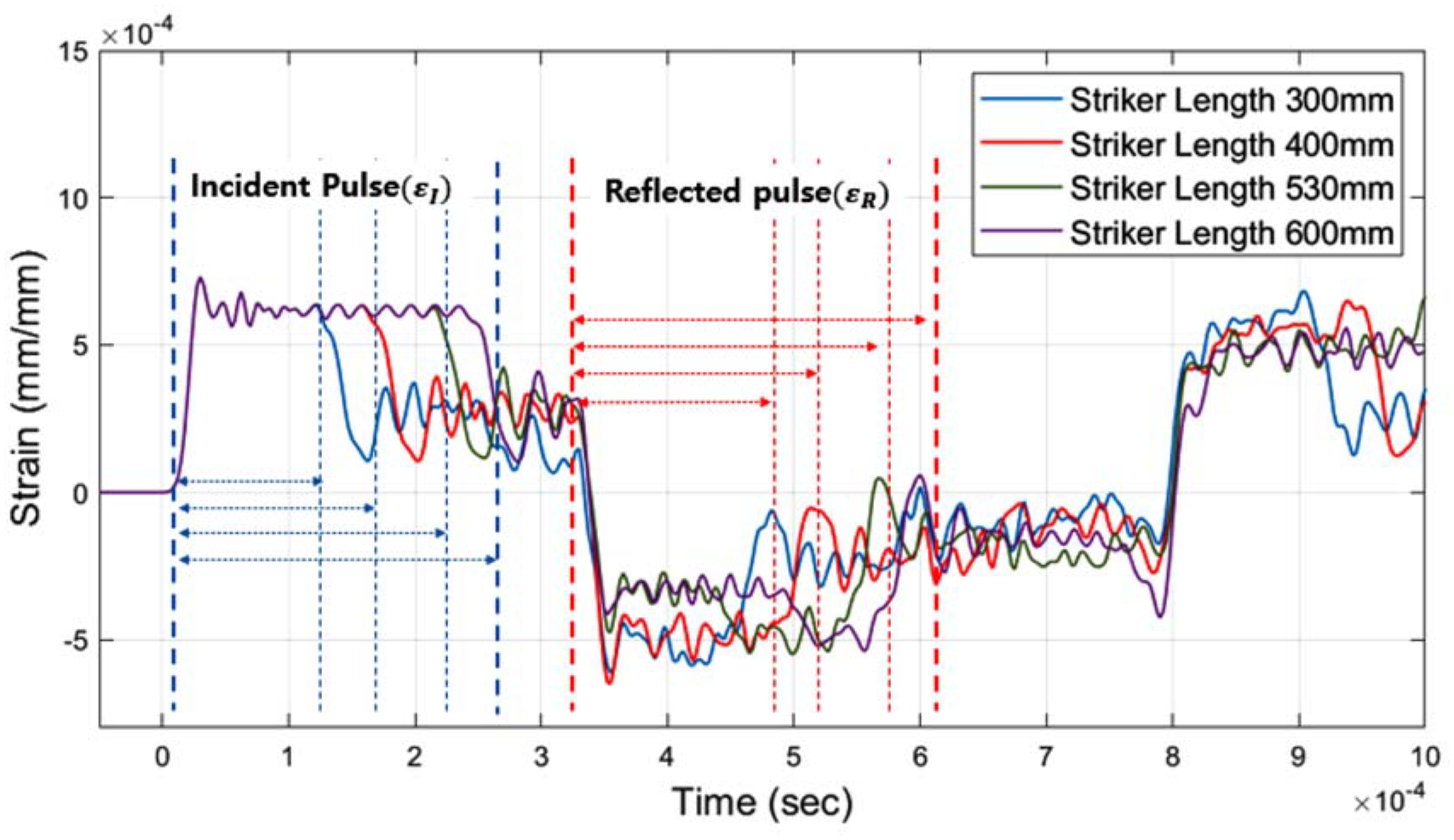
Strain – Time graph from numerical analysis by different length of striker bar in 4.2 m/s condition.
Numerical analysis by different length of incident bar
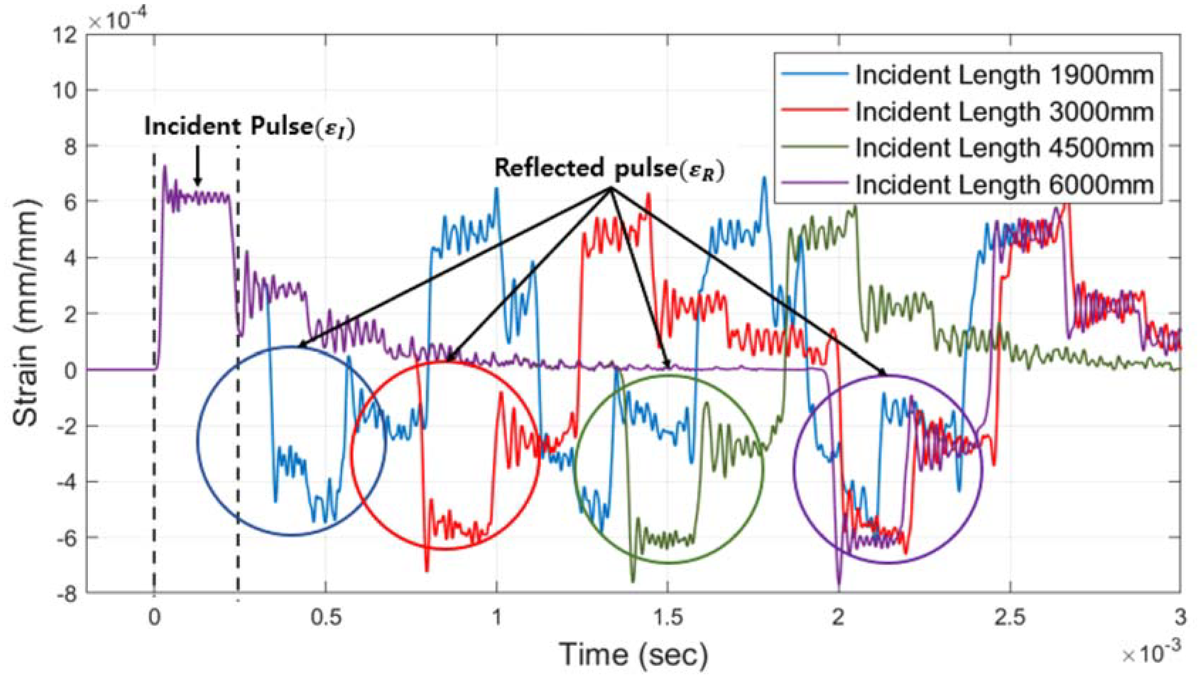
In Section 3.2, as length of striker bar decreased, there was an advantage in securing the section between incident pulse and reflected but all of them failed to avoid spurious wave. Incident bar is an important medium through which stress waves propagate. As length of incident bar increase, overlapping of the damaged waveform and the reflected pulse can be avoided. In 1900mm and 3000mm analysis models, Since length of incident bar was not long enough, superposition of the reflected pulse occurred and the damaged waveform was measured. However, the reflected pulse obtained in 4500 and 6000 mm analysis models had the same shape as the incident pulse (Figures 8 and 9). Their length is meant to be sufficient to avoid overlapping of the waveforms.
Strain – Time graph from numerical analysis by different length of incident bar in 4.2 m/s condition.

Strain – Time graph from numerical analysis of incident bar with 6000 mm in 4.2 m/s condition.
Immediately after the incident pulse was obtained, spurious wave of three-cycle or more were formed. After that, the spurious wave could converge to the zero value, and same waveform as incident pulse could be obtained by avoiding overlap with reflected pulse. According to the previous study conducted by Shin, a spurious wave is formed when multiple impact occurs between two colliding media. 16 Among the causes of multiple impact, the dominant factor is that Stress waves are propagated from high to low impedance medium when a difference in impedance at the interface occurs between two mediums. Impedance is one of the most important keywords in SHB theory. Even if the propagating elastic stress wave passes through the same medium, it is recognized as different impedance when the areas are different. That is, impedance is an index indicating the behavior of a wave when it is propagated and has a great influence on the behavior of a wave when it passes through different media. Since the length of incident bar is independent of impedance, it cannot be a factor to remove spurious wave but it is a factor which can be avoid. Therefore, if it is impossible to change striker bar, it is required to secure the length of incident bar enough to converge the spurious wave. Theoretically, increasing the length is one of the great advantages. However, installing long bars takes up a lot of space in actual. Also, accurate alignment of the central axis in SHB test, where the neutral axis is important, is very challenging during manufacturing.
Numerical analysis by different diameter of striker bar and flange
Spurious wave is formed by multiple impacts that occur when a stress wave propagates from a medium with a high impedance to a medium with a low impedance. The striker bar of initial model was manufactured in the shape of a hollow circle with an inner diameter of 23 mm and an outer diameter of 40 mm, and the incident bar was manufactured in the shape of a solid circle with a diameter of 20 mm. Impedance is
For waveforms with outer diameters of 35 and 40 mm, a spurious wave was obtained between incident pulse and reflected pulse under the influence of multiple impacts, and the fully reflected pulse were not obtained due to overlapping of waveforms. However, in the conditions of 28, 30, and 30.48 mm, the spurious wave were removed and complete reflected pulse wave were obtained because the impedance was low or same between striker bar and incident bar. As diameter decreases, strain signal tends to decrease at same striker bar velocity (4.2 m/s). This is because the initial momentum of striker bar and the propagated stress decrease. 22 In order to remove the spurious wave, striker bar is designed to have a smaller area than the incident bar but designing to have the same area as possible as an advantage in obtaining high stress.
Redesigned SHTB model
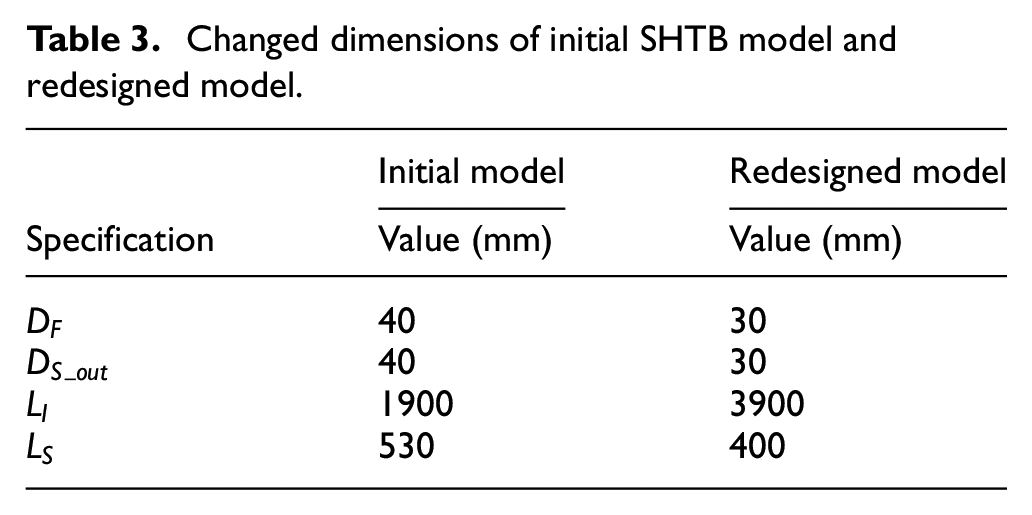
In the previous section, when length of striker bar was reduced, length of incident bar was increased, and out diameter of striker bar and flange were reduced, it was possible to avoid or eliminate the spurious wave. Table 2 shows the values changed during the redesign from initial SHTB model to redesigned SHTB model. First, when the outer diameter of striker bar and flange were theoretically less than 30.48 mm, the spurious wave was removed. However, precision processing in decimal unit is required to produce it according to 30.48 mm in actual work. It is a huge burden in terms of cost. Therefore, a 30 mm outer diameter that can generate a high strain signal based on the results in Figure 10 while removing spurious wave was selected. The length of incident bar is a factor that can avoid overlap with spurious wave, and it has an advantage as length increases. However, considering the relationship with place where the experimental apparatus will be installed, it cannot be increased blindly. The actual model increased the length of incident bar to 3900 mm in consideration of relationship with the place. Instead, the effect was increased by reducing the length of striker bar to 400 mm (Figure 11).

Strain – Time graph from numerical analysis by different diameter of striker bar in 4.2 m/s condition.

Final SHTB apparatus in this study, owned by the Department of Aerospace Engineering at Pusan National University.
To analyze the strain signal obtained in final SHTB model redesigned and manufactured by reflecting the figures in Table 3, it was performed under the same experiment conditions in the initial SHTB model.
Changed dimensions of initial SHTB model and redesigned model.
First, the redesigned strain value is lower than that of the original model under same applied pressure condition. The outer diameter of striker bar was modified from 40 to 30 mm. The length of striker bar was modified from 530 to 400 mm. Striker bar was accelerated by pneumatic compression launcher to just before colliding with flange. At this time, the kinetic energy of striker bar decreased as the weight. The stress and strain signal are affected in proportion to the momentum of the striker bar. The change in momentum according to the weight reduction of the striker bar generates a low strain signal even under the same applied pressure condition. Therefore, it means that the propagated momentum and stress value decreased. Secondly, the shape of incident pulse improved. In original model, a spurious wave occurred immediately after incident pulse. Since length of incident bar was 1900 mm, the spurious wave overlapped with the reflected pulse, and it was impossible to get the same reflected pulse as incident pulse. On the other hand, the reflected pulse was obtained with the same shape as incident pulse in redesigned model. Apart from the comparison with the numerical model, a residual wave was measured immediately after incident pulse. The residual wave converged to zero value after a certain period of time, unlike spurious waves caused by multiple impacts (Figure 9). The cause of residual wave is largely affected by the pneumatic launcher which imposed applied pressure in the striker bar. The numerical model was constructed with a simple striker bar, incident bar with flange and no pneumatic launcher system. However, the actual striker bar is located inside the pneumatic launcher and is fastened with several parts. These serve to push the striker bar in a specific direction using high pressure. In terms of wave’s impedance, they slightly affect the waveform being measured. In other words, removing the residual wave is very challenging and is a part to be solved in the future. However, the initial incident pulse shape formed before the residual wave was measured identical to the analytically predicted result. The reflected pulse was also measured with the same open shape as the incident pulse. The incident bar increased from 1900 to 3900 mm, which was sufficient for the residual wave to converge to zero value. The residual wave didn’t overlap with the reflected pulse. In fact, all the waveforms acquired in the SHB test are not used and data resampling is required. Among them, incident, reflected and transmitted pulse are only sampled, and other data are not used. In Figure 12, the incident and reflected pulse measured from the redesigned model are considered to be resampling and the waveforms are greatly improved compared to the original model.

Strain – Time graph from oscilloscope by different pressure conditions for redesigned model.
Conclusion
In this study, the strain signal was analyzed using the initial SHTB model. A complete reflected pulse was not measured, and a spurious wave was measured. It was impossible to get dynamic material properties. It must be redesigned the initial SHTB model to increase the reliability of material properties acquisition. Factors affecting the spurious wave were determined as length of striker bar, length of incident bar, and diameter of striker bar & flange, and verified using LS-DYNA, one of the FEM.
When length of striker bar was changed, the interval between the incident pulse and the reflected pulse could be widened by adjusting the loading duration. However, it was structurally impossible to avoid the spurious wave. When length of incident bar was changed, the interval between the incident pulse and reflected pulse could be widened while maintain the existing loading duration. If the length of incident bar was sufficiently increased by identifying multiple impact cycles, the overlap of spurious waves could be avoided. When diameter of striker bar & flange was changed, the impedance relationship between striker bar and incident bar was dominant. The spurious wave could be removed by reducing the outer diameter of striker bar.
SHTB was redesigned and manufactured based on the results of FEM. In FEM results, the incident and reflected pulse were completely improved in the striker bar. However, the redesigned model confirmed the residual wave after the incident pulse by a pneumatic launcher and various mechanical components. The overlap of residual wave with reflected pulse was avoided by increasing the length of incident bar, and the waveform was improved than the original model.
In the future work, it is necessary to study the connection between the pneumatic launcher and striker bar and a new launch system to remove the residual wave.
Footnotes
Handling Editor: Chenhui Liang
Declaration of conflicting interests
The author(s) declared no potential conflicts of interest with respect to the research, authorship, and/or publication of this article.
Funding
The author(s) disclosed receipt of the following financial support for the research, authorship, and/or publication of this article: This study was supported by the National Research Foundation of Korea (NRF) grant funded by the Korea government (MSIT) (No. 2019R1A5A6099595) and the BK21 FOUR (Fostering Outstanding Universities for Research) funded by the Ministry of Education (MOE, Korea) and National Research Foundation of Korea (NRF).