
Abstract
This paper deals with an optimal twisting sliding mode controller (OT-SMC) for the operation of a three phase permanent magnet synchronous machine (PMSM) in an electric vehicle (EV). In order to drive these vehicles, optimal performance is needed with robust control against real-time disturbances such as the variable load torque, uncertainties such as the parameters variation and speed variations between medium, low, and high speed as well as good performance characteristics for enhanced drive quality and longer battery time. Several conventional techniques have been applied to PMSM but they suffer from the problem of uncertainties and disturbances due to the PI regulator. A hybrid approach comprising of a robust nonlinear and optimal controller to achieve these objectives is attempted for driving electrical vehicles. This advanced hybrid controller obtained after the merger of sliding mode control (SMC) and a linear quadratic controller (LQR) is found to outperform existing controllers due to their superb performance characteristics. Furthermore, SMC is designed based on the exponential reaching law for the twisting sliding mode control (T-SMC) in order to ensure stability of the system while reducing the chattering, accelerating the rate of convergence with higher accuracy of the control performance, and the LQR is developed using the steady-state error method (N-LQR) in order to obtaining better performance characteristics. In addition, the hybridization between a twisting SMC and an optimal LQR is characterized by stabilizing and minimizing the oscillations in the permanent regime thus optimizing the system’s performance. Extensive simulation results illustrate the effectiveness and validity of the proposed control for achieving the highest performance of the PMSM.
Keywords
Introduction
Electric vehicles whether they are pure or hybrid (PEV/HEV) require electric drives and rechargeable battery backup coupled with robust power electronics and control for their operation. 1 The field of electrical drives is a multi-disciplinary area focused on the transformation of energy from electrical to mechanical form in order to drive an EV as shown in Figure 1. 2 Currently, researchers are aiming to design energy-saving industrial machines with more compact designs, categorized into three classes namely synchronous, asynchronous, and AC motors. In recent times, a significant challenge is found to exist between induction motors and permanent synchronous motors, as PMSMs are increasingly used in industrial applications owing to their higher power density, higher torque to inertia ratio, improved efficiency, low losses, excellent accuracy, simple structure, and strong performance advantages. 3 Besides their significant role in driving electric vehicles (EVs), they are widely used in many other applications such as industrial traction automation, CNC machine tools, industrial robots, aerospace, computer peripherals, electric drives, and other precise position control for servo systems, which demands more power and better performance. 4 However, the control of PMSMs requires enhanced control accuracy with high fidelity and continuous research on new control theories.5–7

Electrical vehicle drive using PMSM.
The control design approaches for PMSMs can be broadly classified into scalar and vector control. Scalar control is easy to implement and provide a relatively steady-state response but it pose the problem of slower dynamics. Therefore, in order to realize a higher accuracy and good dynamic and steady-steady response, closed-loop vector control approach is usually preferred.8,9 The vector control is the largest control group, which includes the conventional and advanced control. The conventional control is dependent on PID regulators like field-oriented control (FOC) and direct torque control (DTC) but these are not robust to the variation of the parameters, variation in torque, and in the speed. To overcome this problem, control engineers have devised some advanced techniques like nonlinear, optimal, predictive, and intelligent control for safety critical applications such as electric vehicles and aerospace.10,11
Nonlinear control consists of various techniques for example, Feedback linearization control (FBLC), sliding mode control (SMC), back-stepping (BSC), passivity-based control (PBC), and improved hybrid techniques such as combining DTC and SMC using wolf optimization algorithm.12,13 In literature, PMSM controllers widely use the FBLC, SMC, and BSC. Whereas, the FBLC control uses the linearization method, SMC or BSC are used for compensating the nonlinearity of the system, and this is what makes them popular for the control of PMSM. 14 The optimal control is dependent on cost minimization such as LQR, LQI, LQG, and others.15–19 Finite-control-set model predictive control (FCS-MPC) and continuous-control-set model predictive control (CCS-MPC) are also popular for fast control of Electric Vehicles.20–22
Nowadays, hybrid control strategy is preferred in the EVs (where PSMS is a design element) due to its good performance and smooth operation for automotive control. Therefore, this paper propose an advanced hybrid control composed of the robust nonlinear and an optimal controller applied to PMSM whereas, the robust nonlinear control is based on twisting sliding mode control (T-SMC), and the optimal control is an LQR variant. Among the most extensive and popular categories of variable structure control, there exists a robust category for both linear and non-linear models to handle parameter variation and disturbances, called the sliding mode control (SMC). This nonlinear robust controller is quite effective in real world scenario and exhibits good performance. Whereas, it depends on the existence, convergence, and stability laws to find a switching surface, which can be realized by the state feedback through an appropriate adjustment of the structure of the control system. The control of a variable structure system by sliding mode usually has two modes of operation, that is, reaching mode (convergence mode) and the sliding mode, that’s because its structure changes during its operation.23–25 Due to the discontinuities applied to the control during the sliding surface, the phenomenon of chattering appears. Since an ideal sliding surface requires control that can switch with infinite frequency, this phenomenon appears around the sliding surface in the form of frequent and excessive oscillations due to the highly discontinuous nature of the signum function. Thus, the performance of the system is compromised, and this makes it a serious barrier to sliding mode control applications. Significant research effort has been directed to eliminate or at least reduce these undesirable effects, for example, replacing the signum function by a function characterized by a composite saturation function with one or two thresholds. Even this approach is not much effective. This is why, in this paper, we propose a twisting sliding mode control with the development of a switching law based on the tangent hyperbolic function.26–28
The second controller based on linear-quadratic controller (LQR) is an optimal controller, which can be applied to a large range of MIMO systems. It is characterized by a quadratic cost function that provides the control designer ample freedom to compromise among various performance criteria. The goal of the LQR control is to minimize the energy and optimize the performance of the system. 29 The rest of this paper is organized as follows: Section “Mathematical modeling of PMSM” describes the mathematical modeling of the PMSM. The design of the twisting sliding mode control for the speed loop of the PMSM is described in Section “Design of a sliding mode controller for speed loop.” Whereas, in Section “N-LQR control based on field oriented compensation of PMSM,” the LQR regulation/tracking based on the field-oriented control (FOC) is applied on the current loop of the PMSM. In Section “Simulation results and discussion,” the detailed simulation results and discussion is covered followed by the conclusion, which is presented in the last section.
Mathematical modeling of PMSM
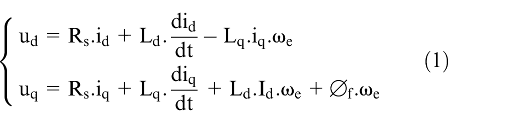
PMSM works analogous to a three-phase induction machine. A rotating magnetic flux is produced by the three-phase voltage source connected to the stator windings. The poles of the PMSM are equal between the stator and rotor as the rotor is a magnet; therefore, the rotor flux is considered constant, which contributes to reducing brush and rotor losses because it cancels the need for the source to provide an excitation current. 30 The voltage imposed on the machines can be expressed in the d-q frame using the motor torque as given in equations (1) and (2) respectively31,32:

There are several methods used to model and simulate the PMSM dynamics as explained in the following sub-section.
Transfer function representation
Based on the PMSM model represented in equation (1), the decoupling between the linear model of PMSM and the disturbances is used to find the transfer function of the PMSM model. 33 Furthermore, the linear model is designed by using the internal and external model. Where, the first one represents the current loop equations and the second one depicts the speed loop equations after the linearization of the nonlinear electromagnetic equations of PMSM as represented in equation (2). Consequently, the internal and external linear model of the PMSM mentioned above is designed as follow:

The disturbances are split into the internal and external disturbances. The first one is a non-linear expression, which is calculated by the difference between the nonlinear model represented in equation (1) and the internal model shown in equation (2). The second one is a linear expression and it is obtained by the load torque applied on the PMSM drive. The disturbances mentioned above are formulated as follow:

Using the equation (3), the transfer function of the internal and external linear model is as follows:

Where,
Linear state-space method (LSSM)
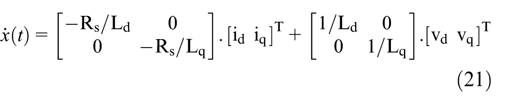
Here, we use the linear state-space representation for both linear internal and external model of PMSM represented in equation (3) to describe the system as equation (6). This method is similar to the first method on the part of the decoupling to the linear model from the disturbances, but differs with it in terms of temporal or frequency variables, as this method depends on the temporal variable as follows:

Where the disturbances are modeled as follow:

Nonlinear approach
In this representation, we use the following nonlinear equations to represent the dynamics of PMSM 34 :

Where:

Design of a sliding mode controller for speed loop
Sliding mode (SMC) is one of the powerful variable structure nonlinear control techniques that can change structure and switch between two values according to a very specific switching logic S(x), applied to non-linear systems comprising of multiple fields like PMSM. It is robust to the variation of parameters, with special characteristics such as strong interference suppression and good dynamic performance, which means it can produce a robust closed-loop system under system uncertainties and external disturbances.35–37 This controller design is carried out in two steps: convergence toward the surface and then sliding along it, to force the system to reach a certain surface called the sliding surface and stay there until equilibrium.38,39 In this paper, the switching law is developed based on SMC and a speed control loop is designed accordingly.
To apply the SMC on the speed loop, three-step tracking control is designed which is as follows12,40:
Choice of the sliding surface
The general formula of the sliding surface is determined according to the order of the system as follows 41 :
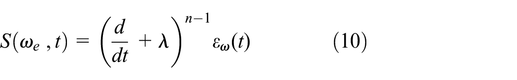
Where

Determination of sliding conditions
The investigation of the existence of the sliding mode based on the Lyapunov method consists in establishing a scalar function L(x) defined positively for every output “y” and designing a control law according to this function such that its derivative decreases, hence assuring the stability of the system, which mathematically can be expressed as following 42 :

The condition represented in equation (12) guarantees only approximate sliding surface convergence. Therefore, for convergence in finite time, it is replaced by a more restrictive condition called

where
There are generally three steps called switching mode or reaching mode (RM), sliding mode (SM), and the steady-state mode (SS), over which, the control systems of variable structure operate. These three steps are illustrated in the Figure 2 below 43 :
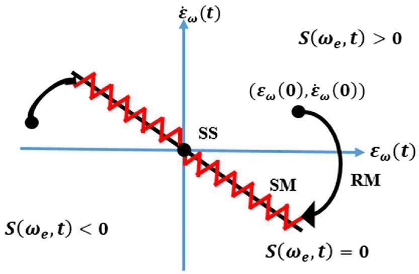
System trajectory on the phase plane.
Calculation of T-SMC law
The control law of SMC is designed in two stages; the first is called the approaching phase, which refers to the trajectories of the system pointing to the sliding surface S = 0, and the second is called the sliding phase, which maintains these trajectories on this surface. Using these two phases and satisfying the reachability conditions of the surface S(x), the control law is structured into two components. One of these two is continuous and related to the precise control and allows support and slip along the surface, called equivalent term

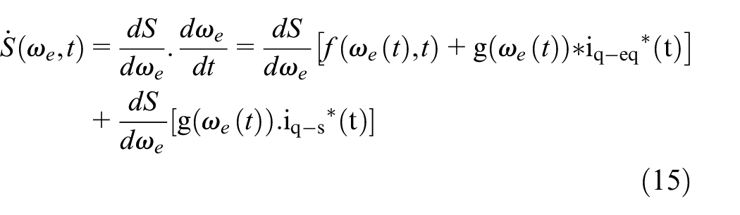
Depending on the sliding surface equation and the control law shown in equations (11) and (14) respectively, the sliding surface derivative can be given as:
During the sliding phase,

In the approaching phase, where
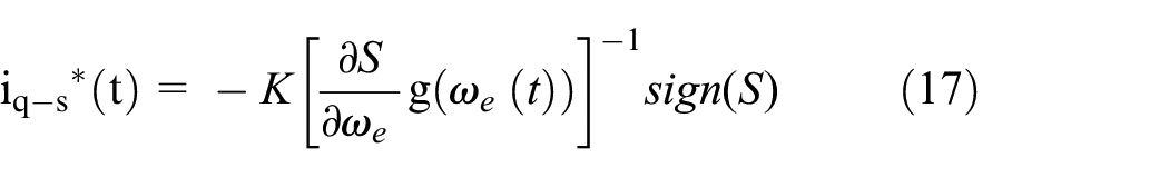
Where “K” is a positive constant and “sign” is the signum function defined by:

There are system discontinuities in our control loop such as switching delay or actuator limitation during the sliding system, which can switch at an infinite frequency as per the ideal sliding regime. This abrupt response leads to the chattering phenomenon, which forms oscillations around the sliding surface of the system trajectories.
As this phenomenon is harmful to the control unit and leads to the deterioration of accuracy control, which causes overheating of electrical systems and premature deterioration of mechanical systems. To reduce this phenomenon, an interesting approach has been proposed by Gao et Hung, 44 in which the dynamic adaptation of the control component according to the change of the sliding function is proposed. Since, it adopts a non-linear convergence design, for reducing the high-frequency steady-state switching, without affecting the system error or the convergence time. 45 By exploiting this proposed approach and replacing the signum function with a continuous approximation, called hyperbolic tangent, the switching law-based T-SMC becomes as follows:

where
The scheme of a speed control loop based on the proposed SMC is expressed in Figure 3.

Scheme of speed loop based on proposed T-SMC.
N-LQR control based on field oriented compensation of PMSM
In order to meet the objectives of the conventional control like field-oriented control (FOC), the LQR control is proposed for the current loop of the PMSM. Furthermore, the tracking error of the direct and quadratic current is chosen as the state variable, for assessment of the system’s performance and minimizing the steady-state error.
Design of the internal linear model based on tracking error dynamics
The state-space model is based on the tracking error, which is represented in equation (3) as:

where;
The full state internal linear model of PMSM has been described. Now, its output equation can be written as under:

In addition, the tracking error is represented in the equation (23):

From the equations (21) and (23), we have:

Where “I” is the identity matrix. The goal of the design of the state-space model based on tracking error is to force the steady-state error to zero and to make the system tracking asymptotically stable, this means

The reference vector is the step vector, which means that:

Finally, the error dynamics are obtained by subtracting state and error values at (

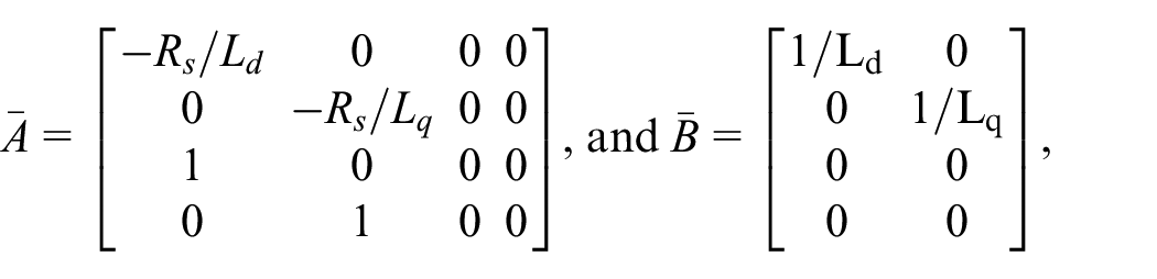
We put:

Where,
In order to track a constant reference, the output y(t) should reach r(t) and the state derivative should reach to zero in finite time as follows:

From equations (27) and (28), we have:

After that, the error vector is represented as:

From the equations (30) and (31), the error dynamics in generalized form are as follows:

Where:
It is evident that the control law for the error dynamics represented in equation (32) as:

However, from equations (32) and (33), the closed-loop error dynamics are as follows:

Controllability of the error dynamics
Before applying a control based on a state-space model, the controllability of the state-space must be studied. Therefore, if the rank (r) is equal to the system’s order that is, degree (n), then the state-space model is controllable. The controllability matrix is obtained by equation (35). 46

Since, the error dynamics presented in equation (31) is a fourth-order; therefore, the controllability matrix is depicted as follows:

Hence,

It is straightforward to demonstrate that the rank of Pc is 4, which is the same as the order of the system in equation (31). This indicates clearly that the error dynamics of equation (31) are always controllable for input values of

Current decoupling model of the PMSM based on optimal LQR control.
Analysis of LQR control with integral action based on full state feedback
The linear quadratic regulator (LQR) based on optimal control provides a systematic method of designing a control law for optimal performance of the linear multivariable systems. It is based on the principle that a feedback gain matrix is calculated through the cost function represented in equation (34) to render the MIMO’s error dynamics asymptotically stable by the Q matrix while minimizing the expenditure of energy of the control signals by the R matrix.10,47

where R and Q are both positive definite matrix.
The feedback control law for the internal linear model is expressed in equation (39) as:

where “P” is a positive-definite matrix and is the solution of the reduced-matrix Riccati equation is represented below:

Where: u(t) =
Simulation results and discussion
The hybrid control strategy for the control of PMSM in an electric vehicle (EV) is proposed in this article. A robust T-SMC controller is applied to the speed control loop and the optimal LQR control is used for the internal linear model of the PMSM’s current loop. Thus, the objective of this design framework is to test the PMSM performance and ensure a robust control under parameter variation, disturbances, and variation of PMSM’s speed reference in order to verify the performance. The contribution of this research is thoroughly verified in the simulation as per the design framework shown in Figure 5, which establishes its efficacy by using Matlab/Simulink platform. Moreover, some reference scenarios are specifically designed for the validity of the control algorithm.
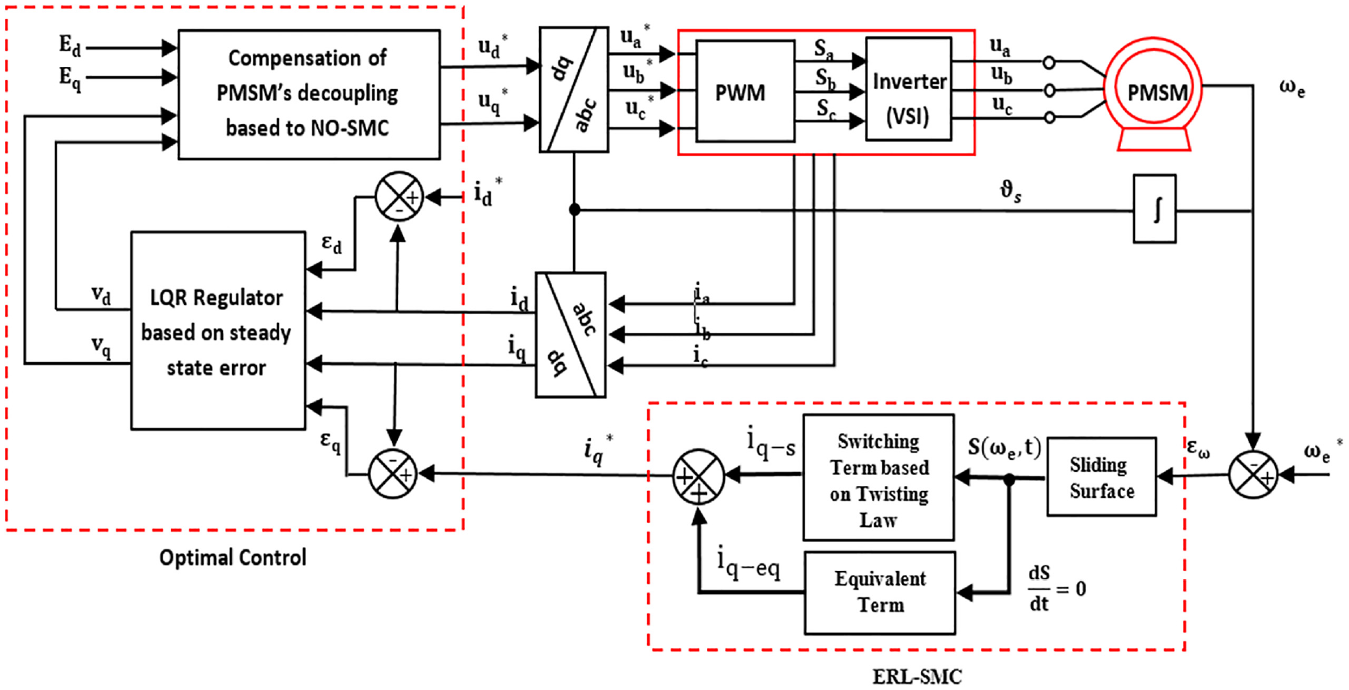
Scheme of PMSM’s control based on OT-SMC.
This study simulates three important aspects of the EV operation, which play a fundamental role in the PMSM control performance characteristics, and studies the robustness to both disturbances effect and parameter uncertainties as they occur in real life. In summary, four scenarios are presented to demonstrate the effectiveness of the proposed control. The first scenario examines the most important aspect of the PMSM control, that is, tracking control of speed commands. The reference speed is varied from the low speed (20 rad/s), medium speed (80 rad/s), high speed (300 rad/s), and a complete stop (0 rad/s) with load torque applied from 5 to 10 N m during 0.5 s.
Furthermore, the variation of the load should not affect the performance of the PMSM’s speed significantly, as seen from the performance characteristics resulting in overshoot and undershoot on the speed levels.
In addition, regarding the rest of the characteristics, the proposed control strategy shows excellent results. In terms of the time response characteristics, the results show that the settling time is very small (~5 ms) during both the zero speed and low-speed, it is around 3 ms during the medium speed and 2 ms during the high-speed operation. The steady-state error is almost non-existent whereas, the estimated overshoot is 0.5% during the low speed. Figure 6 illustrates the validity of these scenarios.

First scenario: Reference speed control performance: (a) Speed variation, (b) Torque, (c) d-q currents, and (d) abc currents.
In order to prove the robustness of the proposed control under the disturbance effect, the load torque is varied between 0 and 5 N m at different time instants. Figure 7 shows the simulation results for the PMSM’s performance, where the robustness of the controller is proven by the minimal undershoot or overshoot which is projected at 0.15% of the peak value in Figure 7(a) and (b). Moreover, regarding the tolerance band of the direct and quadratic current, it is estimated as a negligible value as shown by the performance curves of the currents in Figure 7(c) and (d).

Second scenario: Effect of load torque on speed control: (a) Speed following, (b) Torque variation, (c) d-q currents, and (d) abc currents.
The third scenario studies the robustness of the controller against the parameter variation, where the PMSM model parameters (

Third scenario: Robustness against the parameter variation: (a) Speed following with parametric uncertainty, (b) Torques, and (c) d-q currents.
To summarize the results of the proposed control scheme, and to highlight the contribution of this paper, a comparative study is presented for the proposed controller that is, novel optimal twisting SMC (OT-SMC), Twisting SMC with exponential reaching law (T-SMC), and classical SMC (C-SMC). The comparative results of the three controllers are shown in Figure 9. The simulation plots depicts that the proposed control scheme works well as compared to the T-SMC and C-SMC, where it ensures the advantage and efficiency through the optimal performance characteristics. The comparative results of Figure 9(a) and (b) are numerically expressed in Table 1, which shows a small steady-state error (SSE) and settling time for T-SMC as compared to C-SMC.

Performance comparison of three controllers (OT-SMC, T-SMC, and C-SMC): (a) Speed variation and (b) Load torque variation.
Control performance comparison of the three schemes.
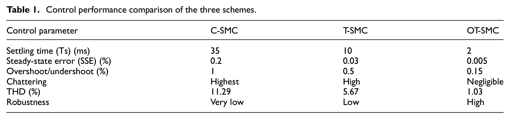
As observed, OT-SMC outperforms the two controllers by showing the lowest settling time and SSE in addition to the robustness to the changing parameters and variable load torque. Furthermore, the harmonic analysis of the current of the three controllers (OT-SMC, T-SMC, and C-SMC) that shown in Figure 10 illustrates the advantage of the proposed controller as it results in the lowest value of total harmonic distortion (THD) as compared to the T-SMC and C-SMC respectively. A comprehensive comparison of these three control schemes are presented in Table 1 to demonstrate the advantage of the proposed control in this paper. The simulation parameters of PMSM include

Harmonic analysis of the current of three controllers: (a) OT-SMC (b) T-SMC (c) C-SMC.
Conclusion
This paper presents a hybrid controller scheme for the control of the PMSM to drive an Electric Vehicle stably and effectively under varying operating conditions. The prime objective is to improve the performance of the PMSM in the presence of real-world disturbances and modeling uncertainties. The Twisting SMC (T-SMC) is applied on the speed loop, which gives the reference quadratic current with excellent performance characteristics. After that, the LQR optimal controller is used as an internal linear model of the current loop of the PMSM. Moreover, the error dynamics are added as the state variable, which contributes in enhancing the accuracy of the optimal control performance. Finally, simulation results demonstrated the validity and feasibility of this contribution for good performance and robust control of an electric vehicle offering least settling time, steady state error, overshoot and chattering as compared to T-SMC and C-SMC controllers. In future, further research will be conducted for the realization of a hardware in loop (HIL) setup of PMSM drive for use in high-performance EVs.
Footnotes
Appendix
List of symbols
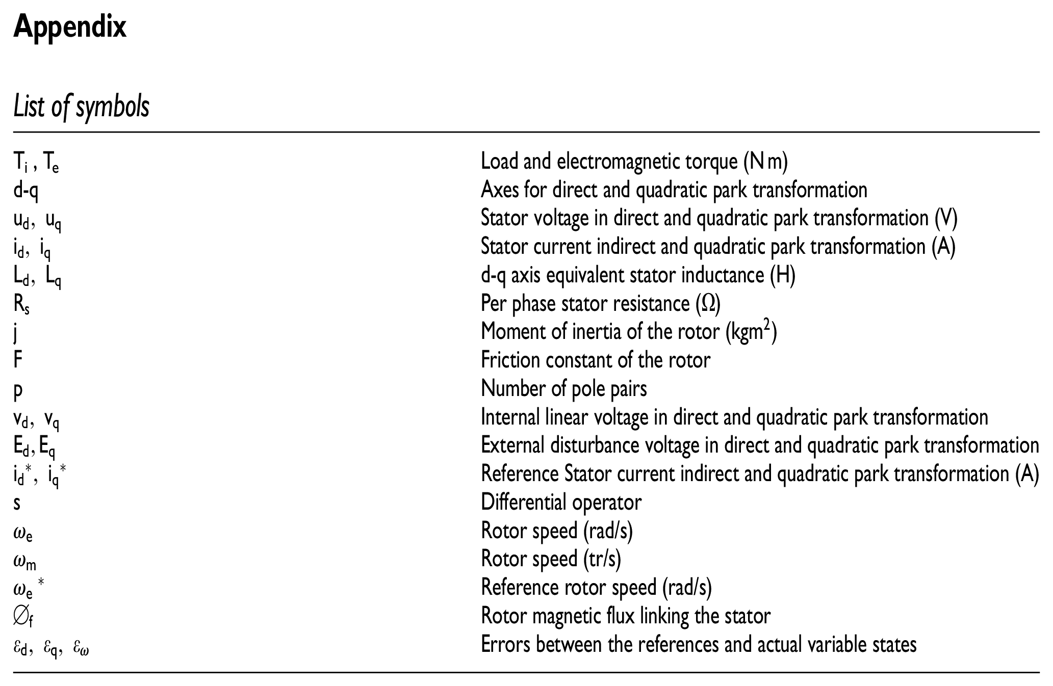
| Ti, Te | Load and electromagnetic torque (N m) |
| d-q | Axes for direct and quadratic park transformation |
| Stator voltage in direct and quadratic park transformation (V) | |
| Stator current indirect and quadratic park transformation (A) | |
| d-q axis equivalent stator inductance (H) | |
| Per phase stator resistance ( ) | |
| Moment of inertia of the rotor ( ) | |
| Friction constant of the rotor | |
| Number of pole pairs | |
| Internal linear voltage in direct and quadratic park transformation | |
| External disturbance voltage in direct and quadratic park transformation | |
| Reference Stator current indirect and quadratic park transformation (A) | |
| s | Differential operator |
| Rotor speed (rad/s) | |
| Rotor speed (tr/s) | |
| Reference rotor speed (rad/s) | |
| Rotor magnetic flux linking the stator | |
| Errors between the references and actual variable states |
Handling Editor: Chenhui Liang
Authors’ Note
Zeashan Hameed Khan is now affiliated to Interdisciplinary Research Center for Intelligent Manufacturing & Robotics (IRC-IMR), King Fahd University of Petroleum and Minerals (KFUPM), Saudi Arabia.
Declaration of conflicting interests
The author(s) declared no potential conflicts of interest with respect to the research, authorship, and/or publication of this article.
Funding
The author(s) received no financial support for the research, authorship, and/or publication of this article.