
Abstract
Jet nozzle is a core component of the hydraulic perforating fracturing tool, and the design of the nozzle structure directly affects the perforating effectiveness and efficiency. In this paper, the flow field characteristics of hydraulic perforating nozzles are calculated by the SST k-ω turbulence model. The results show that the nozzle structure parameters significantly influence the jet performance. Through orthogonal experiments, the conical-cylindrical nozzle geometric parameters are preliminarily optimized as follows: the cylindrical segment diameter is 6 mm, the contraction angle is 10°, the contraction segment length is 8 mm, and the cylindrical segment length is 12 mm. The results can provide theoretical guidance for later experimental research on jet rock breaking and optimization design of the jet tools.
Introduction
Natural gas hydrate is the most valuable submarine mineral resource known so far. Its huge resource volume and attractive development and utilization prospects make it highly likely to become an alternative energy source for coal, oil, and natural gas in the 21st century. It is a strategic commanding point for future global energy development.1,2 The ultimate aim of researching and conducting trial extractions of gas hydrates is to achieve industrial-scale development. Enhancing the efficiency of gas hydrate reserve utilization and improving the development rate are inevitable challenges that must be tackled for the industrial development of gas hydrates. To enhance the gas production rate of individual wells, prolong the life cycle of production wells, and achieve the commercial development of natural gas hydrates, it is urgently necessary to carry out research and development on the technical support for the improvement of gas hydrate reservoirs and the testing technology for increased production.3,4 Providing technical support for increased production, stable production, and efficient development of natural gas hydrate reservoirs. 5 It is of great strategic significance for developing hydrate exploitation technologies and realizing commercial product.
Reservoir modification and production enhancement technology, especially hydraulic fracturing technology, is crucial to efficiently develop tight and low permeability oil and gas resources.6,7 This technology has been extensively tested through production practices, especially in the development of unconventional resources such as shale oil and gas and tight oil and gas, playing a crucial role.8,9 This provides a valuable reference for the product enhancement and stimulation of natural gas hydrate reservoirs. In the early 1990s, the concept of directional perforation and completion was proposed from the rock mechanics perspective, which suggested that selecting the appropriate perforation direction could control the hydraulic fracture morphology and reduce the fracture pressure. In the late 1990s, researchers studied the directional perforation technology for high-permeability and weakly consolidated formations during hydraulic fracturing operations. They developed a new directional perforation system and successfully applied it in the oil-well field. Since the beginning of this century, Schlumberger has completed the OriendXact pipeline delivery and cable directional perforation system. The technology is mainly applied in controlling sand production in oil and gas wells and hydraulic fracturing modification and has achieved effective results.10–12
During the on-site hydraulic fracturing process, it is often difficult to initiate fractures due to the plastic deformation of hydrate reservoirs, necessitating directional perforation techniques to create fractures. 13 However, existing directional perforation tools for unconventional reservoirs are mainly designed for 4-1/2″, 5″, and 7″ casing wells, and are not suitable for large-sized 9-5/8″ casing wells in in natural gas hydrate. Moreover, conventional hydraulic perforation tools are plagued by issues such as severe wear of nozzles, and low tool longevity.14,15
Hydraulic sandblasting perforation is an essential aspect of the hydraulic fracturing process and the nozzle is the core component of a hydraulic sandblasting perforation tool. Its structure determines the wear resistance and jet performance of the nozzles, which can affect the penetration depth and rock-crushing volume of hydraulic sandblasting perforation, thereby affecting the perforation efficiency. The nozzle is the core component of the hydraulic perforation tool, and its structure determines the wear resistance and the jet performance of the nozzle. It also affects the penetration depth and rock-crushing volume of hydraulic perforation, thereby affecting the perforation effect. 16 The conical-cylindrical nozzle is widely used in hydraulic sandblasting perforation operations. Still, it incurs significant energy loss and results in a low fluid energy conversion rate, limiting the maximum depth achievable for hydraulic sandblasting perforation. 17 Scholars have utilized numerical simulation methods to explore the jet performance of small-diameter nozzles.18,19 Xu and Li 20 conducted a comparative analysis of the jet performance of conical, streamlined, isotropic, and elliptical nozzles through numerical simulation. The results indicated that the isotropic nozzle has the longest jet iso-velocity core. Wen et al. 21 analyzed the hydraulic performance of typical straight conical nozzles with different structures. They found that the impact force of the water jet produced increased significantly with the increase of its outlet diameter.
The optimization of the internal flow channel shape of the nozzle has a significant impact on its jet performance, and the optimal structural parameters of the nozzle are significantly influenced by operating conditions. Therefore, it is necessary to analyze the influence of nozzle parameters on jet performance under the conditions of natural gas hydrate reservoir perforation operations and prefer high-performance nozzle structures accordingly. This study selects the conical-cylindrical nozzle as the research object due to its low processing cost and better jet performance. The CFD is used to conduct numerical simulations of the nozzle jet flow characteristics. The structural parameters of the nozzle are optimized using the two evaluation indicators of nozzle pressure loss and jet impact force. The research results have important guiding significance for the structural optimization of hydraulic perforation nozzles.
Numerical simulation method
Physical model
Figure 1 shows the two-dimensional axisymmetric model of the jet flow field of the conical-cylindrical nozzle, which is used to calculate the internal and external flow field characteristics. Four factors significantly affect the jet performance of the conical-cylindrical nozzle: contraction angle, contraction segment length, cylindrical segment length, and cylindrical segment diameter.

Physical model of nozzle jet flow field and schematic diagram of conical-cylindrical nozzle geometric parameters.
Grid mesh
Grid meshing is a critical step in numerical simulation. High-quality grids must be used as the basis to obtain high-precision calculation results. In order to simulate a flow problem accurately, the appropriate grid needs to be meshed based on the practical problem. 22 The nozzle wall is refined with a boundary layer to improve the calculation accuracy. In this paper, the appropriate meshing strategy is determined by grid independence analysis, and the computational domain is divided into 137,527 grid cells. The calculation model of the jet flow field is meshed using a quadrilateral grid, as shown in Figure 2.

Computational grid of nozzle jet flow field.
Turbulence model
Currently, there are many turbulence models, but each model has certain limitations and application conditions. 23 By comparing the commonly used k-ε and k-ω models and performing multiple calculations, it is found that the SST k-ω model has better accuracy and algorithm stability than the k-ε model in the near-wall region and has high accuracy in simulating separated flows.24,25 The SST k-ω model has advantages in predicting near-wall and vortex flow and is suitable for boundary layer flow, separation, and transition in adverse pressure gradients. 26 Therefore, the SST k-ω model can better handle wall-confined flows with high strain rates and large curvature of streamlines. In this paper, the SST k-ω turbulence model is adopted to solve the turbulence field of the nozzle. The basic control equations are:


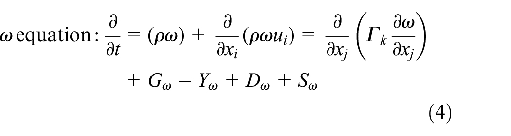
where i, j are coordinate direction and the direction of the velocity components, respectively; ui, uj are the speed of different coordinate directions, respectively; ρ is the water density; μ is dynamic viscosity;
Boundary conditions and parameter settings
In order to compare the hydraulic characteristics of nozzles jet with different geometric parameters and exclude the effect of other factors on the simulation results, simulation calculations using the same set of parameters, specific to:
(1) Inlet is velocity-inlet; outlet is pressure-out; model surface is wall without slip solid wall; x-axis is set as axisymmetric boundary condition; the initial turbulence intensity at the inlet and outlet can be solved by the following empirical formula:

(2) The fluid medium is water, which is an incompressible and stable flow;
(3) The discrete format is SMIPLEC, the momentum equation and turbulent kinetic energy are measured using second-order accuracy upwind scheme to ensure accuracy and stability;
(4) The continuity residual is set to 1 × 10⁻⁵, and others are set to 1 × 10⁻⁶.
Results and discussion
Analysis of flow field characteristics
Under the condition of jet flow rate Q = 0.33 m3/min, the flow field characteristics of the nozzle with geometric parameters of θ = 30°, D = 6 mm, L1 = 8 mm, L2 = 12 mm are investigated.
Velocity distribution
Figures 3 and 4 respectively present the velocity contour and velocity vector of the nozzle jet flow field, revealing that the flow velocity is greatest in the cylindrical section of the nozzle. As the jet exits the nozzle, it experiences shear forces with the external fluid, leading to a gradual decrease in the radius of the jet iso-velocity core. The maximum velocity of the jet is 223 mm/s, located at the junction between the contraction section and the cylindrical section, where the nozzle diameter reaches its minimum value.

Flow field velocity contour.

Flow field velocity vector.
Pressure distribution
Figure 5 displays the static pressure contour of the nozzle jet flow field, indicating that the pressure begins to decrease from the contraction section of the nozzle. At the same time, there is a local high pressure at the center of the jet striking surface. The greater the pressure at this point, the higher the rock-breaking efficiency of the jet.
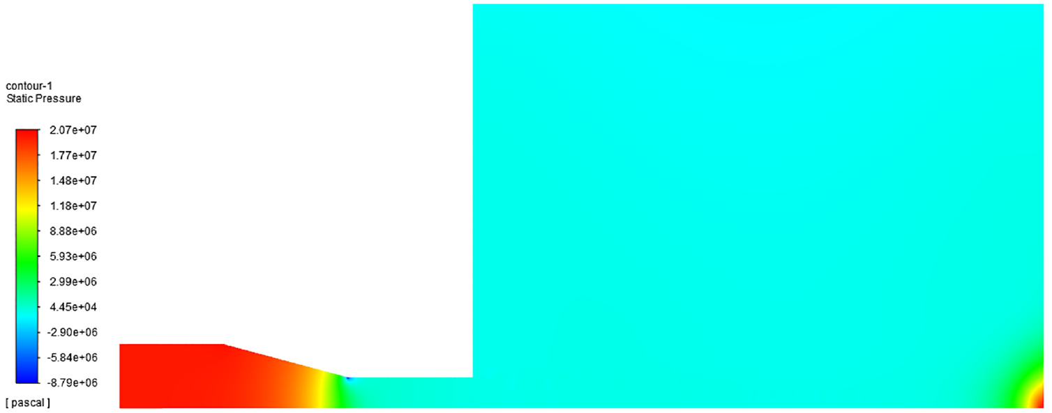
Flow field pressure contour.
Effect of jet flow rate
In the numerical simulation, the geometric parameters of the nozzle (D = 6 mm, θ = 10°, L1 = 8 mm, L2 = 12 mm) are kept unchanged, and the influence of jet flow rate on the nozzle jet performance is analyzed. The effect of flow rate on the jet performance is obtained, as shown in Figure 6. Figure 6(a) illustrates the variation of the maximum jet velocity and pressure loss of the nozzles with different jet flow rate. It is evident that the maximum jet velocity linearly increases with the flow rate. As the jet velocity increases, the viscous drag and pressure drag experienced by the flow through the nozzle also increase, resulting in an increase in the pressure loss of the nozzle. In hydraulic perforation operations, it is necessary to select low-pressure drop nozzles while considering the allowable pumping pressure of the equipment under the premise that the jet velocity meets the rock-breaking conditions.

Effect of flow rate on the jet performance: (a) variation law of maximum velocity and nozzle pressure loss, (b) velocity distribution along the nozzle axis, and (c) impact pressure distribution law.
Figure 6(b) shows the axial velocity distribution curve of nozzles with different flow rate. It is apparent that the jet gradually accelerates inside the nozzle and maintains its velocity after exiting the nozzle. Furthermore, the length of the jet iso-velocity core is essentially consistent across various flow rate. Figure 6(c) presents the curve of the wall impingement pressure distribution for different jet flow rate, revealing that the maximum impact force occurs at the center of the jet and increases with the jet flow rate. For nozzles with the same structure, a larger flow rate results in a greater kinetic energy of the jet, leading to a deeper and wider perforation hole.
Effect of conical-cylindrical nozzle geometric parameters
The nozzle geometric parameters significantly affect the rock-breaking performance and energy consumption of the jet. Reasonable geometric parameter design is the key to achieving low energy consumption and efficient perforation. This study first uses a single-factor analysis method to investigate the effects of different nozzle geometric parameters on pressure loss, velocity distribution, and pressure distribution of the jet flow field. Then, combining with the orthogonal experimental method, the optimal geometric parameters of the conical-cylindrical nozzle are determined, providing theoretical guidance for the structural design of the nozzle.
Cylindrical segment diameter
Firstly, keeping other parameters constant in the numerical simulations (Q = 0.33 m3/min, θ = 10°, L1 = 8 mm, L2 = 12 mm), the influence of different cylindrical segment diameters on the jet performance is analyzed. The effect of cylindrical segment diameter on the jet performance is obtained, as shown in Figure 7. Figure 7(a) shows the variation of the maximum jet velocity and pressure loss of the nozzles with different cylindrical segment diameters. With the constant jet flow rate, as the cylindrical segment diameter increases, the maximum velocity of the jet and the pressure loss gradually decrease. Excessive pressure loss not only consumes excessive energy but also poses significant safety hazards to fracturing operations. Meanwhile, there is a threshold of jet velocity for rock-breaking, and the higher the jet velocity, the higher the rock-breaking efficiency. Considering all factors, it is preliminarily determined that the cylindrical segment diameter is 6 mm, and the corresponding jet velocity and pressure loss can meet the requirements for perforation operations. Figure 7(b) and (c) show the effect of the cylindrical segment diameter on the velocity distribution along the nozzle axis and the radial pressure distribution on the jet impact wall, respectively. Under the condition of a constant jet flow rate, the smaller the diameter of the nozzle, the higher the jet velocity, resulting in a greater impact force on the wall.

Effect of cylindrical segment diameter on the jet performance: (a) variation law of maximum velocity and nozzle pressure loss, (b) velocity distribution along the nozzle axis, and (c) impact pressure distribution law.
Contraction angle
Similarly, keeping other parameters constant in the numerical simulations (Q = 0.33 m3/min, D = 6 mm, L1 = 8 mm, L2 = 12 mm), the influence of different contraction angles on the jet performance is analyzed. The effect of contraction angle on the jet performance is obtained, as shown in Figure 8. Figure 8(a) shows the variation of the maximum jet velocity and pressure loss of the nozzles with different contraction angles. It can be observed that the maximum jet velocity and the nozzle pressure loss both increase with increasing contraction angle. This is because the larger the contraction angle, the larger the windward area of the jet flowing through the nozzle contraction section, and the greater the pressure drag that the jet experiences. To pass through the same flow rate, a greater pressure loss is required. Besides, the larger the contraction angle, the greater the internal diameter change rate at the junction of the nozzle contraction section and the cylindrical section, and the maximum jet velocity also increase accordingly.

Effect of contraction angle on the jet performance: (a) variation law of maximum velocity and pressure loss, (b) velocity distribution along the nozzle axis, and (c) impact pressure distribution law.
Figure 8(b) shows the axial velocity distribution curves of the jet corresponding to different contraction angles, and it can be seen that the jet iso-velocity core is the same for different nozzle contraction angles. Figure 8(c) shows the wall impact pressure distribution curves corresponding to different contraction angles, revealing that the contraction angle has little effect on the maximum impact pressure. In other words, the nozzle contraction angle has little effect on the rock-breaking efficiency of the jet. Therefore, in perforation operations, the nozzle with a contraction angle of 10° is preferred to reduce the pressure loss.
Contraction segment length
Then, keeping other parameters constant in the numerical simulations (Q = 0.33 m3/min, θ = 10°, D = 6 mm, L2 = 12 mm), the influence of different contraction segment lengths on the jet performance is analyzed. The effect of contraction segment length on the jet performance is obtained, as shown in Figure 9. Figure 9(a) shows the variation of the maximum jet velocity and pressure loss of the nozzles with different contraction segment lengths. The maximum jet velocity is not affected by the contraction segment length. With the increase of the contraction segment length, the pressure drag and viscous drag experienced increase, resulting in a gradual rise in nozzle pressure loss. Figure 9(b) and (c) show the effect of the contraction segment length on the velocity distribution along the nozzle axis and the radial pressure distribution on the jet impact wall, respectively. Under the constant jet flow rate condition, the contraction segment length has no effect on the jet iso-velocity core, and the corresponding maximum impact force of the jet has basically no change. Besides, the nozzles with a contraction segment length of 6 and 8 mm have the largest jet perforation hole.

Effect of contraction segment length on the jet performance: (a) variation law of maximum velocity and nozzle pressure loss, (b) velocity distribution along the nozzle axis, and (c) impact pressure distribution law.
Cylindrical segment length
Finally, keeping other parameters constant in the numerical simulations (Q = 0.33 m3/min, θ = 10°, D = 6 mm, L1 = 8 mm), the influence of different cylindrical segment lengths on the jet performance is analyzed. The effect of cylindrical segment length on the jet performance is obtained, as shown in Figure 10. Figure 10(a) shows the variation of the maximum jet velocity and nozzle pressure loss with different cylindrical segment lengths. The results indicate that the longer the cylindrical segment is, the greater the nozzle pressure loss. Meanwhile, the cylindrical segment length has no effect on the structure of the connection between the contraction section and the cylindrical section of the nozzle, so the maximum jet velocity of remains unchanged.

Effect of cylindrical segment length on the jet performance: (a) variation law of maximum velocity and nozzle pressure loss, (b) velocity distribution along the nozzle axis, and (c) impact pressure distribution law.
Figure 10(b) and (c) show the effect of the cylindrical segment length on the velocity distribution along the nozzle axis and the radial pressure distribution on the jet impact wall, respectively. Under the condition of a constant jet flow rate, the longer the cylindrical segment length, the greater the jet velocity, resulting in a better rectification effect on the jet. Meanwhile, the impact force of the jet also increases as the cylindrical segment length increases, and the growth rate decreases when the length reaches 12 mm. Therefore, a longer cylindrical segment length leads to higher rock-breaking efficiency, but the length is limited by the total length of the nozzle. Taking all factors into consideration, it is preliminarily determined that the cylindrical segment length of the nozzle is 12 mm.
Optimization design of nozzle geometric parameters
The orthogonal experiment is an efficient method of experimental design that can determine the impact of each factor through a small number of experiments, saving time and labor to select the optimal level combination. The range analysis method can evaluate the influence degree of each factor on the experimental index. To reduce the workload of the numerical simulation, this paper adopts the orthogonal experiment method to optimize the nozzle geometric parameters, with the maximum impact pressure and the pressure loss of the nozzle as the evaluation indexes. The four experimental factors that affect the jet flow field characteristics of the nozzle are: nozzle contraction angle θ, contraction segment length L1, cylindrical segment length L2, and cylindrical segment diameter D. Each experimental factor is taken at three levels, using L9 (34) orthogonal table and referring to the simulation results in Section “Effect of conical-cylindrical nozzle geometric parameters” to determine the level range of each factor.
Table 1 presents the detailed geometric parameter settings and orthogonal analysis results for a jet flow rate of 0.33 m3/min. The numerical simulations of different geometric models are conducted according to the orthogonal experimental scheme. The geometric parameters for the conical-cylindrical nozzle with the best jet performance are optimized, providing theoretical guidance for future abrasive jet rock-breaking experiments. The results indicate that the primary and secondary factors affecting the pressure loss of the nozzle are: cylindrical segment diameter, contraction angle, contraction segment length, and cylindrical segment length. Whereas the primary and secondary factors affecting the impact force of the nozzle are: cylindrical segment diameter, cylindrical segment length, contraction angle, and contraction segment length. The optimal nozzle geometric parameters obtained by different evaluation index are different. Impact force is a crucial parameter for jet rock-breaking. When the maximum pressure is used as the evaluation index, the conical-cylindrical nozzle geometric parameters are preliminarily optimized: the cylindrical segment diameter is 6 mm, the contraction angle is 10°, the contraction segment length is 8 mm, and the cylindrical segment length is 12 mm.
Conical-cylindrical nozzle parameters optimization with orthogonal analysis.

Conclusions
In this paper, the SST k-ω turbulence model is used to numerically simulate the jet characteristics of conical-cylindrical nozzles with different geometric structures, and single factor analysis and orthogonal experimental methods are used to optimize the nozzle structure parameters. The conclusions are as follows:
(1) The larger the jet flow rate, the greater the depth and diameter of the jet perforation obtained, but the greater the pressure loss of the nozzle. In hydraulic perforating operations, selecting a low-pressure loss nozzle is recommended to ensure that the jet velocity meets the rock-breaking conditions.
(2) The nozzle structure parameters have a significant influence on the jet performance. The primary and secondary factors affecting the pressure loss of the nozzle are cylindrical segment diameter > contraction angle > contraction segment length > and cylindrical segment length. The primary and secondary factors affecting the impact force of the nozzle are cylindrical segment diameter, cylindrical segment length, contraction angle, and contraction segment length.
(3) Through orthogonal experiments, the conical-cylindrical nozzle geometric parameters are preliminarily optimized: the cylindrical segment diameter is 6 mm, the contraction angle is 10°, the contraction segment length is 8 mm, and the cylindrical segment length is 12 mm.
(4) The optimal nozzle geometry parameters differ with different evaluation indexes. In the later stage, the nozzle structure should be further optimized and designed in combination with the indoor jet-breaking experiment conducted on natural gas hydrate rock.
Footnotes
Appendix
Handling Editor: Chenhui Liang
Declaration of conflicting interests
The author(s) declared no potential conflicts of interest with respect to the research, authorship, and/or publication of this article.
Funding
The author(s) disclosed receipt of the following financial support for the research, authorship, and/or publication of this article: The authors gratefully acknowledge the financial support by the Marine Economy Development Foundation of Guangdong Province “Technical Support for Stimulation and Testing of Gas Hydrate Reservoirs” (GDNRC[2022]44).