
Abstract
Most geological drilling rigs using asynchronous motor with gear box as the drive device of drawworks have problems of instability at low speed, complex mechanism, and lots maintenance work. This paper proposes an application of permanent magnet synchronous motor (PMSM) used in drawworks. Firstly, running characteristics of PMSM in steady state are analyzed and calculated theoretically, and mathematical models of motor’s power, torque, and power loss are given. Secondly, vector control principle of PMSM is analyzed and introduced, and maximum torque/current control method is finally decided as the basis for the design of control system. Thirdly, running parameters of PMSM in three stages (lowering drill string, constant speed/pressure drilling, and lifting drill string) of each test point were measured, and the curves of key parameters of PMSM are given. Finally, it is concluded that drawworks with PMSMs can not only improve control performance, reduce power consumption, and save energy, but also omit the gearbox, which makes structure of lifting system more compact and reduce lots maintenance work. The research work of this paper lays a foundation for the popularization and application of PMSM in the industry of deep well drilling rig.
Introduction
Since 1960s, with rapid development of variable frequency control technology and the continuous maturity of motor technology, deep well drilling rig has been changed from old mechanical hydraulic transmission mechanism gradually developed to the variable frequency electric drive transmission mechanism. In 2009, Abramov et al. 1 proposed the concept of electric variable frequency transformation of deep well drilling rig, and made a prototype (model: BU-4200/250). In their paper, the feasibility and realization principle of variable frequency electric drive technology of induction motor are expounded in detail. 2 After that, they came up with a creative DC drive drill rig. 3 However, the authors in this paper believes that DC electric drive technology is still not suitable for deep well drilling industry which uses big power equipment because of the expensive cost and the low interchangeability. In 2020, Belousov and Grigorev 4 proposed the concept of electric top-drive system, which indicated directions for the electric revolution in top driver of deep well rigs. Application of asynchronous motor and variable frequency technology in deep well drilling rig is obviously a great progress in the development of drilling rig technology, however, the asynchronous motor itself has the unstable characteristics at low speed running, therefore, it must be equipped with a retarding mechanism to meet the low speed running of the terminal equipment requirements.
With the rapid development of PMSM technology, in today’s industry, PMSM with its own excellent characteristics and stable control performance has been widely used in many industries, such as aviation, ships, and electric vehicles.5–12 However, further study found that the case of PMSM used in deep well drilling rig is very few at home and abroad. Lifting system (drawworks) is one of the main parts of the drilling rig, its main function is to lift and lower the drill string. Traditional deep drilling rigs mainly uses asynchronous variable frequency motor as the main power device of drawworks. However, the characteristic of asynchronous motor that cannot run stably at low speed (i.e., in this stage, the motor torque cannot meet the load requirements, which will cause the motor to stop or even reverse, and then cause serious accidents) 13 requires that a deceleration mechanism (gear box) must be equipped to make motor works in the section between the maximum torque speed and the rated speed.
Based on the excellent characteristics of low speed and high torque of PMSM, the drawworks structure with double PMSMs as the power device of the lifting system is proposed for the first time in this paper. Firstly, the running characteristics of PMSM in steady-state stage are analyzed and deduced theoretically, and the mathematical model of the key parameters of PMSM are given. Secondly, the principle of vector control is introduced and analyzed, and the vector variable frequency control system specially used to control the drawworks based on the common DC bus technology of double PMSMs is developed. Thirdly, through the application of the PMSM in the drawworks and the practical tests and numerical simulating of the key running parameters, the measuring and simulation curves are drawn. Finally, based on the analysis of the application and test results, several conclusions are drawn that the double PMSMs structure without gear box makes the structure of lifting system more concise and compact, and the high power factor and efficiency of motor at low speed, compared with the traditional drawworks driven by asynchronous motors, makes the power consumption has been significantly reduced.
The research work of this paper indicates the direction and lays the foundation for the future research and development of electric-drive drilling rig.
Steady-state running characteristics of PMSM
Based on the principle analysis of internal electromagnetic relationship of PMSM, two-reaction theory 14 can be used to acquire several typical steady-state running vector diagrams of PMSM under different conditions.
Several important parameters of steady-state running of PMSM can be derived from the basic electromagnetic relationship and vector diagrams.
Steady-state running and vector diagrams
When the motor runs stably at synchronous speed, according to the two-reaction theory, voltage equation can be expressed as:
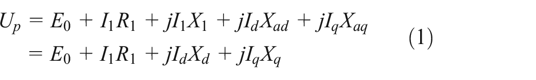
Where E0, Up, I1, R1, Xad, Xaq, and Xl denote no-load back potential of each phase, stator phase voltage, stator phase current, stator winding resistance of each phase, direct-axis reaction reactance, quadrature-axis reaction reactance, and stator leakage reactance, respectively. Besides, Xd and Xq denoting reactance of direct-axis and quadrature-axis, respectively, are expressed as:

And Id, Iq denoting armature current of direct-axis and quadrature-axis, respectively, are expressed as:

Where, ψ denotes the internal power factor angle between Il and E0, furthermore, ψ is positive when Il is ahead of E0.
In terms of equation (1), several typical steady running vector diagrams of PMSM in different conditions can be drawn as follows.
In Figure 1, Eδ, Ed, θ, and φ respectively denote air gap synthesis potential, direct-axis internal potential, power angle, power factor angle. In the Figure 1(a) to (c),

And then


Several typical steady-state running vector diagrams of PMSM: (a) φ > θ; (b) φ = θ (c) φ < θ (d) φ = 0 (e) φ < 0.
Analysis and calculation of steady-state running characteristics
Steady-state running characteristics of PMSM include the relationships between efficiency η, power factor cosφ, power input Pin, armature current Id/Iq and power output Pm, etc., which can be derived from the vector diagrams and the internal electromagnetic relation.
It can be seen from Figure 1 that internal power factor angle ϕ and power factor angle φ are expressed as follows:

And then direct-axis armature current Id and quadrature-axis armature current Iq can be derived from equations (6) and (7), furthermore, stator phase current Il can be calculated as bellow:

Power input Pin can be derived as follows:

Ignoring stator resistance Rl, electromagnetic power Pem of PMSM can be derived from eq. (9) as bellow:

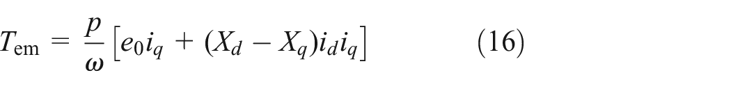
Electromagnetic torque Tem can be obtained through dividing Pem by mechanical velocity Ω as follows:

Where ω denotes motor electric angular velocity and p denotes pole pairs of motor.
Vector control principle of PMSM
Mathematical model of dq axis is the most typical method to be used to study the PMSM controlled by sine-wave current, which can not only analyze steady-state performance but also the transient performance of PMSM.
Mathematical model of dq axis
To establish mathematical model of dq axis for sin-wave PMSM, assume that firstly:
I. Ignoring the saturation of the motor core;
II. Regardless of eddy current and hysteresis loss in the motor;
III. Motor current is a symmetrical three-phase sine wave current;
The relation between the variables (i.e., id, iq) in the dq axis system of motor and the actual variables (i.e., iU, iV, and iW) in the three-phase system can be obtained by coordinate transformation (e−jθ ) as bellow:

Where, θ denotes position signal of motor rotor, that is, the angle between axis of magnetic pole of rotor and axis of U-phase stator. And i0 denotes zero-axis current (for three-phase symmetric system, i0 = 0).
For most sine-wave speed regulating PMSMs, there is no damper winding in rotor, therefore, the voltage, flux, and electromagnetic torque equations of PMSM can be simplified as follows:

Where, if denotes equivalent excitation current, and if = ϕf/Lmd, ϕf denotes flux, and ϕf = e0/ω, e0 =
Because the vector

By substituting equation (14) into Tem of equation (13), then

For PMSMs, Lq is generally required to be greater than Ld, therefore, the direct-axis current component id of the motor should be negative, that is, β > 90°.
When the motor is running stably, electromagnetic torque Tem can be expressed as:
Stator voltages of motor ud and uq can be expressed as:

Input power Pin can be expressed as:

Electromagnetic power Pem can be expressed as:

Vector control is actually to control the phase position and amplitude of motor stator current vector. It can be concluded from equation (15) that motor torque Tem depends on the space vector
Since the current actually fed into the motor windings are three-phase AC current iU, iV, and iW, therefore, the instruction value of the three-phase current

In the above equation, the position signal of motor rotor is provided by the position sensor (e.g., the photoelectric encoder). Through the control loop of current, the actual input three-phase current iU, iV, and iW of the motor can be consistent with the given instruction value
Voltage limit ellipse and current limit ellipse
The running control of PMSM is closely related to the inverter that restricts the operation performance of motor. Most significantly of all, the limit phase voltage ulim and the limit phase current ilim of PMSM is restricted by the DC side voltage and the maximum output current of inverter.
When motor is running stably, the amplitude of stator voltage vector is given as:

By substituting equation (17) into the above equation and ignoring resistance voltage drop, then the voltage u of motor running stably can be derived as follows:

By replacing ulim with u in above equation, then

Obviously, equation (23) is an elliptic equation when
Voltage limit ellipses and current limit ellipse.
The current limit equation of PMSM is given as:

In above equation,
Constant torque trajectory
When

Where, current base value ib = ϕf/(Lq − Ld) and torque base value Tb = pϕfib.
Figure 3 shows a group of torque curves with different torque per unit values on plane

Constant torque trajectory.
Whether in the second or the third quadrant, the stator current vector corresponding to any point on the constant torque trajectory of an instruction value will lead to the same value of motor torque, which involves seeking smallest amplitude of stator current vector. Because of the smaller the stator current is, the higher the motor efficiency and the lower the inverter capacity required. In Figure 3, the point of an instruction value that closest to the origin of coordinates on the constant torque trajectory is the vector of the minimum current required to generate the torque. Connecting the minimum current points required to produce different torques will form the maximum torque/current trajectory of motor, as shown in Figure 3 with solid lines.
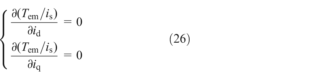
Maximum torque/current control
Maximum torque/current control is the widely used current control strategy for PMSMs. When the control strategy is adopted, current vector of the motor should satisfy
By substituting equation (16) and

Where p denotes saliency ratio of motor, and
Expressing above equation as per unit value and being substituted into equation (25), the relationship between the components of quadrature axis and direct axis current and electromagnetic torque can be deduced as:

In this case, the stator current components

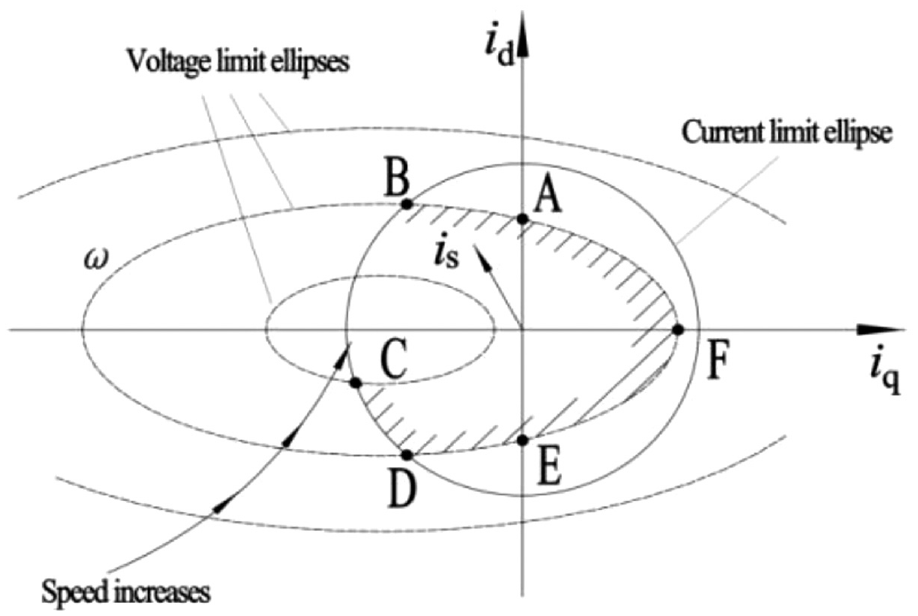
For any given torque, the maximum torque/current control of motor can be realized by calculating the two components of the minimum current as the control instruction value of current according to the above equation. As shown in Figure 4, the maximum torque/current trajectory of the motor intersects with the current limit ellipse at point A1, and the speed corresponding to the voltage limit ellipse passing through point A1 is ω1. On the OA1 section of the maximum torque/current trajectory, the motor can operate with constant torque at each point on the trajectory, and the motor speed corresponding to voltage limit ellipse passing through the point is the turning speed under the torque, while the intersection point A1 corresponds to the motor rotation speed at the maximum output torque. It can also be seen from Figure 4 that the greater the torque values during constant torque operation, the lower the turning speed of the motor. Since the voltage and current of the motor cannot exceed their respective limits during operation, the corresponding torque at point A1 is the maximum torque that the motor can output. At this time, the voltage and current of motor both reach the limit value.

Stator current vector trajectory.
By solving equations (24) and (27) simultaneously, the quadrature axis current iq and direct axis current id of the motor can be obtained as follows when the motor adopts the maximum torque/current control and the current reaches the limit value (i.e., when the maximum torque/current trajectory intersects the current limiting circle).

When the terminal voltage and current of the motor reach the limit value, the turning speed Ωb of the motor can be deduced from the above equation and the voltage equation.

Where,
Vector control system of PMSM
Traditional vector control is susceptible to external disturbances and parameter mismatches, leading to deterioration in control performance. 15 Currently, Model Predictive Control (MPC) has received widespread attention due to its fast dynamic performance, simple concepts, and multivariable control advantages. 16 Combination of fault-tolerant control with MPC and sensorless control with MPC was achieved, which has a faster dynamic response, simpler control loop, and stronger robustness compared to the combination with traditional FOC.17,18 Other motor control technologies, such as Finite-control-set model predictive control of PMSM drive systems, 19 Fault-tolerant operation of a six-phase permanent magnet synchronous hub motor based on model predictive current control with virtual voltage vectors, 20 and Speed sensorless model predictive current control based on finite position set for PMSHM drives 21 are introduced in the relevant literature respectively.
Three-winding AC transformer (capacity: 1600 kVA, voltage level: 10 kV, 660 V, and 380 V) is used as the total power supply, where 660 V is used as the power supply of PMSM’s driver.
The control system of PMSMs installed in the “VFD room” adopts the cabinet combined the rectifier and inverter (‘VACON’ vector frequency conversion system), as shown in Figure 5, which consists mainly of filter, rectifier, inverter and brake unit, etc.

Combined cabinet of control system for PMSMs.
Electrical schematic diagram of the driver for PMSMs is shown in Figure 6. The 660 V power output from transformer passes through the MCCB (circuit breaker) into the frequency conversion system. Input reactor is used to restrict the current peak, and input filter is used to reduce the content of harmonic current. Rectifier bridge circuit with high power thyristors is used to change AC current into pulsating DC current. DC bus is used to supply DC current for the inverters (IGBT). Output filters is used to reduce the output harmonic content of IGBT. Output reactor is used to restrict the current peak of the motor. Brake unit is actually a programmed switch to turn off or turn on the DC circuit of brake resistor, which can realize the function of energy consumption braking. Besides, PID closed-loop parameters control method base on servo drive mode was used to improve speed control accuracy.

Electrical schematic diagram of driver for double PMSMs.
It can be seen from the Figure 6 that, firstly, common DC bus as the new innovation point used to supply DC currents for the two motors simultaneously, which make the structure of this frequency conversion system more concise and compact. Secondly, the use of the brake resistors makes the potential energy converted into heat energy consumed when the hook falls, which better protects the control system.
Application and test
Application
Drawworks is the core component of drilling rig’s lifting system, unlike traditional mechanical drilling rigs, this electric permanent magnet variable frequency drilling rig (Model: DBZJ40-Z) adopts a direct-drive system with double PMSMs as its main drawworks mechanism. Comparing with the mechanical drilling rigs with the variable frequency asynchronous induction motor and gear box as the drawworks mechanism, this drilling rig (DBZJ40-Z) apparently has a more compact and concise structure of drawworks, 3D model of DBZJ40-Z is shown in Figure 7 and the real object is shown in Figure 8(a). Besides, the “VFD room” as the motor control center including the vector frequency conversion system as shown in Figure 5 is placed next to the motor.

3D model of DBZJ40-Z drilling rig: (a) Isometric view, (b) Front view, (c) Side view, and (d) Rear view.

(a) DBZJ40-Z drilling rig, and (b) drawworks with double PMSMs.
The drawworks real object and 3D model with double PMSMs are shown in Figures 8(b) and 9, respectively. It can be seen from Figure 9 that double PMSMs, winch, four brake calipers and two brake discs are the main components of the drawworks. In addition, it is worth noting that the rope groove named “Lebus” be able to realize the function of automatic arranging for long steel wire rope, which replaces the traditional cam arranging steel rope device.
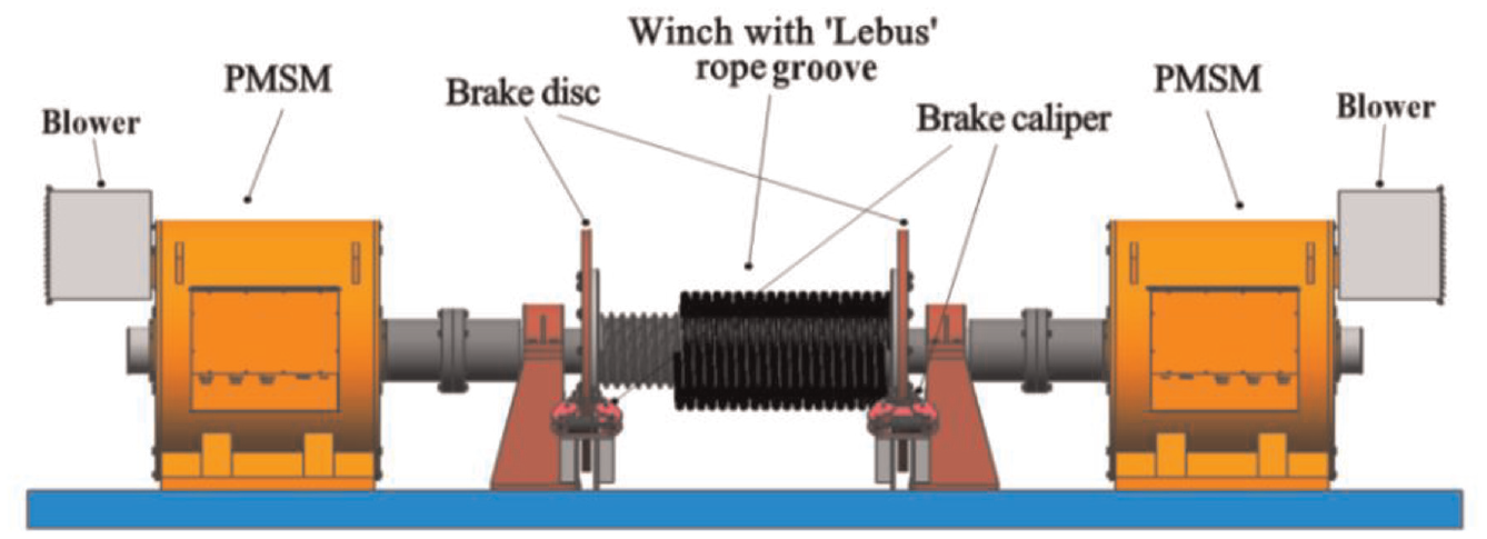
3D model of drawworks assembly with double PMSMs.
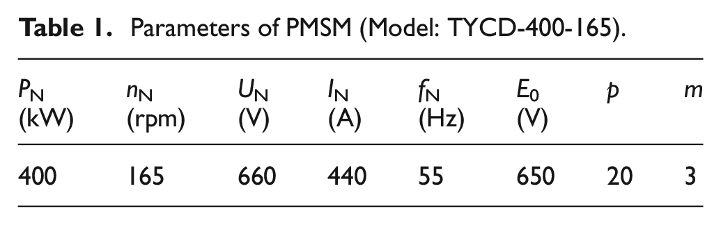
In order to satisfy the standard requirements of 4000 m drilling rig for motor power of drawworks (i.e., equal or more than 750 kW), 22 double PMSMs of the same model (400 kW each) are used as the drawworks driving device. The parameters of PMSM are listed in Table 1.
Parameters of PMSM (Model: TYCD-400-165).
Test
The running characteristic test of drawworks’s PMSMs depends on drilling project. This drilling project uses DBZJ40-Z drilling rig to carry out the construction. This design well depth is 2000 m, of which 0–750 m is the vertical well section and 750–1300 m is the directional deviated well section, 1300–2000 m is the horizontal well section.
Since the directional deviated well section (750–1300 m) is of the most complex drilling characteristics, therefore, three different well depths (1064, 1180, and 1267 m) close to the bottom of this section 1300 m were selected as the test starting points to investigate the running characteristics of drawworks’s PMSM. Drilling parameters of these three different starting points of well depths are list in Table 2 as follows:
Drilling parameters at the three different starting points of well depths.

Typical drilling process of each drill pipe consists of three stages: (I) lowering drill string; (II) constant pressure/speed drilling; (III) lifting drill string. According to the description above, in this test, the running characteristics of PMSM were investigated by drilling a drill pipe (Length: 9.7 m, Diameter: 89 mm) from each starting point at three different depths. In order to analyze the running characteristics of the PMSM under different control speeds, meanwhile, considering the technical requirements of practical drilling, different drawworks speeds (i.e., motor speeds n) were given by the control handle at the three stages of each test point as shown in the Table 3.
Motor speeds n given at the three stages of each test point (rpm).

When PMSM is running steady-state, the relevant parameters of the vector variable frequency system can be monitored through the control panel interface in the driller room as shown in Figure 10. Figure 10 shows the driller’s operating platform, where various drilling parameters (e.g., hook load, drilling speed and hook height, etc.) and electrical parameters (e.g., control voltage, common bus current and voltage, etc.) can be measured through the left “Touch control panel.” The right “Monitor panel” is only used to monitor the key vision sites. It can be seen in the Figure 10(b) that the main interface on the “Touch control panel” is mainly used to show the drilling parameters. In addition, the drawworks’s PMSM monitoring interface Figure 10(c) can be opened through the bottom switch toolbar on main interface, as shown in the Figure 10(b). Relevant electrical parameters about the vector variable frequency system and PMSM can be monitored on this interface, as shown in Figure 10(c).

Monitor interfaces: (a) Driller’s console, (b) Main interface, and (c) Motor monitoring interface.
In order to investigate and analyze the running characteristics of the drawworks’s PMSMs in these three measure stages of each test depth, control voltage Uc, common DC bus branch current IB, DC bus voltage Ud, and motor torque T with time t as the horizontal axis shown in Figure 6 were measured, as shown in Figure 12(a) to (d).
It’s noting that parameters IB and Ud are the monitoring parameters of the DC bus, as shown in Figure 6, the product result of them represents the power consumption of the frequency converter when motor is running, which includes the power consumption of motor and frequency converter. Therefore, it is necessary to measure the power PM and power factor cosφ of PMSM in real time through the measuring meter (MS2205) for further analyze the characteristics of motor itself. This meter MS2205 can measure the driller’s console-time power, power factor, voltage and current, etc. of equipment or power supply, but also has the function of data recording. Technology parameters and real object of the meter MS2205 are listed in Table 4 and Figure 11(a), respectively. The measuring principle and method are shown in Figure 11(c).
Main technology parameters of meter MS2205.


Measurement principle of MS2205: (a) MS2205 meter, (b) Measure method, and (c) Measure principle.
As shown in Figure 11(b), three different color measuring wires with clamps of the meter MS2205 were connected respectively to the three input terminals of the motor. In view of that the PMSM is three-phase balanced load, meter’s head can be stuck on anyone of the motor power wires (i.e., L1, L2, or L3) for measuring, and the measuring results of parameters would be the same (e.g., power, power factor, current and voltage, etc.).
Based on the measuring method of meter MS2205, the data measured of the PMSM at the three stages I, II, and III) of each test process (1064, 1180, and 1267 m) could be compared with the DC bus parameters of the frequency converter monitored on the “Touch control panel” as shown in Figure 10(c).
Motor torque T, power PM and power factor cosφ of PMSM with time t as the horizontal axis were measured in these three measured points respectively as shown in Figure 12(d) to (f). In addition, the numerical simulation results of T, PM and cosφ are also shown respectively to verify the theoretical analysis.

Parameters measured curves of frequency converter and PMSM: (a) UC measurement at the three stages, (b) IB measurement at the three stages, (c) Ud measurement at the three stages, (d) Verification of numerical simulation TI, (e) Verification of numerical simulation PM, and (f) Verification of numerical simulation cos φ.
Discussions
Measuring variables of the curves shown in the Figure 12(a)–(d) are obtained from drawworks’s PMSM monitoring interface as shown in Figure 10(c).
It can be seen from Figure 12(a) that the control voltage Uc varies during the three different stages I, II, and III) of each test process. Specially, Uc is much higher during the stages of string lowering and lifting than the stage of constant speed/pressure drilling. Furthermore, according to Table 3, it can be seen that the value of the control voltage Uc is not the same during the string lowering I) and lifting (II) stages at different test depths (1064, 1180, and 1267 m), but the value of Uc is basically the same during constant speed/pressure drilling stage. The reasons for the above results can be attributed to the fact that the voltage-frequency ratio (U/f) of the frequency converter is a constant, that is, the value of the ratio between different speeds n and different control voltages Uc is equal. If the motor speed n is expressed as per unit value n*, according to the parameters of PMSM in Table 1, the ratio of Uc/f can be converted to the one of Uc/n*, as shown in Figure 13(a).

Running characteristics curves of PMSM.
Figure 12(b) shows that the common DC Bus branch current IB of each motor varies during the three different stages I, II, and III) of each test process. Specially, IB is much higher during the stages of string lowering and lifting than the stage of constant speed/pressure drilling. The reasons of above results can be attributed to the fact that there is no pump pressure in the stages of drilling string lowering and lifting, and the load of the motor is completely the weight of the drill string, therefore, the current IB is relatively large (i.e., the motor torque TM is relatively large). However, in the stage of constant speed/pressure, the drill string has completely arrived the bottom of the well, and according to the drilling process requirements, the pump pressure at this stage is around 10 MPa (as the Pd listed in Table 2), and the weight of the drill string is basically balanced, therefore the current IB is very low. The correlation curve of the current IB (i.e., Il) and the motor torque TM is shown in Figure 13(b).
Figure 12(c) shows that the voltage Ud of common DC Bus is no significant change in the three different stages I, II, and III) of each test process. However, according to the given values of motor speed n in three stages of each test process in Table 3, it can be seen that DC bus voltage Ud is in direct proportion to speed n, that is, the higher the n, the higher the Ud, conversely, the lower the n, the lower the Ud.
Figure 12(d) shows that the curve of motor torque T has similar characteristics to the curve of current IB, as shown in Figure 12(b). The reasons of above results can be attributed to the approximately direct proportional relationship between T and IB (i.e., Il), shown in Figure 13(b). Measuring variables of curves shown in the Figure 12(e) and (f) are obtained from the meter MS2205.
Figure 12(e) shows that the power PM has a significant change in the three different stages I, II, and III) of each test process. The motor power PM is significantly higher than that in the constant speed/pressure stage during the drilling string lowering and lifting stages. The reasons can be attributed to the fact that the load of motor is the weight of the whole drill string in the lowering and lifting stages, however, in the constant speed/pressure stage, the weight of the string is basically balanced by stratum because the string has completely arrived the bottom of well, and add the reaction of the pump pressure Pd, the load of motor is significantly reduced. The power-current curve of motor measured by meter MS2205 and the DC bus power-current curve measured by drawworks’s monitoring interface are shown in the Figure 13(c). Through comparison, it is found that with the increase of stator phase current Il (i.e., the increase of load), the power consumption PC of frequency converter becomes larger and larger. The reason of above results can be attributed to the fact that with the increase of Il, power consumption of IGBT also increase.
Figure 12(f) shows that the power factor cosφ of motor is no a significant change in the three different stages I, II, and III) of each test process. The values of cosφ during the stages of string lowering and lifting are slightly greater than those during the stage of constant speed/pressure. The reason for the above results can be attributed to the increase of the power factor cosφ of motor with the increase of the load of motor.
Figure 13(d) shows that the cubic polynomial fitting curves (based on the least square method) of power factor cosφ and efficiency η of motor with power per unit value P* (PM/PN) as the horizontal axis. Where, sampling point values of cosφ and PM could be directly measured by the meter MS2205, however, η needs to be derived from the following equation:
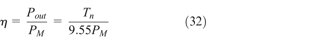
Where, n and T can be measured from drawworks’s monitoring interface, as shown in Figure 10(c). It can be seen from Figure 13(d), the power factor cosφ and efficiency η of the motor increase with the increase of the power of motor, but the overall value of cosφ and η are satisfactory.
Conclusions
The following conclusions can be drawn from the application and test results:
Multipoles PMSM with vector frequency conversion and speed regulation as the drive device of drawworks can greatly improve the speed control accuracy of the drawworks (e.g., the speed can be reach 0.03 rpm at 0.01 Hz) and eliminate the complex deceleration mechanism. Compared with traditional structure of variable frequency induction asynchronous motor with gearbox (because of the unstable characteristics of induction asynchronous motor at low speed, it is necessary to rely on the gear box to decelerate the end speed of equipment), the structure of the drawworks with PMSM is more compact and concise.
It can be seen from the drilling process that most of the time in the drilling process is constant speed/pressure drilling stage, which is relatively long, and the motor power consumption at this time is very few. In contrast, the time in the lowering and lifting stages is very short, but the power consumption is high. Besides, test results that the power factor cosφ and efficiency η of the PMSM are satisfactory during the whole drilling process (power factor cosφ above 0.9, efficiency η above 0.8). Compared to induction asynchronous motors (power factor cosφ is 0.65–0.8, efficiency η is 0.5–0.7), overall, the utilization of PMSMs has significantly reduced the power consumption of the drawworks in drilling process.
The speed of PMSM can be regulated by constant torque within the rated speed range (i.e., the torque value can remain constant). Besides, the torque increases linearly with the increment of the poles. In addition, it is worth noting that the PMSM can use electromagnetic torque to achieve on-load hover function, which makes the structure of the brake safety system much simpler than ever.
The accuracy of the theoretical analysis of torque, power, and power factor of PMSM are verified by the running characteristics tests of the drawworks at the different working conditions.
Footnotes
Appendix
Acknowledgements
The author(s) would like to thank the electrical engineer (Zhankong Hu, Huaihe Energy (Group) Co., Ltd) for his contribution in the research work of this paper.
Handling Editor: Chenhui Liang
Declaration of conflicting interests
The author(s) declared no potential conflicts of interest with respect to the research, authorship, and/or publication of this article.
Funding
The author(s) disclosed receipt of the following financial support for the research, authorship, and/or publication of this article: This work was supported by the International Technology Cooperation and Exchange Project (3500 m permanent magnet direct-top driver geological drilling rig), Grant No. 2015DFA70300.