
Abstract
Spiral bevel gears are manufactured and used in pairs. When one part usually pinion fatigued, the pair will be replaced. It inevitably leads to a waste of resources and time. To solve this phenomenon, a method to remanufacture pinion with ease-off topology modification is proposed. First, the wheel and pinion were measured to fitting tooth surface, and then a conjugate surface of wheel fitting tooth surface was derived. Secondly, an ease-off topology surface was superimposed to the conjugate surface to improve mesh performance, and then a design tooth surface was obtained. Thirdly, a mathematical model to process pinion was established and original machine-tool settings parameters of pinion were calculated. The deviations between design and original tooth surface of pinion were count, and an error correction model of tooth surface was established to adjust machine-tool settings parameters. Finally, an experimental verification was conducted. The pinion was remanufactured by a face-milled generator and the mesh performance was consistent with design. The result demonstrates the method proposed is effectiveness and feasible. It provides reference for the remanufacture of large-size spiral bevel gears and has good value for engineering application.
Introduction
Spiral bevel gears are widely used in industrials for its advantages of driving smoothly, high transmission efficiency, excellent load capacity, and so on. Many researches have been done in design, modification, and manufacture for spiral bevel gears. Litvin et al.1–3 proposed a method to improve mesh performance and reduce vibration and noise by local synthesis, tooth contact analysis, and finite element analysis. Perez et al. 4 calculated the basic machine-tool settings from blank data for face-milled hypoid gears. Zhang and Yan 5 and Zhang et al. 6 proposed a new methodology to manufacture spiral bevel and hypoid gears by duplex helical method in which introduced duplex helical method in detail. Geng et al.7,8 and Yang et al.9,10 also researched the process of spiral bevel gears by completing method. For tooth surface modification, Wang and Fong 11 put forward a modified radial motion to modify pinion tooth surface, Su et al. 12 developed a seventh-order polynomial function of transmission error to reduce running vibration and noise. Kolivand and Kahraman 13 raised a methodology to determine unload contact patterns based on ease-off topography. Suh et al. 14 presented a crow model along spiral curve direction and involute direction, separately, Ship 15 introduced an ease-off flank modification methodology for spiral bevel and hypoid gears. Chen et al. 16 presented a direct preset method for solving ease-off tooth surface of spiral bevel gear that preset contact path (CP), geometric transmission error (TE), and curvature of difference curve at contact point. Mu et al. 17 proposed an innovative ease-off flank modification method based on dynamic performance for high-speed spiral bevel gear with high-contact-ratio to reduce running vibration.
For tooth surface measurement, Zhang et al. 18 according to three coordinates test machine obtained digital gear faces were fitted by NURBS (non-uniform rational B-spline). Li et al. 19 proposed a new digitized reverse correction method based on measurement data from a one-dimensional probe to improve tooth surface geometric accuracy and transmission quality of hypoid gears. Du and Fang 20 proposed an active tooth surface design methodology for face-hobbed hypoid gears based on measuring coordinates, which provides a new approach for meshing performances control of face-hobbed hypoid gears in phase of trial-manufacture.
The above researches are the latest development of spiral bevel gear while are all active design that the pairs are process as design. Nevertheless, there is a limited that it must be processed in pairs and can’t be interchanged due to its complex space surface. As a result, one of the pair is damaged usually the pinion, it can’t operation normally. Especially the pair using in mining machinery which is large-size without protective, broken and wear of tooth are frequent occurrence due to the complex working conditions. As a general, the pair has to be replaced even though the wheel is undamaged. This phenomenon leads to high economic cost and contrary to concept of green manufacturing. Therefore, it is necessary to propose a method to remanufacture pinion to match wheel. It not only has a certain demand but also economic benefit.
For gear remanufacture, Kawasaki et al. 21 presented a method for remanufacturing pinion member of large-sized skew bevel gears using a CNC machine center and respecting an existing gear member. Lei et al. 22 introduced a method to remanufacture a pinion on a 5-axis CNC machining center by ball-end. The above two literatures put forward the gear remanufacture by CNC machining center which is time-consuming and mesh performance are not considered. Ames 23 focused on repairing spiral bevel gears of high value or high demand. The micromachining process (MPP) was introduced to repair technique for spiral bevel gears to enhance mesh performance and durability. Chen et al. 24 researched spiral bevel gear remanufacturing technology based on profile modification, while only contact failure is analyzed not suitable to bending fatigue. Currently laser cladding as a remanufacturing technology is apply to tooth surface repair 25 while the distance is more than 0.7 mm between the profile of coating and original tooth surface which will impact contact performance.
Inspired by the above literatures, a method to remanufacture large-sized pinion with ease-off topology modification by face-milling generator to match existing wheel is proposed. The remanufactured pinion will be manufactured by face-milling generator. It is time-saving compared to machining centers. At the same time, the meshing performance is guaranteed by ease-off topology modification. It is a key technology to obtain machine-tool setting parameters that meet meshing performance. The detail flow chart to remanufacture pinion is shown in Figure.1.
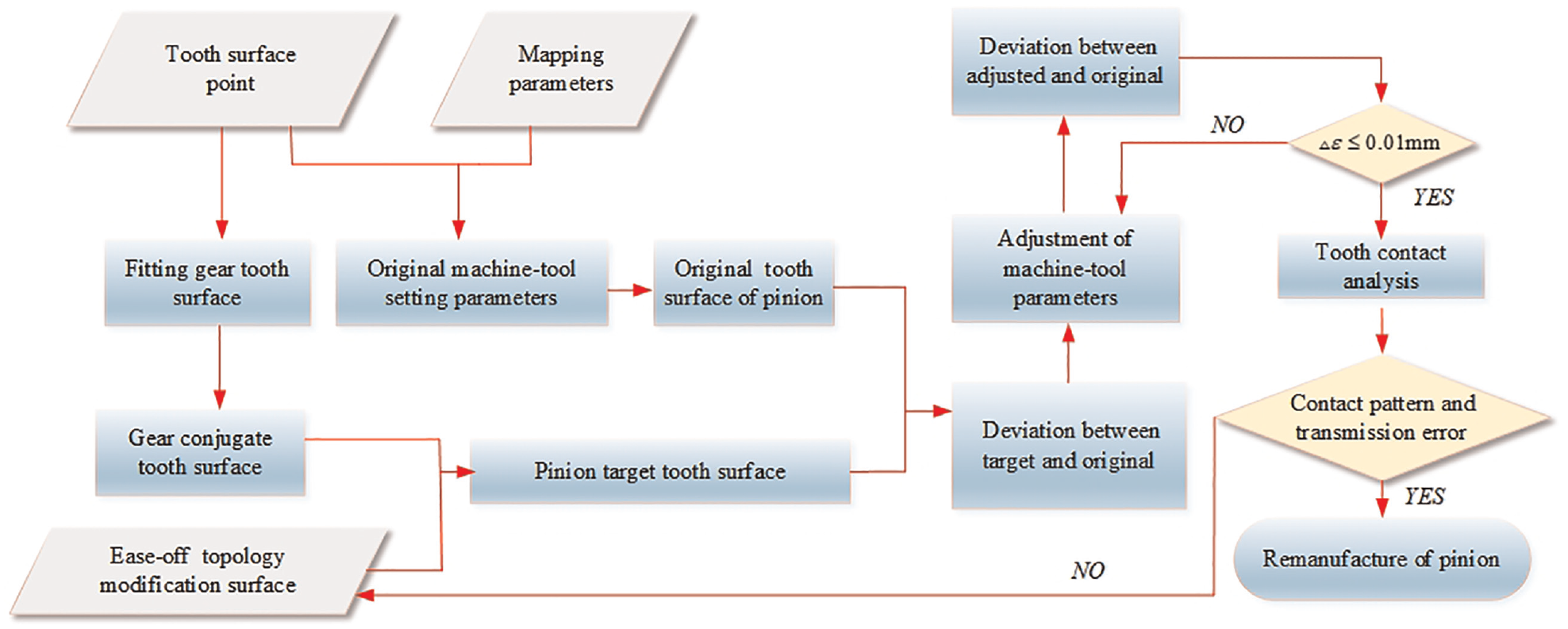
Flow chart to remanufacture pinion considering ease-off topology modification.
Derivation of original tooth surface
Tooth surface data are usually obtained by measuring instrument or measuring center. A assume that complete measurement data of failure pinion tooth surface can be obtained.
Fitting of wheel tooth surface
Considering tooth surface data of wheel (Figure 2(a)) as the inputs then the control vertices (Figure 2(b)) can be obtained toward the direction of

Here,
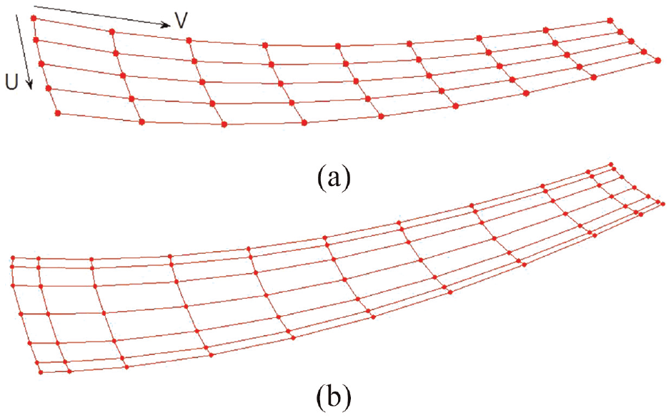
Tooth surface fitting: (a) diagram of points and (b) control vertex.
The position vectors

Deduce of pinion tooth surface
Mathematical model of pinion process is established as illustrated in Figure 3. Coordinate system

Mathematical model of process pinion.
The position vector can be represented in tool coordinate system

Here
The pinion position vector in coordinate system

Here,
Then mesh equation during process can be represented as

Usually, tooth surface geometry can be numerically represented by a group of surface point in project plane. A grid of


Definition grids of tooth flank.
Surface parameters
While machine-tool setting parameters of failure pinion are unknown in most cases. As a result, a basic machine-tool setting parameters are given, after repeated measurement and modification until measurement deviation is acceptable. 26 In this paper, the biggest deviation is less than 0.05 mm and the corresponding machine-tool setting parameters are defined as original. Then original tooth surface of pinion can be derived by equation (4).
Establishment of design tooth surface
As mentioned in section “Deduce of pinion tooth surface,” tooth surface deviations between failure pinion and measurement are unavoidable. So, the failed tooth surface cannot be completely replicated. In this paper, a conjugate tooth surface of wheel is constructed and modified to reduce the impact of tooth surface deviation on meshing performance. Firstly, the conjugate tooth surface of wheel is solved, and then ease-off topology modification surface is established. Based on conjugate tooth surface and ease-off topology modification surface, a design tooth surface is set up. The detailed is as follows.
Solving conjugate tooth surface of fitting wheel
Mesh coordinate system of spiral bevel gears is established as shows in Figure 5.

Mesh coordinates system.
Meshing equation can be expressed as

Here

The relation accord with full conjugate is essential as

Then position vector

Here,
Construction of design tooth surface
Tooth surface modification is a common method to improve mesh performance. In most cases, such as pressure angle, spiral angle, curvature of tooth length, tooth profile, and torsion are modified. In this paper an ease-off modification surface along tooth length and tooth profile is put forward and expressed as

Here,
As showed in Figure 6,
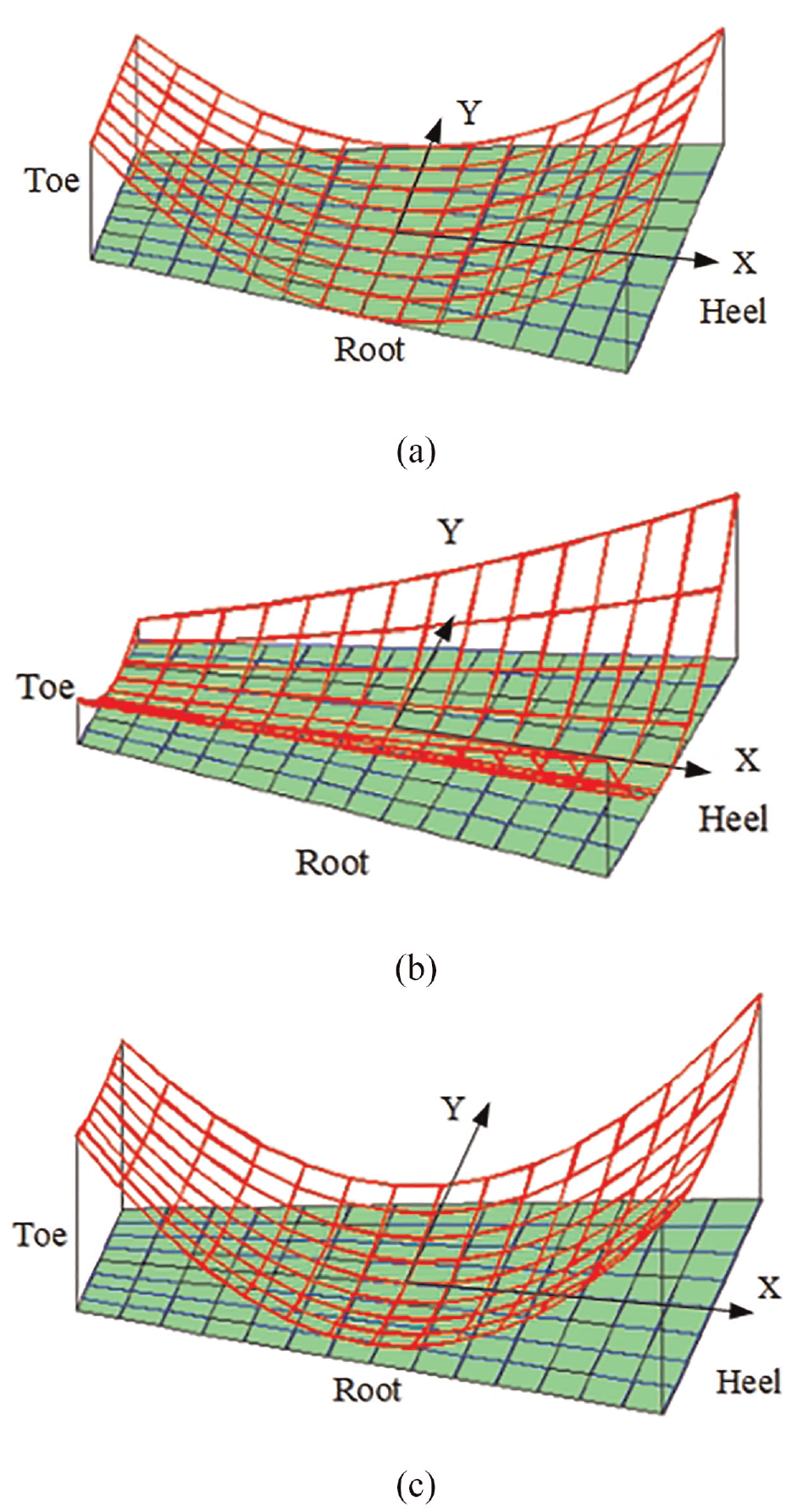
Modification of tooth surface: (a) tooth length curvature modification, (b) tooth profile curvature modification, and (c) synthesis modification.
Then a design tooth surface can be established according to equations (9) and (10).

Adjust machine-tool setting parameters of pinion
Mesh performance is guaranteed by tooth surface modification, then it is a key to calculate machine-tool setting machining parameters corresponding to design tooth surface. In order to reduce deviations between design and original tooth surface, the original machine-tool setting parameters are adjusted. The correction method has been broadly developed and proven to be reliable and effective in literature. 15
First the deviations between design and original tooth surface can be expressed as

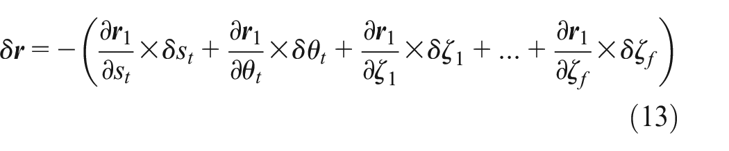
Then differential of equation (12) can be expressed as
Taking inner product of equation (13) with surface normal
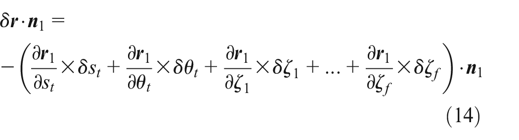
For vectors

Here,
Using

As mentioned in section “Deduce of pinion tooth surface,” the tooth surface deviation of grid points which is made up of

Here,

There are far more grid points than the machine-tool setting parameters in equation (19), so it is over determined. The least squares method is used to calculate the adjustments.
Number example
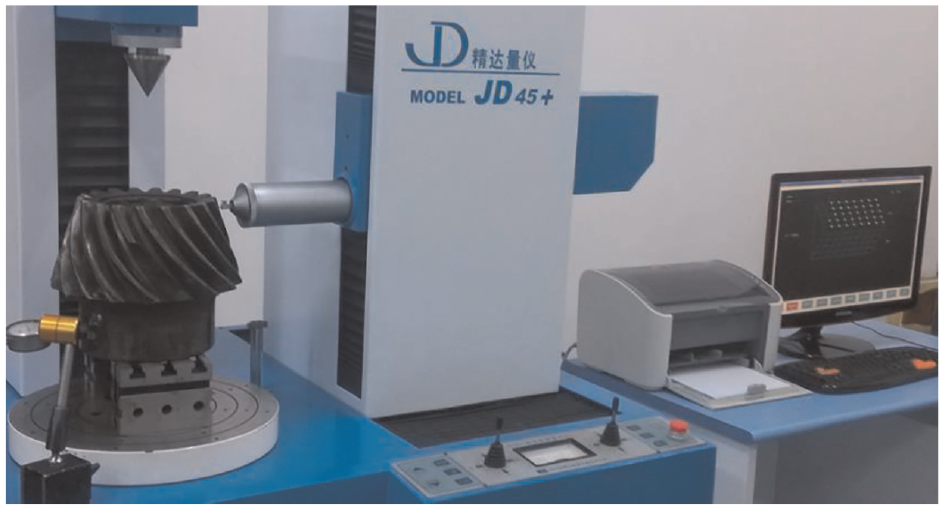
A practical case that failures pinion is remanufactured by the proposed method. The basic geometry parameters are calculated after mapped and listed in Table.1. The failure pinion is measured by measurement system JD45+ as showed in Figure 7 which can adjust machine-tool setting parameters according result of measurement. After repeated measurement and adjusting, original machine-tool settings parameters are listed in Table 2.
Basic geometry parameters.

Measurement of failure pinion.
Original machine-tool setting parameters of pinion.

Curvatures of pinion tooth length and tooth profile are modified as mentioned in section “Construction of design tooth surface.” The modification coefficients are listed in Table.3. The topology of design tooth surface is established and showed in Figure.8.
Modification coefficients.


Topology of design tooth surface: (a) concave side and (b) convex side.
As shown in Figure 8(a) is the design topology of pinion concave side. The edge grid points are modified by 0.4052, 0.411, 0.4292, and 0.4414 mm, respectively. And the flank modifications become bigger as close to the edge of tooth surface and smaller in the middle of tooth surface. Therefore, contact pattern will be located in the middle of tooth surface. Similarly, (b) is the design topology of pinion convex side. The edge grid points are modified by 0.3042, 0.3088, 0.3331, and 0.3234 mm, respectively. Then contact pattern will also be located in the middle of tooth surface.
The deviations between original and design tooth surface of pinion are calculated and displayed in Figure 9. An instruction is that the green represents the original tooth surface and the red represents design tooth surface.

Deviations between original and design tooth surface: (a) concave side and (b) convex side.
As shown in Figure 9(a) is concave side deviations between original and design tooth surface, (b) is convex side deviations between original and design tooth surface. The modifications along tooth length and tooth profile of design tooth surface are bigger than that of original tooth surface. The tooth length and profile of tooth surface are optimized, and the edge contact can be avoided.
For the limited experimental condition, the profile angle is not adjusted, and the other parameters are calculated based on equation (19). The deviations between adjusted and design tooth surface are illustrated in Figure 10.
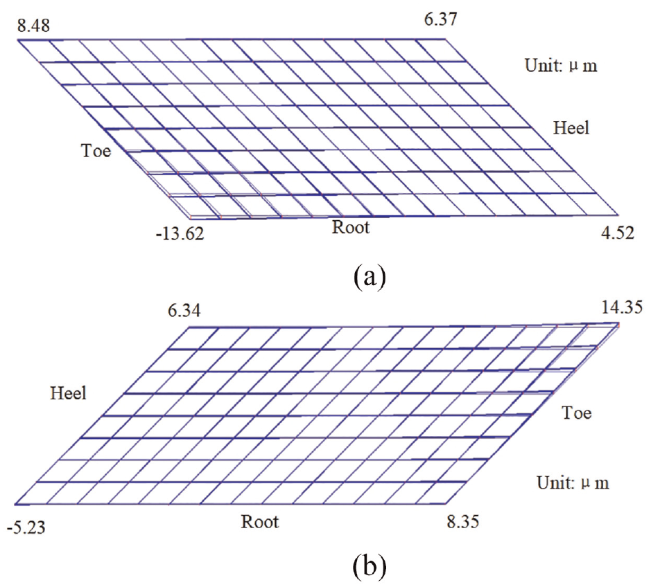
Deviations between adjusted and design tooth surface: (a) concave side and (b) convex side.
As Figure 10 showed the deviations between adjusted and design tooth surface of pinion concave side and convex side respectively. For concave side, the deviations of edge grid points are 0.00848, 0.00637, 0.00452, and −0.01362 mm. The biggest deviation is 0.01362 mm. For convex side, the deviations of edge grid points are 0.01435, 0.00835, −0.00523, and 0.00634 mm. The biggest deviation is 0.01435 mm. The engineering application shows that the impact on the contact performance of the tooth surface can be ignored when the deviation is less than 0.02 mm.
The adjustment machining-tool setting parameters of pinion are listed in Table 4. Then the tooth surface can be obtained by equation (4). Figure 11(a) is the digital tooth surface and Figure 11(b) is 3D model constructed by UG.
Adjustment machine-tool setting parameters of pinion.


Pinion model: (a) digital tooth surface and (b) 3D model.
Tooth contact analysis (TCA) is carried out based on adjusted machining-tool setting parameters and the results are showed in Figure 12.
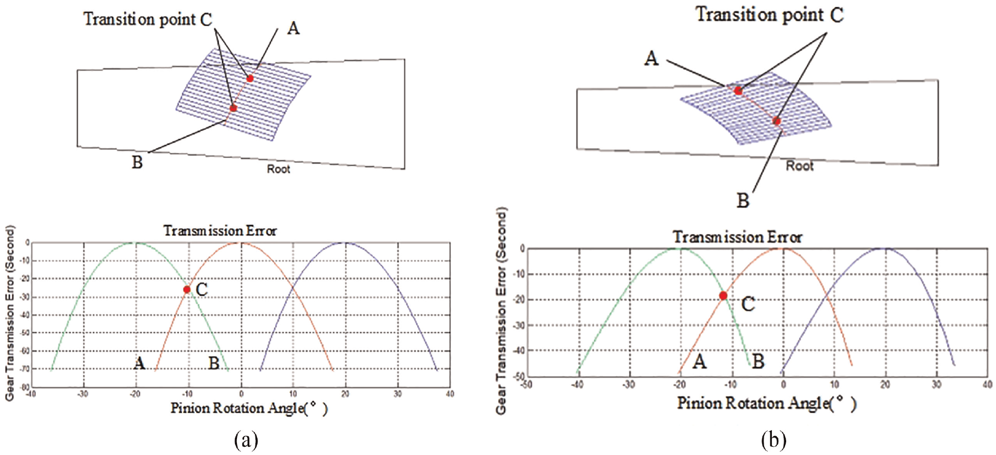
Results of TCA: (a) wheel convex side and (b) wheel concave side.
As shown in Figure 12(a) is contact pattern and transmission error of wheel convex side, (b) is contact pattern and transmission error of wheel concave side. The contact patterns are located in the middle of the tooth surface and the transmission error curves are symmetrical. The real contact pattern is located at contact points that are above the transition point
According to machine-tool setting parameters listed in Tables 2 and4, the pinion is remanufactured by YK2260T, as showed in Figure 13. After remanufactured, the pinion is measured to check quality of tooth surface as shown in Figure 14 and the result of measurement are displayed in Figure 15.
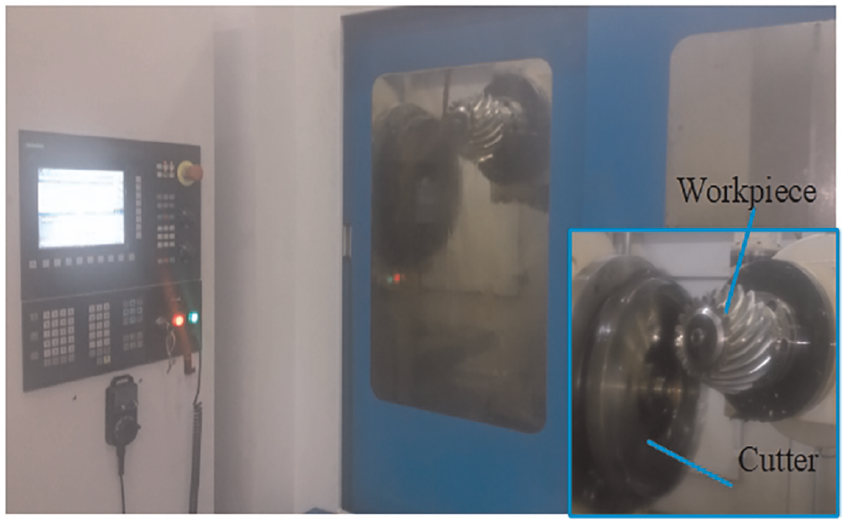
Manufacture of pinion.

Measuring of pinion.

Result of tooth surface measurement.
As shown in Figure 15, the biggest deviation of pinion convex side is 0.0321 mm located at toe which will not engaging in meshing and has no effect on the contact performance. For concave side the biggest deviation is 0.0151 mm located at heel. The causes of tooth surface deviation may be machine errors, installation errors, cutter errors, and so on, while the tooth surface deviations meet the engineering requirements.
Finally, rolling test is conducted between the remanufactured pinion and the existed wheel. There is no obvious vibration and noise during rolling test. The results are illustrated in Figure 16.

Results of rolling test: (a) rolling test, (b) convex side of gear, and (c) concave side of gear.
As showed in Figure 16(a) is scene of rolling test, (b) and (c) is contact pattern of wheel convex side and concave side respectively. Compared with the Figure 12, the results are almost identical, the tooth contact patterns are in the central and there is no edge contact occurs as designed. Although it is a little longer for wheel concave than that of design, and meet the engineering requirements. The remanufactured pinion is successfully used in the product. The results verify the feasibility and effectiveness of the proposed method.

Deviation of convex side (mm)
Deviation of concave side (mm)
Conclusions
A method to remanufacture large-sized pinion by face-milling generator to match wheel is proposed which solved the problem that pairs of spiral bevel gears must be replaced due to the failure of one component. It is time-saving compared to machining centers and meshing performance is guaranteed by ease-off topology modification.
An ease-off modification is put forward to optimize mesh performance between existed and remanufactured parts. The curvature of tooth length and profile topology is modification and the design pinion tooth surface is constructed, then the adjusting machine setting parameters correspond to design tooth surface are calculated.
The experimental results and theoretical analysis results are consistent which shows the effectiveness and feasibility of the proposed method. The method has the value of engineering applications and can also be used to other types of gear.
Footnotes
Appendix
Acknowledgements
We are grateful to the reviewers and editors for their valuable comments and suggestions.
Handling Editor: Chenhui Liang
Declaration of conflicting interests
The author(s) declared no potential conflicts of interest with respect to the research, authorship, and/or publication of this article.
Funding
The author(s) disclosed receipt of the following financial support for the research, authorship, and/or publication of this article: The authors are grateful to the National Natural Science Foundation Council of China; this project was performed under the Grant Nos. 52175049, 52005157, and 51975185, Henan Provincial Science and Technology Research Project (No. 232102220057).