
Abstract
The study summarized the characteristics of large board and shaft components. The high-end large machine equipment and clamping devices should be developed in machining for high requirements. Additionally, some non-conventional methods have became a increasing for large components. For measurements, the developing and advanced methods were summarized, and the compensation methods were also complement to realize the high precision and efficiency. If that the component’s size has greatly exceeded the range of the current equipment, the mobile equipment are recommended for machining and measurement, and its detection technology is developed essentially for multiple mobile ones. Thus the study has guiding significance for achieving the high-precision and efficiency machining and measurement for large components, which is a great need in related industries.
Introduction
Nowadays, with the increasing number of large-size components in the fields of aerospace, energy, shipbuilding, etc, the development of advanced technology for large-size components continues to accelerate, and also meet more requirements of more complex shapes and higher precision. 1 Thus, the machining, measurement, and other key technologies of large and complex components are prior in the key development areas of the machining industry. 2 Actually for different components, the large size is only a relative concept, and has different size ranges. Taking a large aircraft component for example, the size of supercritical wing can be as large as tens of meters. The length is 20–30 m, the width 3 m, and the rib size 80 mm. While for a large shaft component, the length is greater than 6 m, and the aspect ratio greater than 30.3,4
The large components can be roughly classified into two categories. One is kinds of large-board components, which the structure usually has the characteristics with large size, many thin walls, variable cross-section, and curved surface structure. 5 Those characterizes also led to obvious weaknesses, such as poor rigidity and difficult clamping, and prone to the unaccepted deformation. The other one is kinds of large-shaft components with heavy weight. 6 The dimensional accuracy, shape and position accuracy, especially for high-precision and high-efficient requirements, are difficult to guarantee. In cutting such a long shaft, the tool wear is serious in turning. 7 It is almost impossible to complete the full-length machining without changing tools. If the tool is changed during the cutting, the machining accuracy and efficiency would be greatly reduced.
In machining, the dominant directions of large-board components are of the length and width which can be considered as two-dimensional problems. The deformation mainly due to the inappropriate clamping force, 8 over-cut, 9 and unfavorable residual stress. 10 Apart from internal residual stress before processing, the machining caused residual stress was depended on strong thermal-mechanical coupling field of cutting, 11 which affects the overall deformation of the large-board component. For large-shaft components, the dominant direction is the direction of length which can be considered as a one-dimensional problem. The fixtures cannot be without adding intermediate support for cutting such a long component.12,13 And for higher surface, the fine grinding of a common-size shaft is not appropriated for a large-size shaft due to several hours to several days’ cutting, which is with low efficiency and easy to cause severe heating, even burns and cracks. 14 Additionally, some traditional measurement methods were difficulties in obtaining favorable precision and efficiency for large components.
Based on different characteristics of large components, the needs for advanced technology and equipment of machining and measurement are urgently, especially satisfying the high precision and efficiency requirements. The study summarized the machining from points of clamping devices, large machine equipment, mobile machine equipment, and other machining methods, and the measurement from that of developing and advanced methods.
Machining of large components
As the components’ size gradually increases, the installation, and positioning were excess or over positioning. The large-board component cannot be installed on a three-joint support, and the large-shaft component cannot without adding intermediate support. The fixtures 15 are crucial for balancing and offsetting the large components’ deformation induced by gravitational and support-clamp loads.
In machining the large components, it would last from several hours to several days. The temperature and cutting force can change significantly the structure. 16 Thus, the gravitational and fixture loads induced mechanical deviations, the temperature induced thermal deviations and the cutting forces induced mechanical deviations should be united as a system to obtain a high precision and efficiency.17,18
Clamping devices
For controlling the deformation of large components, the positioning and clamping are important.19,20 The multi-point supporting and clamping technology are effective to solve the machining problems of large components. The multi-point effect makes the clamping force acting on the workpiece more evenly distributed, which can avoid the clamping deformation caused by excessive concentration. 21 Meanwhile, it also increases the processing stability and system stiffness.
A number of special tooling, such as hydraulic adjustable tooling, 22 vacuum adsorption tooling, 23 flexible automatic tooling, 24 and adaptive positioning system, 25 were used. Firstly the hydraulic adjustable one (Figure 1(a)) directly uses the NC machining program to control the clamping device, realizing the automatic tool hiding, and greatly improves the processing efficiency. Then the vacuum adsorption one (Figure 1(b)) applies the wireless communication technology of multi-degree freedom robot to design the adaptive multi-point positioning. Lastly the flexible automatic one (Figure 1(c) and (d)) controls every support rod to realize the positioning, supporting, and clamping of large components in three-dimensional coordinate.26,27

Tooling system: (a) hydraulic adjustable system, (b) vacuum adsorption system, (c) TORRESTOOL flexible system, and (d) an adaptive positioning system. 27
Machining equipment
Large machine equipment
In precision machining equipment, the large machine is not only an increase in the size of ordinary machine, but realized with a large, multi axis, high speed, high efficiency, and precision. 28 Wegener et al. 29 pointed the characteristic of large machines and reviewed different types of compensation strategies. Figure 2(a) showed a combined milling and grinding machine. Figure 2(b) showed that Boeing is processing with a length of 3 m, a width of 1.7 m aerospace component on a large milling machine. 30 Figure 2(c) showed a grinding machine for large and crowned rollers. For operating displacement the grinding wheel, an additional B-axis would be positioned tangentially along the whole tool path. Fan et al. 31 designed a accuracy constraints’ method for positioning and machining of the large component, which was experimentally verified to improve the efficiency and positioning accuracy of the large component. Additionally in Figure 2(d), Chen et al. 32 utilized 5-DoF parallel robot to fulfill the essential requirements for the in situ machining of large-scale steel components.

Apart from this, as the core technology of large-shaft processing, the whirlwind milling has the advantages of high quality, low consumption, high efficiency, and greenness. It has air cooling, no cooling and lubricating fluid, thus is of green and environmental protection. 6 For most manufacturers, such as Burgsmüller, 33 Lerstritz, 34 Weingartner Maschinenba of Australia, 35 Hanjing Machine 36 of China et al., have improved the machining abilities and achieved economic benefits. The Burgsmüller company of German has developed whirlwind milling machines. The WM 250-8000 CNC machine (Figure 3(a)) can process large-shaft components with a length of up to 8 m and an outer diameter of 250 mm. The accuracy was further improved, and the maximum deviation of the maximum pitch diameter was within ±7 µm over the entire machinable length. The Lerstritz company of German has developed LWN300HP type machine (Figure 3(b)). The maximum workpiece length is 8 m and the pitch accuracy can reach ±0.0005″ for each foot. The Weingartner Maschinenba of Australia has developed the WM 1000 (Figure 3(c)) machine with a maximum processing length is 11 m and a maximum diameter 200 mm. The Hanjiang Machine of China has successfully developed a CNC WM machine (HJ092×80) (Figure 3(d)), and can process the component with a length of 10 m and a diameter of 40–125 mm.
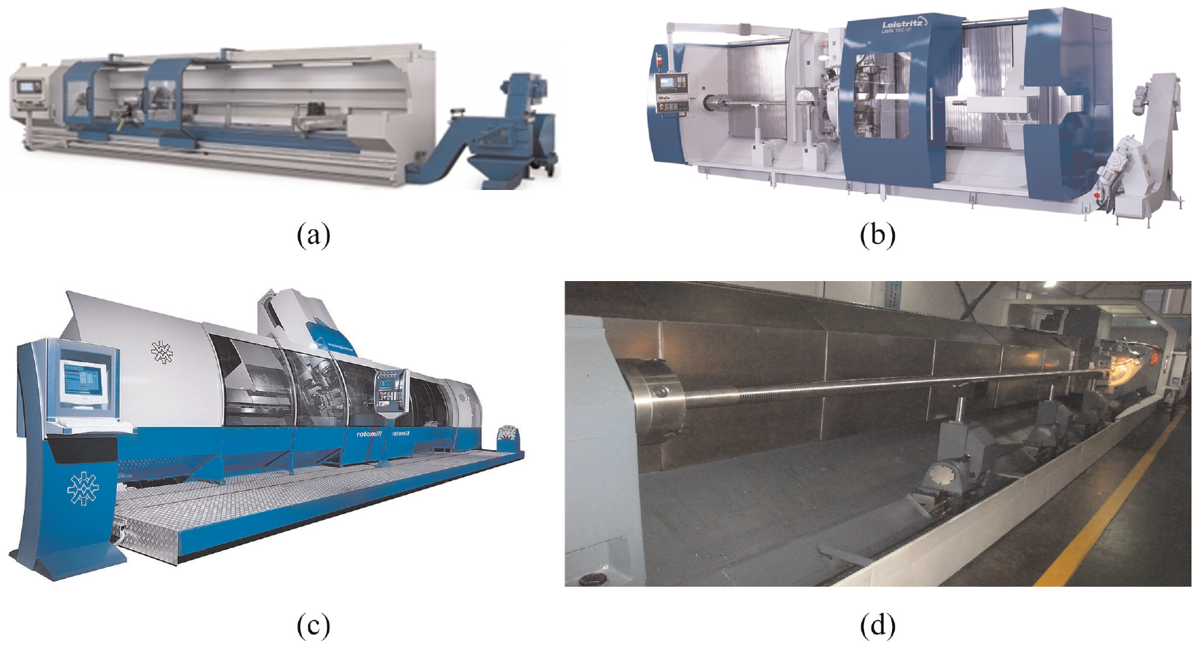
Machines for machining large-shaft components: (a) WM 250-8000 developed by Burgsmüller Company, (b) LWN300HP developed by Lerstritz Company, (c) WM 1000 developed by Weingartner Maschinenba Company, and (d) HJ092×80 developed by Hanjing Company.
Mobile machine equipment
If the size of components has greatly exceeded the machining range of existing equipment, and the development of large-scale specialized machining equipment has extremely high costs and low utilization rates, resulting in resource waste and a sharp increase in production costs. In recent years, the mobile machining robots have been increasingly applied in machining large components.37,38 The emergence of mobile machining methods has overcome the shortcomings of traditional machining equipment, expanded the workspace and improved efficiency, which made the entire production system more flexible.39–41 The mobile robot system with mobile platform, serial mechanical arm and end operator is often used in non-contact or small contact force working conditions, such as polishing, spraying, welding, grasping.42,43 In addition, the parallel/hybrid robots44,45 are also developed with its compact structure and light weight, which has the characteristics of re-configurable, high dynamic response, and low mobile mass. Thus, the parallel robots can achieve multi axis motion and have high stiffness to withstand large loads. They can be used as cutting execution units for mobile machining equipment. 46 Feng et al. 47 developed the blade grinding and polishing system using rectilinear orbit to move. By taking into account both kinematics and stiffness performance, Fan et al. 48 proposed a reference position optimization method to accurately find the optimal reference position in machining large complex components. Tao et al. 49 used the screw theory to analyze the motion of mobile robot, and conducted the experiments on machining task for a large-scale wind turbine blade. For little manual intervention and guaranteeing the synchronization performance of the machining system, Zhao et al. 50 used distributed coordination control to link multiple robots as a cluster system. Christian et al. 40 presented a mobile robotic system for machining large aircraft components. It fulfilled the high demands and tolerances in aircraft machining.
Machining methods
Traditional machining methods
In improving the machining precision of large-scale components, Feng et al. 51 studied the error compensation for the gantry milling machine. Lin et al. 52 presented a real time path correction approach of industrial robots and experimented with significant improvement. Textron Aerostructures adopted the creep correcting process to correct the large structural component (Figure 4(a)). 53 Bennetts produced a large aircraft wing skin with length 33 m, width up to 2.8 m, and thickness ranging from 3 to 28 mm (Figure 4(b)). 54 Jiao et al. 55 applied a elliptical vibration cutting to process a large-size thin-walled part with diameter 240 mm, height 122 mm, and wall thickness 2 mm. Dominguez et al. 56 selected optimized strategy and parameters for milling large components. Shin et al. 57 elaborated the cutting strategy of large size stainless steel pipes with a larger outer diameter of 165 mm and a thickness of 7 mm (Figure 4(c)). Schmitt et al. 58 considered the gravitational effects of large components and compensated the deformation to fulfill the tolerance requirements.

Additionally, Xi et al. 59 calculated the grinding wheel setting offset and compensated the normal residual errors by numerical control. An 800-mm-diameter mirror was ground to verify the proposed compensation grinding method. Zhou et al. 60 verified the accuracy and reliability of the thermal error compensation models, and revealed the relationship between the thermal error and the temperature for large-scale CNC gear. Guo et al. 61 utilized response surface methodology to achieve the multi-optimization of surface roughness and cutting force with high desirability. Wang et al. 62 modeled an analytical approach to investigate the forming errors, including circularity error, scallop height, and surface roughness. Yan et al. 63 analyzed the theoretical machining error by dividing the scallop height into axial and cross-sectional errors. Merticaru et al. 64 optimized the machining parameters to obtain a high accuracy for a large screw.
Non-traditional machining methods
Besides the traditional machining methods, some non-conventional methods were also used for large components. As shown in Figure 4(d), Lim et al. 65 proposed a curved-layered printing to construct the large-scale component with. It used Curved Layered Fused Deposition Modeling (CLFDM) principle to generate a curved-layered printing path in additive machining. To fabricate a large scale part by additive machining, two different large scale printers were used by activating the depositing water among powders one layer at a time. 66 Wang et al. 67 proposed a method of metal fused-coating additive machining composite variable polarity tungsten inert gas to form the large-scale aluminum alloy component. Jia et al. 68 simulated a selective laser melting to predict the distortions of large structure. Xie et al. 69 applied a method of discrete deposition and segregated heat-treatment to fabricate the large-scale component. Yan et al. 70 optimized the electromagnetic incremental forming scheme to form the large thin-walled component.
Machining quality of large components
For the surface quality, Gautam et al. 71 studied the complete residual stress distribution in large components. Spence et al. 72 conducted a special study on the geometry and stress of large-scale structural components, considering the particularity of a large number of data collection. Valentini et al. 73 employed ring-core method for evaluating the residual stresses in the large-sized forged steel shaft (Figure 4(e)). The strain data were collected at three different locations with distance maintained to around 600 mm. As shown in Figure 4(f), Jimenez et al. 74 applied portable ultrasonic EMATs to study the residual stress fields of large rail wheel on the machining site. Song et al. 75 experimented on a large hot-rolled ring of 2219 Al-Cu alloy with a external diameter Φ5000 mm × internal diameter Φ4700 mm, and investigated the distribution laws of the residual stresses, hardness, and micro structure. Hashemzadeh et al. 76 developed finite element analysis to estimate the post-weld-induced distortions and residual stresses of large-scale stiffener panel with a length of 3360 mm and a width of 540 mm. For machining Large 2219 Al alloy rings, the effect of grain refinement, 77 warm rolling deformation, 78 axial cold-compression, 79 and deformation temperature 80 on microstructure were studied respectively.
Measuring the large components
The measurement is absolutely vital for large components. For the high-precision large-scale components, such as large bearings and gears, several quality features have to comply with tolerances in the range of 20–50 mm. As shown in Figure 5(a), Shang et al. 2 firstly conducted a comprehensive investigation on the 3D shape measurement methods of large-scale complex surfaces, including the basic principles, application scope, measurement instruments, and then discussed the tasks and challenges in the current methods, and finally provided potential solutions. Jin et al. 81 reviewed and summarized the monitoring methods of slewing bearings for large-scale wind turbine generator system (Figure 5(b)).

Testing methods for large components: (a) 3D shape measurement projection, 2 (b) monitoring the slewing bearings, 81 (c) rail detection system, 83 (d) key 3D point measurement, 84 (e) s mobile robotic measurement system, 87 (f) inline measurement of Fuselage, 58 (g) zero-clearance assembly measurement, 90 and (h) a flexible and accurate measurement method. 108
Developing measuring methods
Some measuring system were designed to fit the requirements of large components. Pisani et al. 82 introduced a intersecting plane technique to achieve a lower measurement uncertainty for a large component with 10 m × 10 m × 5 m. Li et al. 83 conducted a gravitational straightedge method to measure the flatness of large rail (Figure 5(c)). It has four laser sensors to measure the concrete profile parameters, and a laser profilometer to calculate the maximum difference. Compared to experimental data, the precision in repeatability was ±0.01 mm. Huang 84 applied a measuring camera to get multiple photos containing points of code marks and non-code marks of a large gas turbine (Figure 5(d)). Then the data of key 3D points were analyzed, and the best-fitting line of gas turbine surface were calculated. Liu and Zhang 85 presented condition monitoring methods of large-scale wind turbine bearings. Dale et al. 86 developed a multi-channel absolute interferometer to measure numerous lengths up to 20 m.
In addition, the compensation and optimization methods were also explored to obtain the high accuracy and efficiency. Yu et al. 87 proposed a compensation method and experimentally improved the measurement precision (Figure 5(e)). Schmitt et al. 58 optimized a large machine tool as a comparator to measure the geometry of large-scale devices during the machining process (Figure 5(f)). Lambinet and Sharif Khodaei 88 developed a monitoring platform with different sensor technologies, and demonstrated its reliability with optimized data acquisition. Fan et al. 89 measured and corrected the location between the cutting tool and the interface of large components. The measurement was verified feasible and effective. Deng et al. 90 presented a on-line correction and positional evaluation for the posture alignment of large components (Figure 5(g)). Uekita and Takaya 91 presented a condition monitoring technique for deep-hole drilling a high-precision large-scale component.
Advanced measuring methods
To ensure the quality, the advanced accurate measurement of large components is an important mean. 92 The large stroke coordinate measuring machine (CMM) worked in the way of direct measurement, and was used for measuring large components with high measuring accuracy and good stability.93–95 As an optical measurement technology, the laser radar method uses a laser beam to obtain the information of large components by carrying the information with amplitude, phase, and so on.96–98 Due to its flexibility and strong adaptability, the laser tracker utilizes the principle of laser interference to provide precise relative distance, and is suitable for detecting large components with small-batch.99–101 Additionally, the theodolite method is based on the principle of angle space intersection measurement, and realizes the identification, aiming, and tracking of the large components automatically.102–104 Lastly, the indoor GPS works with multiple base stations measurement networks, and each station scans with a line laser on the optical plane. 105
If components are too large to fit into conventional measuring devices, the mobile measurements are with more application. For the large component with size up to 5 m × 5 m × 5 m, Wendt et al. 106 designed a mobile three-dimensional measurements for on-site high-accurate inspection and calibration. Ghidary et al. 107 combined ultrasonic and infrared signals simultaneously to test the positioning error using a mobile robot for an area of 6 m × 4 m. Zhou et al. 108 proposed a flexible and accurate measurement method for large components (Figure 5(h)). It combined a laser tracker, a 3D scanner, and a mobile robot system. The experimental results demonstrated that the maximum and mean calibration errors were reduced by half. Wang et al. 109 proposed mobile robotic measurement system, and developed a high-accuracy point clouds alignment algorithm to improve the accuracy of large wind turbine blade.
Conclusion
The study summarized the characteristic of large board and shaft components. The machining and measurement were complex and difficult due to heavy tasks and high requirements. Some suggestions for large components were carried out.
(1) Analyzing the peculiarities for large-board and large-shaft components. For a large-board component, it is with their complex features and weak rigidity, and the deformation was mainly due to the clamping and residual stress. For a large-shaft component, the geometrical accuracy especially for high precision and efficiency should be firstly guaranteed.
(2) For machining, the high-end large machine equipment and clamping devices should be designed and developed for obtaining more high requirements. It is necessary to develop clamping devices that adapt to the structural characteristics. Interacting with weakly rigid large-board components, the actively suppresses vibration and online compensation for deformation errors could be optimized deeply during the process systems. Additionally, some non-conventional methods have became a increasing for machining the large components.
(3) The developing measuring methods could give directions for selecting the device or sensors. The advanced measuring methods also provide more options for different working conditions. Besides if the component’s size has greatly exceeded the range of the current equipment, the mobile equipment is recommended for both machining and measurement, and its high-precision detection technology should be developed for multiple mobile ones. The study has guiding significance for achieving the high-precision and efficiency machining and measurement for large components, which is a great need in related industries.
Footnotes
Handling Editor: Chenhui Liang
Declaration of conflicting interests
The author(s) declared no potential conflicts of interest with respect to the research, authorship, and/or publication of this article.
Funding
The author(s) disclosed receipt of the following financial support for the research, authorship, and/or publication of this article: This work was supported by the National Natural Science Foundation of China [grant number 51805243, 2018].