
Abstract
Continuous fibre reinforced polymer (CFRP) have a distinctive anisotropic character. In traditional 3D printing processes, deposition direction cannot be adjusted. As a result, the performance of CFRP parts is deficient in the fixed direction. To address the issue, this paper proposes a variable deposition direction (VDD) 3D printing process for CFRP. The process optimises the mechanical properties of the moulded part by adjusting the direction of deposition. The principles and processes of the VDD 3D printing are described in detail. Then, using the hollow cylinder as an example, a mathematical model of the variable deposition direction structure is developed, and subsequent simulations is conducted to evaluate its mechanical properties. In the experimental part, the composite material used has a fibre content of 20% and consists of PETG and carbon fibres. The VDD hollow cylindrical parts have been printed to verify the feasibility of the process. And performance testing experiments were carried out on a variety of test specimens of different structures with VDD. The results show that adjusting the deposition direction of the CFRP can greatly improve the tensile properties of hollow cylinder. The tensile properties of a suitable structure with VDD were improved by a factor of 69.4 compared to a single deposition direction structure. And the actual tensile situation is consistent with the simulation. To summarise, the proposed method can effectively solve the defects of the traditional process and optimise the mechanical properties of the moulded parts.
Keywords
Introduction
Continuous fibre reinforced polymer (CFRP) are widely used in aerospace, transport, medical and other important national industries for its light weight and high strength properties. 1 The traditional CFRP manufacturing process has long product development cycles and high costs due to the limitations of the moulding process, moulds and other factors. 2
With the gradual maturation of 3D printing technology, the types of materials3,4 and fields 5 to which 3D printing technology is applicable are becoming more extensive. The development of 3D printing technology for CFRP offers new technological solutions for mould-free rapid prototyping of CFRP. 6 A great deal of research has been done by scholars worldwide on 3D printing of CFRP. Ramesh et al. 7 and Ramesh and Niranjana 8 investigated the effect of various process parameters on the 3D printing of fibre-reinforced composites.Hou et al. have designed samples of variable stiffness structures and tested bending properties of the samples. Experimental results indicate that the flexural modulus and impact strength of a suitable variable stiffness structure are increased by 70% and 65% respectively compared to a homogeneous structure. 9 Wang et al. propose a method for planning print paths based on workpiece load distribution. They use a vector tracking algorithm to convert the part load distribution into a tensile and compressive stress path and plan the print path accordingly. 10 In the study of the relationship between printing speed and printing quality, Akhoundi et al. discovered the continuous glass fibre reinforced composite material’s maximum printing speed. And they improve overall printing efficiency by optimising speed when printing corners. 11 Li et al. 12 repaired CFRP laminates with an open hole by 3D printing patches, and the experimental results showed that this repair method could significantly improve the load-bearing capacity of the laminates.
During the FDM 3D printing of CFRP, the model is formed in layers along the Z-direction, with the layers bonded to each other by the substrate. As a result, the performance of the formed part in the Z-direction is determined by the strength of the substrate and the quality of the interlayer bond. 13 The formed parts not only fail to take advantage of CFRP, but also have short mechanical properties in fixed directions, showing significant anisotropy. To address this problem, Zhang et al. proposed a hybrid 3D printing method of polymer and CFRP. They enhanced the mechanical properties of the moulded parts by laying CFRP on the surface of the resin matrix, and verified the method using a pipe model as an example. 14 However, the main body of the moulded part is still deposited in a fixed direction and the weak interlayer properties still affect the mechanical properties of the moulded part when it is subjected to forces in this fixed direction. If the direction of deposition can be changed during the printing process, the anisotropy of the CFRP part can be adjusted according to the forces applied to the part and the anisotropy of the material. In this way, the mechanical properties of the CFRP part can be enhanced by avoiding weak interlayer properties being expressed in the direction of force on the moulded part.
In order to adjust the 3D printing deposition direction, the postures of the actuators need to change together in a coordinated manner, so research into multi-axis 3D printing is essential. Zhang et al. divided the model into voxel surface layers using unsupported as a constraint. And experiments with unsupported 3D printing of complex models have been completed by this method. 15 In contrast to voxel surface layering, Xu et al. 16 perform surface layering and unsupported path planning based on geodesic distance, which has superior accuracy and planning effectiveness. Luu et al. build a robotic 3D printing system controlled by the ROS system. The system uses a knowledge-based trajectory planning strategy to plan 3D printing paths. Results indicate that this method can increase printing efficiency by a factor of 1.5. 17 Zhang et al. 18 built a five-axis dual-jet printing platform to enhance the performance of printed parts by winding CFRP on the surface of a resin matrix and investigated the effect of different winding angles on the performance of sample parts. Yao et al. generate surface layers based on the surface of the model and then plan spatially continuous paths on the surface layers. It was shown that the mechanical properties of the parts could be significantly improved by this path planning method. 19
Direction of deposition is also a key factor in the mechanical properties of the moulded part. Kubalak et al. made samples with the forming direction at different angles to the force direction. The tensile properties of these samples were then tested. The results indicate that the angle between the forming direction and the force direction has a significant effect on the tensile properties of the samples. The sample with the angle of 90° shows a 153% increase in tensile strength compared to the sample with the angle of 0°. 20 Bin Ishak et al. used single deposition direction and (variable deposition direction) VDD to undertake 3D printing and performance testing on samples with three orientations. The findings demonstrate that altering the deposition direction can increase the elastic modulus, yield strength, and ultimate tensile strength of the samples with a vertical orientation by 6.1%, 13.6% and 6.2%, respectively. 21 Ezair et al. propose a path planning method by filling the volume with curves. In this way they have completed the printing of a spiral structure in the topological direction of inflammation. Analysis has indicated that this method is effective in improving the strength and surface quality of parts. 22
In summary, research has been carried out on CFRP, multi-axis 3D printing, Direction of deposition. The current research involving 3D printing in the direction of variable deposition is still using resin materials. Resin material does not have the continuity and anisotropy of continuous fibre reinforced polymers. Moreover, these researches focus on achieving unsupported printing of intricate objects and enhancing mechanical characteristics by in-plane path planning. Few studies have been carried out to optimise the mechanical properties of moulded parts by adjusting the direction of deposition.
Therefore, the purpose of this paper is to proposes a VDD 3D printing method for CFRP materials so that the mechanical properties of the moulded part can be optimised by adjusting the deposition direction during the printing process. The principles of the VDD 3D printing process for CFRP have been investigated. In this paper, a model of a hollow cylindrical part with VDD is established, and its mechanical properties are analysed theoretically and simulated. In addition, this paper completed 3D printing experiments of CFRP cylindrical parts with variable deposition direction using a multi-axis 3D printing platform to verify the feasibility of the method. And the corresponding samples have been designed and tested to verify the improvement of mechanical properties by the method.
Methodology
Platform and materials
A multi-axis FDM printer for CFRP printing was designed and built in our laboratory. The experimental platform consists of a forming platform with two additional rotating axes, a six-axis robot as the main actuator and a CFRP print head mounted on the robot, as shown in Figure 1(a). The print head has an exit diameter of 0.8 mm and is equipped with a shearing device for CFRP.

3D printing platform and materials for VDD process: (a) platform and (b) materials.
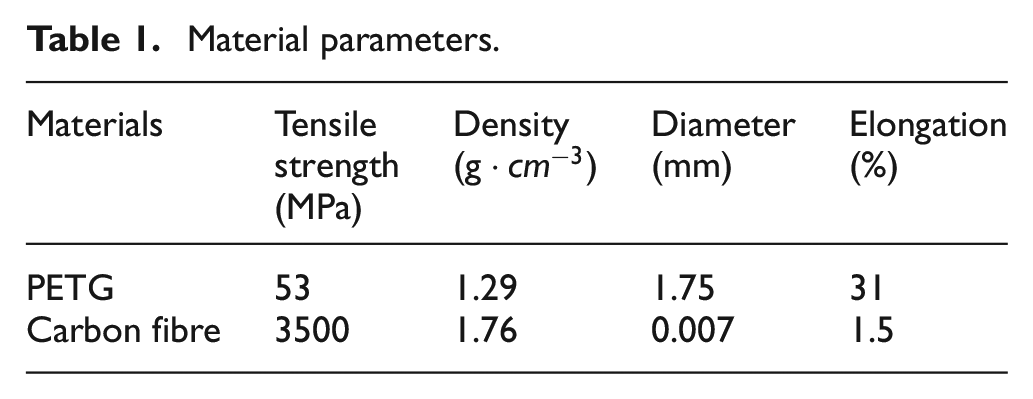
The material used for the experiments was laboratory prepared CFRP, as shown in Figure 1(b). The carbon fibres are supplied by Zhongfu Shenying Carbon Fibre Co., Ltd. and consist of 1000 carbon fibre filaments, with a single filament diameter of 0.007 mm. The resin substrate used is PETG and the finished CFRP product prepared has a diameter of 0.5 mm and therefore a fibre content of 20%. The parameters of the materials used are shown in Table 1.
Material parameters.
The VDD 3D printing process for CFRP
The process flow for VDD 3D printing applicable to CFRP is depicted in Figure 2. In order to achieve VDD 3D printing, the deposition direction of the model should be analysed in relation to the anisotropy of the CFRP and the forces on the part. The direction of deposition of the main body should be perpendicular to the direction of the force. According to the deposition direction, a VDD stratification plan can be carried out. In addition, the attitude of the platform and nozzle should be adjusted with the direction of deposition. In further, the coordinate relationships after platform attitude adjustment need to be discussed. Eventually, the print executable can be designed based on the analysis of the location relationships and the variable deposition layering plan.

Process flow chart for the VDD 3D printing of CFRP.
In a traditional continuous fibre-reinforced polymer 3D printing process, the part is divided by planar layers perpendicular to the Z-axis. The part is then formed in layers, stacked on top of each other until the forming is complete. The deposition direction does not need to be changed during the entire forming process. The orientation of the actuator is constant. In contrast, the VDD 3D printing method requires the attitude of the print head and printing platform to be adjusted according to the material anisotropy and the forces applied to the part. This method of deposition enhances the mechanical properties of the part while avoiding the failure of the print due to material shedding by gravity. Obviously a prerequisite for this process is a more flexible printing platform and print head.
Therefore, this study adopts a two-axis variable-position machine as the printing platform, and the printing head mounted on the end of a six-axis robot. The rotation and flipping of the printing platform, the attitude of the printing extrusion device, and the stacking direction of the printing layers are coordinated during the printing process. This achieves a VDD 3D printing process that combines the anisotropic characteristics of CFRP with the multi-degree-of-freedom motion execution mechanism, as shown in Figure 3.
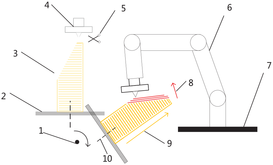
Schematic of VDD 3D printing. 1. Axis of platform reversal; 2. Printing platform; 3. Initial forming base; 4. Extruder head; 5. Shearing device; 6. Six-axis robot; 7. Robot base; 8. The direction of deposition after overturning; 9. Direction of deposition before overturning; 10. The rotation axis of the platform.
The process is as follows:
(1) The part base is formed in the vertical direction. This base prevents the print head from interfering with the platform during subsequent printing. Then, the initial part is deposited in the vertical direction and is printed on the base. The initial part also provides support for subsequent prints and prevents subsequent prints from collapsing and falling off.
(2) In consideration of the continuity of the fibres, the CFRP is sheared by a shearing device before the path jump or after each part has been formed. This prevents the unmoulded continuous fibre composite from pulling on the formed part.
(3) According to the anisotropy of the CFRP and the working forces on the part, the position of the forming platform is adjusted. By adjusting the attitude of the platform, the initial forming surface for subsequent 3D printing in the VDD can always be located in the right place in the robot’s forming space. This allows the subsequent printed part to be well supported while at the same time changing its deposition direction for the purpose of optimising the various anisotropic expressions of the material. The final result is the strengthening of the overall mechanical properties of the workpiece under working conditions.
(4) Robot controls the movement of the print head to the surface of the formed part for 3D printing. At this point the deposition direction changes.
(5) Steps 2, 3 and 4 are repeated until the part is fully formed and then the CFRP is cut by the shearing device.
In the VDD 3D printing process, the printing platform needs to adjust its attitude to adapt to the deposition direction. The adjustment causes a need to re-establish the positional relationship between the unformed part and the formed par. The size of the print base also needs to be designed in accordance with the positional relationship between the platform and the print head to avoid interference. Hence, it is necessary to analyse the positional relationship between the print head, the print platform, and the formed part during VDD 3D printing process.
Attitude analysis for VDD 3D printing
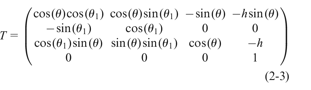
During VDD 3D printing process, the printing platform needs to be rotated or flipped. In the Gcode file obtained after slicing and path planning, the reference coordinate system of the coordinate points is based on the centre point of the printing platform when it is horizontal. In the course of printing, it is essential to maintain the relative position relationship between the formed part and the part to be formed in terms of spatial coordinates. Therefore, when the formed part rotates or flips with the platform, the coordinates of the part to be formed need to be transformed accordingly to match the position relationship with the formed part, as shown in Figure 4. The flipping axis of the platform is located directly below the platform due to the structural design of the two-axis variable-position machine. And it is parallel to the platform’s Y-axis. The distance between the flipping axis and the platform is H. Therefore the coordinate transformation process involves a specific order of transformations. First, a translational transformation is applied along the Z-axis to represent the flip axis position offset. Following that, a rotation transformation is performed around the Y-axis, representing the flipping of the platform. Then, a rotation transformation is applied around the Z-axis, representing the rotation of the platform. Lastly, another translation transformation is performed along the Z-axis for final adjustment. According to the above order, the transformation of the coordinates of the part to be formed can be expressed in matrix form as follows:


Schematic of platform attitude transformation.
The translation transformation matrix

It can be assumed that the flip angle is
The coordinates of the part to be formed can be expressed after transformation as follows:

Modelling and simulation of structures with VDD
Typical application object
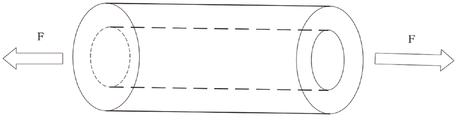
In engineering practice, cylindrical parts are widely used as components of load-bearing structures, such as the cable towers shown in Figure 5(a), which contain a large number of tubular truss structures as depicted in Figure 5(b). The tube truss structure can be split and simplified to a cylindrical model as shown in Figure 6. Based on the load-bearing characteristics of the truss structure, it can be assumed that the hollow cylinder is subjected to tensile forces along the axial direction under working conditions. In the traditional CFRP 3D printing process, cylindrical parts can only be formed in layers along the axial direction of the cylinder. The layers are bonded together by the base material of the composite. This also results in the mechanical properties along the axial direction being determined by the mechanical properties of the composite matrix and the quality of the bond between the layers. In other words, under conditions of axial tension, the main forces are carried by the polymeric base material between the layers of the cylindrical member. The performance advantages of CFRP cannot be exploited.
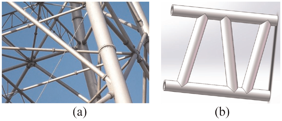
Application case of hollow cylinder parts: (a) the cable tower and (b) tube truss construction.
Schematic diagram of the hollow cylinder piece.
Different from conventional methods, the deposition direction of the cylindrical part can be adjusted according to the forces applied to the cylindrical part during the CFRP VDD 3D printing process. As the continuous fibre composite is deposited radially along the cylinder, the cylinder can withstand greater axial tension. Therefore a part of the cylinder can be deposited in the axial direction first. Then, based on the axially formed part, the remaining part of the cylinder is deposited radially along the cylinder. Through such variable deposition direction 3D printing method, the part formed along the radial direction can fully exploit the properties of CFRP at that working condition. The mechanical properties of the cylinder are substantially improved.
In this section, a mathematical model for a VDD 3D printing part is developed, using a cylindrical part as an example. The model diagram is shown in Figure 6. Its dimensional parameters are assumed to be 100 mm long, 36 mm inner diameter and 44 mm outer diameter. The mechanical properties of the cylindrical parts have been simulated and analysed by ABAQUS software. The simulation results indicate that the new process can improve the mechanical properties of cylindrical parts.
Mathematical model
In this section, a cylindrical part is assumed to be subjected to tensile forces under working conditions. The VDD 3D printing model is created using this cylinder as an example. Due to the anisotropic nature of CFRP, there are significant differences in its mechanical properties when deposited along different orientations. It can withstand greater tensile forces when deposited radially along the cylinder than axially. The cylinder model is thus created, consisting of a portion deposited along the axial direction and a portion deposited along the radial direction, as shown in Figure 8. This model is used as an example to analyse the stress-strain relationship for a CFRP cylinder manufactured by a VDD 3D printing process. The force conditions of the cylinder are assumed to be subjected to axial tensile forces only. And the effect of the VDD 3D printing process on the mechanical properties of the cylindrical parts is also discussed.
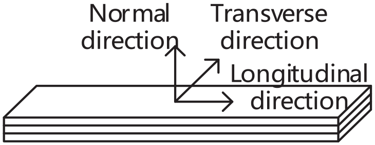
Figure 7 shows a model of a CFRP component. The component is deposited in the normal direction and the fibres are laid in the longitudinal direction. The relationship between stress and strain for this component can be described as follows:


Schematic diagram of CFRP sample.
In the above formula,
The layers of CFRP parts are bonded to each other by the base material. As the fibre content decreases, the normal tensile stress-strain relationship of the parts becomes closer to the performance of the base material. The interfacial properties begin to deteriorate sharply at fibre contents above 40%. 23 The CFRP used in this experiment has a fibre content of 20%. Therefore, under ideal conditions, the tensile stress-strain relationship of the base material is used to represent the normal tensile stress-strain relationship of the CFRP moulded part. This relationship can be expressed by the following equation. In the equation, E is the elastic modulus of the substrate.

Figure 8 depicts the cylinder formed by the VDD 3D printing. According to equations (2-5) and (2-8), the relationship between the total stress and the total strain during the axial tensile failure of the cylindrical part is expressed as follows:


Schematic diagram of VDD printed cylinder.
In the formula above, E is the critical fracture strain of the parts formed along the axial direction, and S1 and S2 are the cross-sectional areas of the parts formed along the radial direction and the parts formed along the axial direction, respectively. As the elongation at break is different between the two parts, they will not break at the same time. With this force condition, the part deposited along the radial direction will experience fracture as a primary occurrence. Thus, the two parts jointly resist the tensile force before fracture occurs along the radially deposited part. After fracture of the radially deposited part, only the axially formed part will resist the tensile force.
In the case of
In the case of
Finite element model
In order to visually verify the mechanical property enhancement of the cylindrical parts, a finite element modelling was conducted using ABAQUS software. The modelling focused on the CFRP hollow cylindrical parts formed through the VDD 3D printing process. As shown in Figure 9, since the hollow cylinder is an axisymmetric model, its quarters are modelled and symmetry constraints are added as a finite element model. Such a modelling approach reduces the computational burden. The dimensions of the finite element model refer to the model dimensions in Figure 6.

Finite element model of cylinder: (a) loading and constraint and (b) meshing condition.
The hollow cylinder model is divided into two parts for modelling: the inner side formed along the axial direction and the outer side formed along the radial direction. During axial stretching, the performance of the inner side is mainly determined by the polymer matrix. Thus, the inner side is modelled as a solid model with PETG material parameters. The outer part is the printed CFRP deposited along the radial direction. The material properties are combined with practical experiments and references to relevant literature. 24 The finite element mesh parameters for this part need to be set according to the actual printing parameters. In the print parameters used, the print layer height is set to 0.2 mm. Therefore, in the grid parameters of the outer part, the grid thickness is set to 0.2. In addition, a thickness-free cohesive cell has been added between the inner and outer sections to simulate the bonding of the two parts.
In this simulation environment, the hollow cylinder is simulated in axial tension by adding constraints and loads. The specific constraint and load scenario is to add a fixed constraint at the bottom of the hollow cylinder and a 10 mm axial tensile displacement load at the top of the hollow cylinder.
Results and analysis of simulation
Figure 10 shows the stress-strain curve of a hollow cylinder during tension in the simulation environment. The stress-strain curve for a hollow cylinder deposited in variable directions during tension is shown in Figure 10(a). The stress-strain curve for a hollow cylinder deposited in a single direction during tension is shown in Figure 10(b). As can be seen from Figure 10, during tensile process, the maximum tensile force that a hollow cylindrical part printed in a VDD process can withstand is substantially higher compared to a hollow cylinder deposited in a single direction along the axial direction.

Tensile test simulation image: (a) the VDD image and (b) single direction deposition image.
The tensile properties of hollow cylinders with different percentages of deposited volume along the radial direction have been investigated in the simulation environment. The stress-strain curves for the four variable deposition direction cylinders with 25%, 50%, 75% and 100% deposition percentage along the radial direction are shown in Figure 10(a). In the case of hollow cylinders subjected to tensile forces, the weak interlayer properties have less influence on the part deposited along the radial direction, thus the performance advantages of the CFRP material can be better exploited in the part deposited along the radial direction. This can also be seen in Figure 10(a), the higher the volume share of the deposited part along the radial direction, the higher the maximum tensile stress that the hollow cylindrical part can withstand.
Experiments
Executive file design of the VDD 3D printing
This section uses the cylinder model as an example. Based on the theoretical analysis of co-ordinate transformations, the executive file has been designed. The model has been printed to verify the feasibility of the VDD 3D printing process. Based on previous 3D printing experience in the laboratory, the print process parameters are set as follows: print speed is set to 300 mm/min, print temperature is set to 230°C, print layer height is set to 0.2 mm and print line width is set to 1 mm. With such printing parameters, better printing results can be achieved.
In the Layered planning process of CFRP models for VDD 3D printing, the model should be divided into multiple parts according to the force conditions and deposition direction. And the divided parts are separately sliced and layered to enhance the mechanical properties under working conditions.
According to the analysis in Chapter 2.4, in the case of a hollow cylinder subjected to axial tension, the part of the cylinder deposited in the radial direction performs better than the part deposited in the radial direction. Therefore, the hollow cylinder part should be divided into axially deposited part and radially deposited part for VDD 3D printing process. And The volume share of the radially deposited part should be increased as much as possible. For this reason, the thickness of the deposited section along the axial direction is set at a minimum value of 1 mm, that is, the print line width. As shown in Figure 11(b), the red part is deposited in the radial direction of the cylinder and the yellow part is deposited in the axial direction of the cylinder.

Cylinder model stratification plan: (a) original model, (b) the partitioned model, (c) stratification of a portion deposited along the radial direction, (d) stratification of a portion deposited along the axial direction, (e) path of a portion deposited along the radial direction, and (f) path of a portion deposited along the axial direction.
Parts with different deposition directions require separate slicing and layering, as shown in Figure 11(c) and (d). The part deposited along the axial direction is depicted in Figure 11(c). This part should be separated into equal groups of cylindrical surface with the cylinder axis acting as the group’s axis, and the spacing should be equal to the printing height. The part deposited along the radial direction is depicted in Figure 11(c). It must be separated into torus groups that are equally spaced along the cylinder’s axis, and their spacing also should be equal to the printing height.
After the cylinder has been sliced in layers, the paths are planned for the cylindrical and circular layers as shown in Figure 11(e) and (f) respectively. In combination with the principle of avoiding jumps, the path planning of the cylindrical surface layer deposited along the radial direction is shown in Figure 11(e). The path is in the form of a straight line filling that covers the cylindrical surface. The path plan for the circular surface layer deposited along the axial direction is shown in Figure 11(f). The path is in the form of a loopback fill. The spacing between the straight lines and between the loops is the print line width.
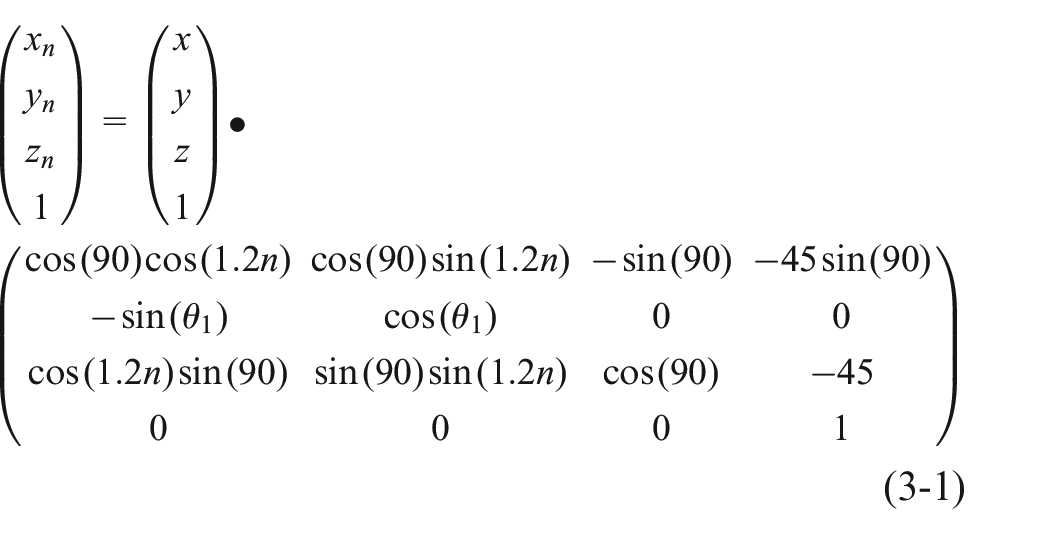
Before starting the radial deposition along the cylinder, the print platform needs to be flipped 90°. Then, after each straight path on a cylindrical surface, a 1.2° clockwise rotation is required so that the print path is always in a reasonable position in the robot’s workspace. Therefore, the coordinate transformation problem is present. Depending on the size of the real mechanical structure and the Angle necessary for printing, the parameters in equation (2-3) can be taken as h is 45,
Printing process
Figure 12 depicts the printing procedure. To prevent interference, the base is printed according to the height of the designed base. And the part deposited along the axial direction is deposited on the base. At the end of deposition in this direction, the composite is cut and the platform is flipped to change the direction of deposition and begin deposition in the radial direction along the cylinder. During the radial deposition, the printing platform needs to be constantly adjusted to ensure that the end of the robot is in the right position in the working space.

Process diagram of the VDD 3D printing: (a) printing the base, (b) depositing along the axial direction, (c) shearing the fibre, (d) fliping the platform, (e) depositing along the radial direction, and (f) end.
Figure 13 shows the hollow cylinder created during the experiment. Figure 13(a) shows a hollow cylinder manufactured by VDD 3D printing process. The lower end of the finished sample is the print base. It is formed by depositing first along the axial direction of the cylinder and then along the radial direction of the cylinder. A hollow cylinder printed in the single direction is shown in Figure 13(b). The depositing direction of the cylinder in Figure 13(b) is always along the axial direction of the cylinder.
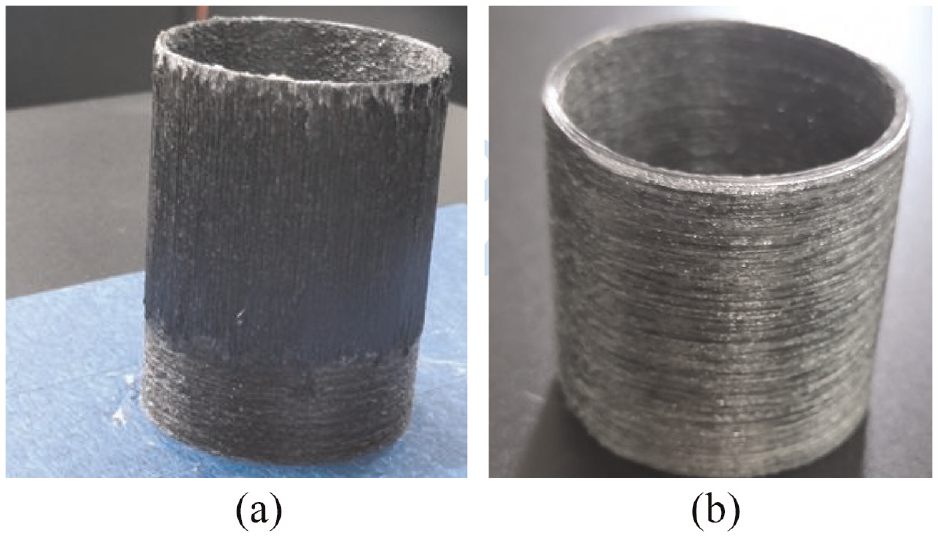
The printed sample: (a) hollow cylinder parts manufactured in the VDD 3D printing and (b) hollow cylinder parts manufactured in the traditional 3D printing.
Tensile test
According to ISO 6259-1:1997, to determine the tensile properties of a hollow cylinder, the tensile test pieces of a specified shape and size can be taken from the hollow cylinder, as shown in Figure 14(a). As the diameter of the hollow cylinder increases, the shape of the sample taken from it becomes closer to that of a standard test sample. Therefore, in this study, the intercepted samples were simplified to standard test specimens for tensile testing to determine the tensile properties of the hollow cylinders, as shown in Figure 14(b).

Tensile specimen fabrication: (a) splitting the specimen from the cylinder and (b) specimen simplification.
The tensile test specimens designed in this study are shown in Figure 15, with dimensions of 100 mm long, 20 mm wide and 4 mm thick. The arrows indicate the direction of deposition and x, y represent the thickness in the two deposition directions respectively.
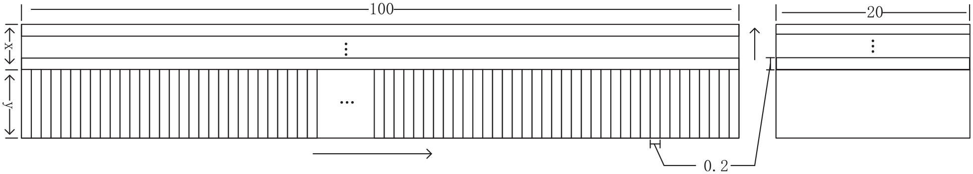
Tensile sample size and deposition direction.
The thicknesses of x and y of the samples used for testing are shown in Table 2, the printed test specimens are shown in Figure 16.
Dimensions of test specimens in variable deposition direction.


(a) Tensile specimens, (b) side view of sample No. 2, and (c) partial enlargement.
Results and discussion
Figure 17 shows that the stress varies with time. With increasing time, the specimen broke. We also chose the maximal testing stress as the reference object. The maximum stress values in Table 3 are the average of three tests. As shown in Table 3, specimens deposited entirely in the axial direction can withstand very little tensile stress, and those deposited entirely in the radial direction of the cylinder can withstand tensile stress the most. However, for parts such as cylinders, complete radial deposition during CFRP 3D printing is not suitable. Specimens 3D printed in VDD are able to withstand significantly higher maximum tensile stresses than those deposited along the axial direction. And as the volume share of the radially deposited part in the sample increases, the maximum tensile force it can withstand also increases. Radial75 samples can withstand 69.4 times higher maximum tensile stress than Axial samples deposited entirely in the axial direction.

Load image of tensile test.
Tensile test results.
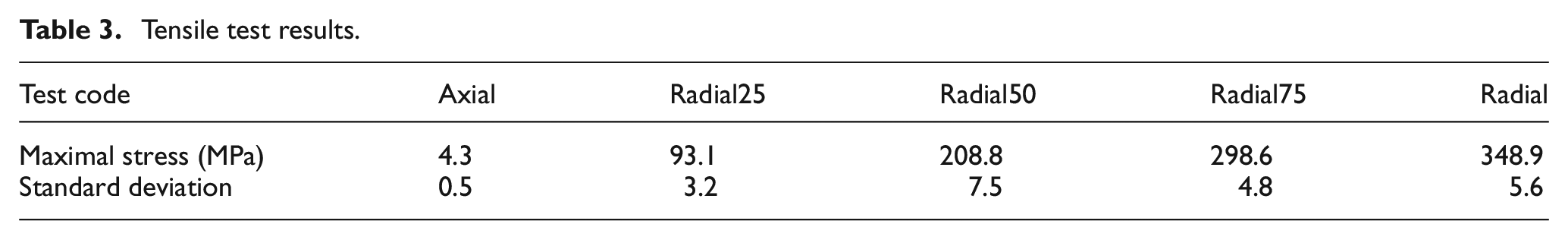
Figure 18 illustrates the variation of stress with strain in the simulated environment versus the actual test. The simulations and experiments in this figure are for a hollow cylinder with a volume share of 25% deposited along the radial direction. On the whole, the simulated stress change curve follows the same trend as the actual test stress change curve. The maximum tensile stress obtained from the simulation is greater than the actual measured maximum tensile stress. This is a result of the difference between the simulation and the actual experiment. In addition, the axially deposited parts of the simulation environment are assumed to be solid models and their tensile strengths are assumed to be those of the composite matrix. However, practical experiments have shown that the tensile strength of the deposited portion along the axial direction is much lower than that of the composite matrix, as seen in Figure 17.
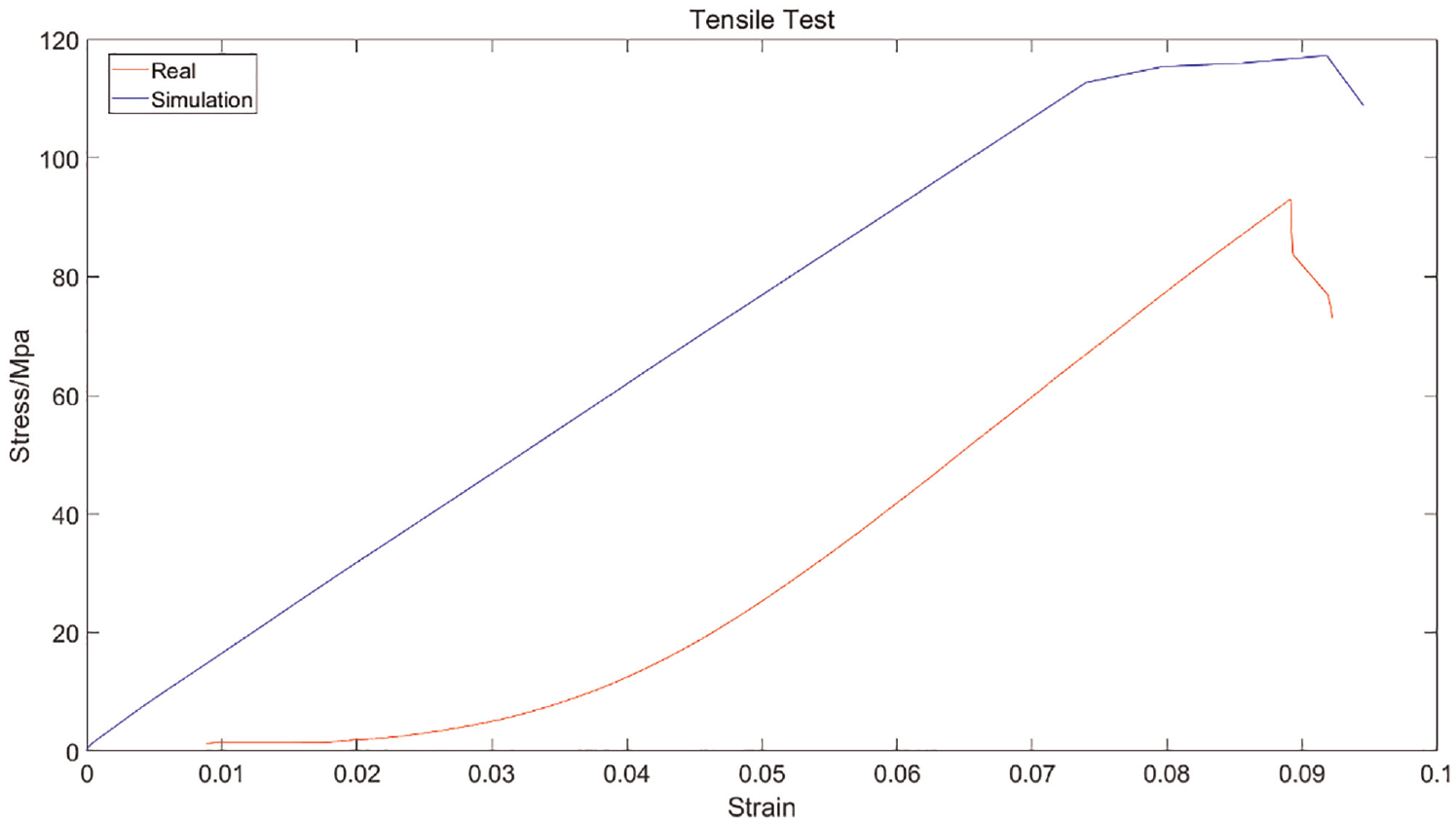
The simulation image and the real test image of the Radial25.
Conclusion
Given the weak mechanical properties of the CFRP material in the direction of deposition, this paper proposes a 3D printing method for CFRP with VDD. The VDD means that the deposition direction of the CFRP material is adjusted according to the working conditions of the part during the 3D printing process. As a result, the influence of weak interlayer properties is weakened and the mechanical properties of the part are optimised. Firstly, the process of CFRP 3D printing with VDD is described and the coordinate position relations during the printing process are analysed. Subsequently, mathematical models and simulation methods are investigated for CFRP structures with VDD, using a hollow cylinder as an example. Finally, a hollow cylinder has been printed in a variable deposition direction to verify the feasibility of the process. In addition, the tensile properties of the hollow cylinders are investigated. The tensile properties of the specimens can be significantly improved by 3D printing in a variable deposition direction. Compared to specimens deposited in a single deposition direction along the axial direction, the maximum stress is increased by a factor of 21.65, 48.4 and 69.4 for the VDD specimens deposited radially with a volume share of 25%, 50% and 75%, respectively. And the experimental results are consistent with the trend of the simulation results, so the established mathematical model and the simulation model have certain reference value.
The model built for the VDD structure is simple in terms of the forces and the direction of deposition, and the model is not always appropriate for complex cases. In addition, the stratification algorithm for deposition directions based on forces is not fully developed. Further work should revolve around these issues.
Footnotes
Handling Editor: Chenhui Liang
Declaration of conflicting interests
The author(s) declared no potential conflicts of interest with respect to the research, authorship, and/or publication of this article.
Funding
The author(s) received no financial support for the research, authorship, and/or publication of this article.