
Abstract
The 65 ml/r fuel pump proposed in this paper is a new type of large-displacement piston pump. The pump is of the roller plunger type construction. This structure enables the pump to have good performance even under high and variable speed conditions. Firstly, force analysis of this pump and establishment of mathematical model of pump mechanical efficiency. The influence of load pressure and speed on mechanical efficiency was obtained by numerical simulation through matlab. Then the prototype was designed and manufactured. The pump outlet pressure, outlet flow rate, and torque were measured on the test bench under various load pressure and speed, and mechanical efficiency of pump at various load pressure and speed was got. The experimental data and simulation are close. 65 ml/r fuel pump has a volumetric efficiency of 99% and a mechanical efficiency of 58.6% at a load pressure of 3 MPa and a speed of 1500 rpm. From experimental results, 65 ml/r fuel pump volumetric efficiency is high, but there is a problem of low mechanical efficiency. The piston of pump will be optimized for improved mechanical efficiency of pump. Then mechanical efficiency of the optimized pump is calculated and compared with mechanical efficiency before optimization. Results show that piston optimization will increase mechanical efficiency of pump.
Introduction
The fuel pump is a key component in the fuel system and its role is to provide hydraulic fluid to the power unit.1–3 And regardless of the changes in the control system of the power unit, fuel pumps are necessary in the control system. 4 Fuel pumps are used in a wide range of fields, such as aerospace, marine, and automotive. 5 The positive displacement fuel pumps used in ships can be classified as gear pumps and axial piston pumps. 6 The advantages of gear pumps are high flow rate and simple structure. However, the gears will make contact between the top of the teeth and the pump casing due to the unbalanced radial force, which will making the pump work less well. Gear pumps with high leakage and low volumetric efficiency.7,8 The piston fuel pump has a small leakage and high volumetric efficiency because the piston and the cylinder bore are cylindrical surfaces with high precision sliding surface fit. However, axial piston pumps are subjected to overturning torque from the piston during operation, which can lead to cylinder damage in severe cases.9–15 The mechanical efficiency of the axial piston pump is affected by three frictional pairs. These three frictional pairs are the flow distribution pairs, the piston pairs, and the slide shoe pairs.16,17
The following are the studies made by domestic and foreign scholars on the three friction pairs and mechanical efficiency of the piston pump. Professor Manring 18 proposed a new mathematical model for piston sub friction based on lubrication conditions, which agreed well with experiment, but did not consider the effect of piston state on the results. Bergada et al.19,20 solved the Reynolds equation for the oil film under piston tilt conditions, and the experimental results were close to the theoretical solution, but did not consider the effect produced by temperature. Gao et al. 21 used deviation analysis to select suitable test points, simplify and improve the model, and predict the efficiency of a piston pump quickly and accurately with an error within 1%, but the method fails at low load rates. Costa and Sepehri 22 obtained the overall efficiency of the pump and motor from the perspective of energy balance, which was previously obtained by separate construction of mechanical and volumetric efficiencies, which is a new way of building the overall efficiency and verifying it experimentally. Xue and Du 23 considered the effect of operating pressure, temperature, and air mixed in the oil on the volumetric efficiency in the mathematical model built, but have not yet verified its accuracy experimentally.
To balance the axial force of the piston pump as well as to eliminate the structural flow pulsation and increase the reliability of the pump. And to make the pump perform well under variable speed conditions and when starting with load. A new structure of roller piston pump was proposed by the team of Professor Ruan J at Zhejiang University of Technology. 24 This pump uses the reciprocating motion of the piston driven by the guide rail to change the size of the piston chamber to achieve oil suction and discharge, and the flow distribution function is achieved by the circumferential rotation of the flow distribution shaft. Eliminates the need for a distribution plate structure. Then, the pump was simplified in its mechanism. The pump replaces the sliding support of the traditional piston pump distributor with the cylinder block by rolling support of the guide rail to the roller. Rolling support makes the pump less dependent on the oil film, which can make pump still have good performance in high and variable speed conditions.
The 65 ml/r fuel pump is a large displacement piston pump with a roller piston structure. In this paper, a mathematical model of mechanical efficiency of 65 ml/r fuel pump will be built. The mechanical efficiency of the 65 ml/r fuel pump will be compared through experiments and simulations. The reasons of theoretical and experimental errors will be analyzed. And by optimizing the piston, we get the purpose of improving the mechanical efficiency of 65 ml/r fuel pump.
Pump structure and working principle
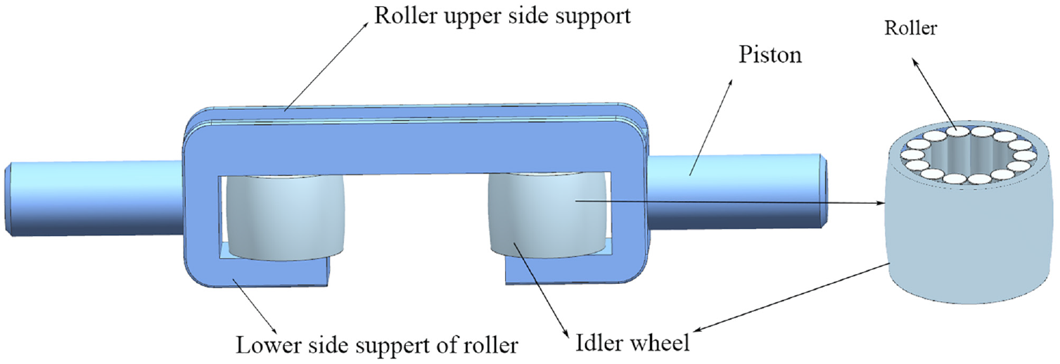
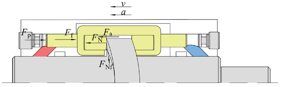
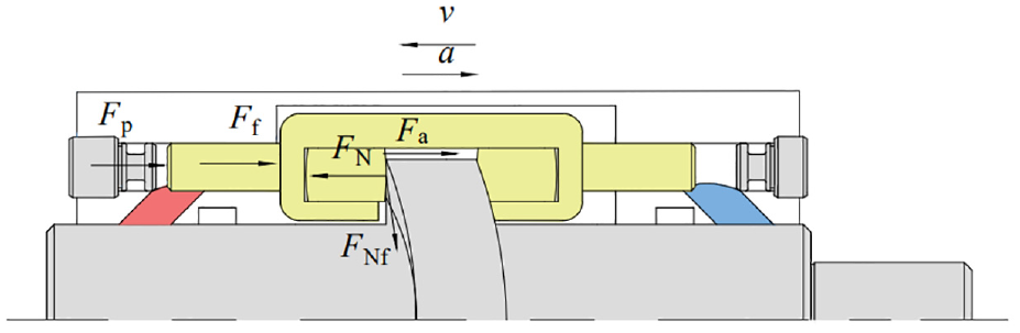
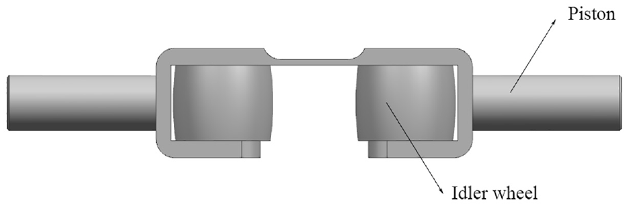
The interior of 65 ml/r fuel pump mainly consists of four parts: flow distribution shaft, cylinder block, piston, and guide rail, as shown in Figure 1. Inside distribution shaft, there are four through-holes for flow distribution; on the outside of the distribution shaft, there are eight flow distribution windows, four windows at the front and rear, and each through-hole communicates two flow distribution windows, one side is the high pressure flow distribution window and the other side is the low pressure flow distribution window. The small window is the low pressure distribution window. The big window is the high pressure distribution window, as shown in Figure 2. The curved surface of guideway is a law of motion with equal acceleration and deceleration. Eight pistons are evenly installed on the guide rail in the circumferential direction. Since the piston roller is close to guide rail, the motion law of the piston is the same as that of the guide rail, which is equal acceleration and deceleration motion. The motion trajectory between adjacent pistons is 45° apart. Meanwhile, the two cylinders are installed in opposite directions with the left and right sides of the pistons, and the inner side has an oil passage hole to communicate with piston chamber and shaft, and the outer side is equipped with a plug for sealing. The roller of 65 ml/r fuel pump is made of 14 cones arranged circumferentially along the inner wall of the idler wheel, as shown in Figure 3. During operation, the superimposed rollers fasten the inner wall of the roller shaft and idler pulley under load pressure.
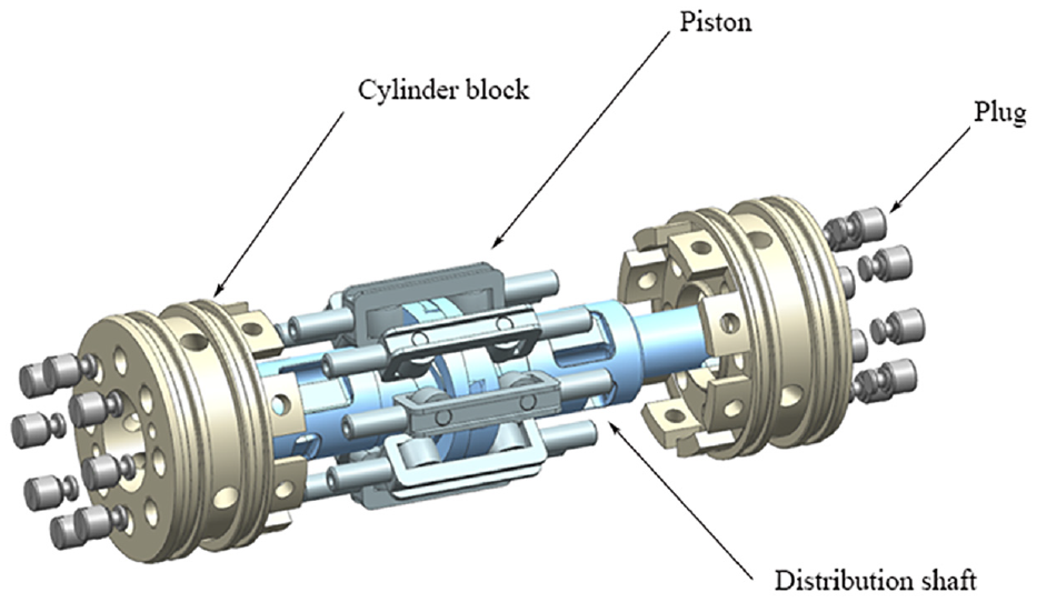
Explosion diagram of pump core.

Distribution shaft.
Piston.
The 65 ml/r fuel pump distributes the flow through the drive shaft. 65 ml/r fuel pump compared with the conventional piston pumps, the flow distribution plate structure is omitted. The structure of the pump has been greatly simplified. The guide rail is divided into two pieces with four wedges in the middle. Then the wedge will be under the action of centrifugal force will be propped up guide rail, so that it is close to the piston roller, so as to eliminate the gap and prevent the piston reciprocating movement and guide rail collision. 65 ml/r fuel pump is symmetrical construction, the two pistons with 180° phase difference have the same trajectory, and the two pistons with 90° phase difference have the opposite trajectory. So the inertia force of the pump is balanced. The role of the piston with 45° phase difference is to eliminate structural flow pulsation, but also makes the pump movement more smooth.
The fuel distribution process of 65 ml/r fuel pump is shown in Figure 4, in which the red area indicates high pressure oil and the blue area identifies low pressure oil. The motor drives the shaft and the guide rail for rotational movement through the transmission device. The piston idler wheel is restrained by the left and right sides of the guide rail. The piston starts to do reciprocating motion. The pump’s working volume cavity changes periodically to reach the purpose of oil suction and discharge.
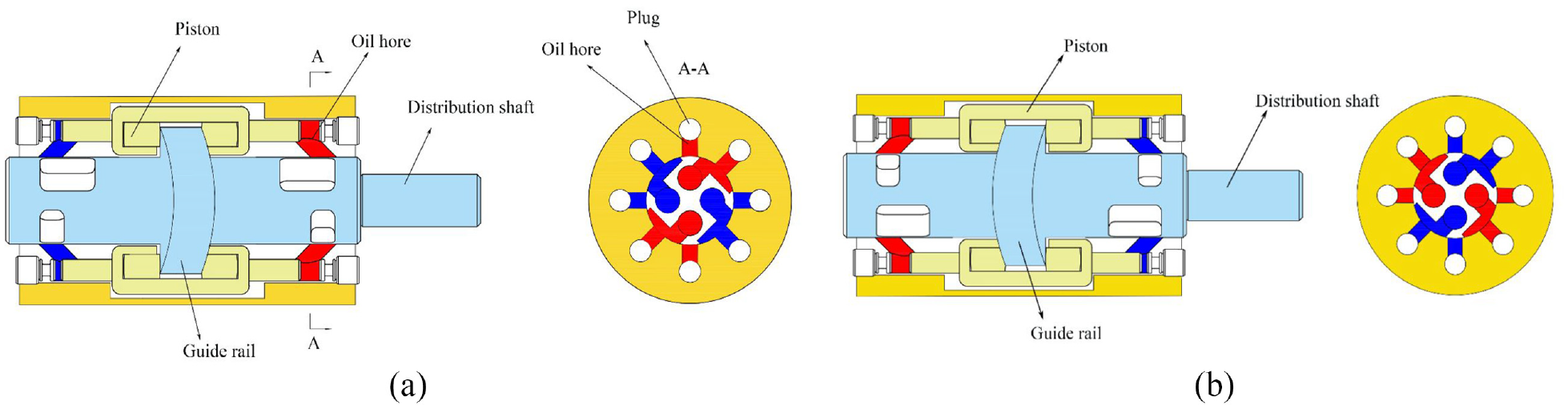
65 ml/r fuel pump core flow distribution process: (a) schematic diagram when rotation angle is 0° and (b) schematic diagram when rotation angle is 90°.
The position of the piston, the overlap area between the oil passage port of the cylinder and the flow distribution window of the flow distribution shaft, and the position of the contact point between the guide and the piston idler wheel will change with the rotation of the flow distribution shaft, and the position relationship of each moment is as follows: taking Figure 4(a) as the initial position, the piston idler wheel is in contact with the cam guide at the highest point of the surface, the volume of the right chamber is the minimal, the volume of the left chamber is the biggest, and the oil passage port corresponding to the two chambers and the flow distribution window Zero communication. From right to left, as the contact point between the guide and the idler wheel moves from the highest point to the lowest point, the piston moves from the right end to the left end, the volume of the right chamber increases from minimum to maximum, the flow distribution area between the flow distribution axis and the cylinder increases from zero to maximum and then decreases to zero, the volume of the right chamber of the piston increases and the volume of the left chamber of the piston decreases. Then the contact point of guide rail and idler wheel moves from the lowest point to the highest point, piston is moved to the right end from the left end, the mating area between the flow shaft and the cylinder body goes from zero to the maximum and then decreases to zero, the volume of the right chamber of the piston decreases and the volume of the left chamber of the piston increases and absorbs oil. At this time, piston completes a reciprocating motion, flow distribution shaft rotates 180°, piston unilaterally carries out a suction and discharge oil. So shaft rotates for 1 week, a single piston will finish sucking and discharging oil for four times. 65 ml/r fuel pump has eight pistons which can finish sucking and discharging oil for 32 times.
Mathematical model
The 65 ml/r fuel pump is driven by the motor to rotate the spindle and drive the piston through the guide rail for axial reciprocating motion. The motion pattern of the plunger is limited by the guide rail. Starting at the lowest end of rail, and the movement law of guide rail is as follows.


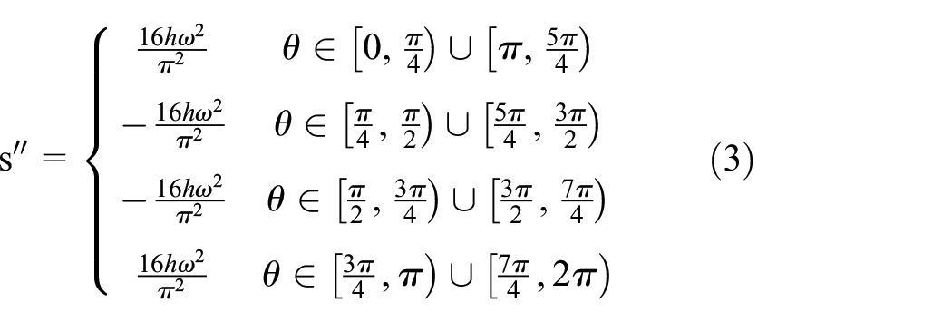
Where s is the displacement trajectory of piston. s′ is the movement speed of piston. s″ is the acceleration of piston. h is piston stroke. ω is the angular velocity when guide rail rotates. θ is the angle of rotation of guide.
The torque that needs to be provided when the 65 ml/r fuel pump works can be divided into three parts, which are the torque Ti provided by the guide rail to the piston, the oil shear torque Ts between shaft and cylinder block, and the churning loss torque Tc caused by the rotation of the guide rail in the oil.
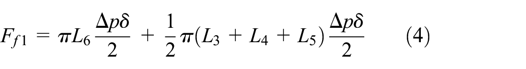
In the figure, L3 is the width from the edge of the valve orifice to the edge of the cylinder block, L4 is the width of the flow distribution orifice, L5 is the width from the valve orifice segment to the high-pressure groove, and L6 is the width from the high pressure slot to the end of cylinder block.
The 65 ml/r fuel pump’s distribution shaft is rotating while cylinder is fixed, and the gap between the distribution shaft and the cylinder is composed of relatively moving walls. Since the relative motion of the two walls, and because of the fluid visibility, shear force is generated between the moving walls and the fluid in the gap. At the same time, the existence of high and low pressure oil cavity makes the differential pressure flow between the distribution shaft and the cylinder body, as shown in Figure 5.

Cylinder inner expansion diagram.
In the axial direction, there is no relative movement between shaft and cylinder, so there is no shear flow in the axial direction, only differential pressure flow. The annular groove on the outlet side is the high pressure groove, oil in high pressure groove will flow to the outside of cylinder and low pressure chamber. The oil in the high pressure chamber will also flow to the outside of the cylinder through the gap.
In the circumferential direction, the oil flows from the high pressure chamber to the low pressure chamber through the clearance between the cylinder block and the distribution shaft. However, due to the circumferential arrangement of the high and low pressure chamber, the forces generated by the differential pressure flow can cancel each other numerically. Consider only the shear flow formed by the relative motion of the distribution shaft and the cylinder block.

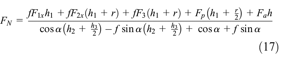
Guide rail rotation 0°–45°, the acceleration direction of the piston is the same as the velocity direction, and piston shows equal acceleration motion. The force situation is shown in Figure 6. Fa is the inertial force received by piston during movement. FN is the support force of guide rail on idler wheel. FNf is the frictional force between guideway and idler wheel. Fp is the pressure of high pressure chamber on piston. Ff is the resistance received by piston.

Force on the piston when rotated 0°–45°.
To determine the number of contact surfaces between both sides of the plunger and the cylinder bore wall. Create a simplified model of the plunger force in ansys. The established equivalent model is in Figure 7.

Piston simulation model diagram.
Where A is the pressure on the piston coming from the oil. C is the compression support simulating the support of the cylinder on the side of the piston. B, D is the compression support simulating the support of the rail on the idler wheel. E is the support force of the rail on the idler wheel. F is the fixed support simulating the fixed state of the cylinder.
The interaction force between the cylinder bore wall and the piston is expressed by the deformation amount using the principle of Hertz contact. The distortion of cylinder bore wall is shown in Figure 8. It can be seen that the left side of the cylinder bore wall has deformation on both sides, which means that the plunger has two contact surfaces. The right side of cylinder bore wall only has deformation on the lower side, which means that plunger has only one contact surface. This is because the guide rail has support force to the left idler wheel, while high pressure chamber has pressure to the left piston, and the deformation is not well transferred to the other side, resulting in the deformation of the left side of piston in Figure 8 is larger than the deformation of the right side.
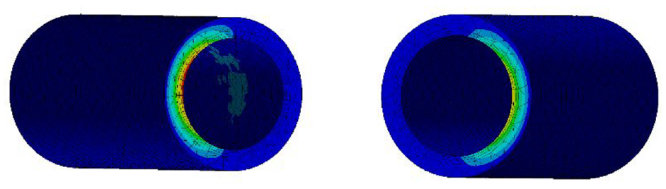
Cylinder bore wall deformation diagram.
The force analysis of the piston in this state is performed to solve the magnitude of the frictional force. As shown in Figure 9, piston is subjected to inertia force, gravity, support force of the cylinder on the piston and friction force, support force of the guide rail on the piston and friction force. The forces on the piston are analyzed to establish the equilibrium equation of the force system. The x-axis is the vertical side. y-axis is the vertical paper side. z-axis is the horizontal side.

Force diagram of the piston.
The equation of force balance in the x direction is:

The equation of force balance in the y direction is:

The force balance equation in the z direction is:

The balance equation of torque in x direction is:

The equilibrium equation of torque in y direction is:
The balance equation of torque in the z direction is:

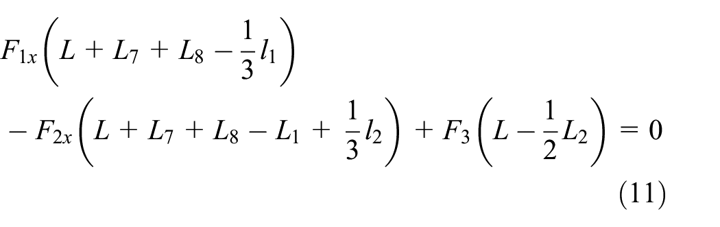
Where, F1, F2 are the lateral forces acting on cylinder on the side of high pressure chamber. F3 is the supporting force of low-pressure chamber side cylinder on piston. F1f, F2f are the lateral force F1, the friction force of F2. Fg is the gravity exerted by piston. L1, L2 is the length of plunger in the left and right end of cylinder respectively. L7 is the length from piston end and the center of idler wheel. L8 is half of the length from the roller axes on both sides. h1 is the thickness from the top side of the plunger to the top of the bracket. R is the radius of idler wheel. r is the radius of piston. R1 is the radius of the spindle. α is the roller pressure angle. f is the friction coefficient of cylinder wall face.
The lengths l1 and l2 of the lateral forces F1 and F2 acting on the left end of plunger.
The interval between the piston and cylinder bore is much smaller than the piston diameter and the length of the piston in the cylinder, so it can be assumed to be clearance-free sliding. Also assume that the sliding friction will not affect the distribution of the contact pressure between the piston and the cylinder. No relative rotation between plunger and cylinder. Then the contact length between the piston and cylinder bore wall according to the stress triangle similarity principle, l1, l2 length as shown in equations (13) and (14).


The action points of F1 and F2 are located at l1/3 and l2/3 far from the contact edge between the piston and the cylinder block respectively.
The lateral forces F1, F2 of the cylinder on the high pressure chamber side on the piston are solved by solving the force system balance equation to obtain the component forces F1x, F1y, F2x, and F2y on the x-axis, y-axis, and the support force FN of the guide on the piston, expressed by equations (15)–(19).


Where FNy is the component force of the rail-to-piston support force on the y-axis, and FNfy is the component force of the rail-to-piston friction force on the y-axis. It can be expressed as follows.


The lateral force F1, F2 of the high-pressure chamber side cylinder block against the piston can be calculated by F1x, F1y, F2x, and F2y.


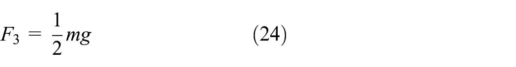
Assuming that the force at the right end of the piston is not transmitted to the left end of the piston and the left end of the piston only acts as a support, the support force F3 is given by the following formula.
The pressure Fp of the high-pressure chamber on the piston end face can be expressed by equation (25).

p is the pressure.
There is a drain port on the cylinder block. Therefore, the two cylinders are not filled with oil between them. The resistance Fpi to the axial movement has three main parts. The first part is the resistance of the piston by the oil when it is moving in the oil. The second part is due to the piston being supported by the guide rail, which has a circumferential force in the rotation process due to the support force of the guide rail on the piston. This force brings the piston side into contact with the cylinder transition section. The third part is the piston side and the cylinder transition section between the existence of clearance there is a shear flow resistance Fn. For plungers that are not immersed in oil. Only the plunger is in connection with the transition section generating friction force.


S 1 is the area of the bottom surface of the piston minus the area of the cross-section of the piston. S2 is the area of piston on the right side of rail. S3 is the area of piston side in contact with the cylinder. Fn is the force of cylinder on the side of plunger. v1 is the velocity of plunger when it moves axially. ρ is the fluid density. δ1 is the interval between the side of plunger and wall. μ is the dynamic viscosity of the oil.
Assume that the pressure of the piston side to the cylinder can be regarded as the idler wheel axis on its upper side of the end of the force on the cylinder. The force acting on the upper side of the idler wheel is equal to half of the support force of the guide to the piston. Therefore, Fn generates the frictional force Fnf can be indicated by formula 28.

When the guide rail rotates from 45° to 90°, the piston acceleration direction is opposite to the velocity direction, and the piston is in equal deceleration motion. The force analysis diagram is shown in Figure 10. The acceleration produces unilateral inertia force can be provided partly by the frictional force to the piston and the resistance to the axial motion, and partly by the guide rail. At this time, the support force FN of the guide rail on the piston can be expressed as equation (29).

Since the situation is the same when the guide is rotated from 0° to 45° and from 90° to 135°, only the force on the piston when the guide is rotated from 0° to 90° can be studied. The value of μf is negligible due to its small size. The inertial forces can be canceled by integrating the solution for rail rotation from 0° to 90°. So the inertia force of two adjacent pistons can be balanced, which is also the reason why 65 ml/r fuel pump can balance the axial inertia force. The average value of the support force on the piston roller during the rotation of the guide rail from 0° to 90° can be approximated by equation (30).

When the guide rail rotates from 0° to 45°, the contact state of both ends of plunger with cylinder block is shown in Figure 11. The presence of the gap between the two generates the oil shear force Fsh, as in equation (31).

Force on the piston when rotated 45°–90°.

The contact state between the two ends of the piston and the bore wall of the cylinder.
Frictional force Fnf on the side of the plunger. The resistance Fpi of the piston in axial motion and the friction between the piston and the bore wall of the cylinder.

The torque Ti of the guide rail to the piston subjected to friction.

The torque Ts generated by the differential pressure flow Ff1 and the shear flow Ff2.
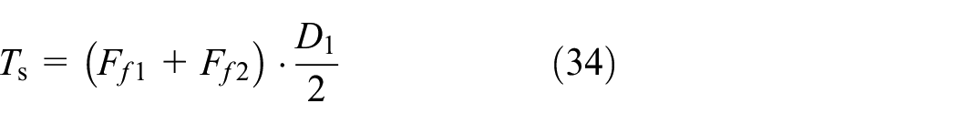
Where, D1 is the diameter of the circle where the contact point between the idler wheel and the guide rail is located.
The churning loss moment of the guideway can be obtained by fitting Fluent simulation Tc. 25

Summing these moments gives the total torque T for the 65 ml/r fuel pump 0° rotation to 90° input.

Where, T′ is pump output torque.
As a result, the mechanical efficiency of the 65 ml/r fuel pump can be expressed as equation (37).

Where VD is the displacement of 65 ml/r fuel pump and t90 is the time required to rotate the rail by 90°.
Mechanical efficiency simulation study
The mathematical model listed above is used as the basis. The effect of rotational speed and load pressure on the mechanical efficiency of the pump is studied by matlab. Specific parameters are shown in Table 1.
Simulation parameter settings.

The 65 ml/r fuel pump adopts the structure of a idler wheel piston pump with eight pistons arranged circumferentially. As the installation phase between two adjacent pistons differs by 45°, the movement law of two pistons also differs by 45°. The single plunger is rotated from 0° to 45° by the guide and the torque provided by the guide to it is increased. During the rotation of the guide rail from 45° to 90°, the torque provided by the guide rail to it is decreasing. This is due to the fact that in the process of 0°–45° of rail rotation, the acceleration is provided by the support force of the rail on the idler wheel, and the inertia force plays a hindering role. During the rotation of the rail from 45° to 90°, the acceleration is provided by the resistance of the piston movement and the reduction of the support force of the rail on the idler wheel, and the inertia force plays a role in helping the rotation.
For the whole 65 ml/r fuel pump. Eight pistons in the process of motion four for the speed up four for the speed down, and its output torque changes every 45° rotation for a cycle. The motion state is the same when the rail is rotating 0° and 45°. The plunger has the same number of plugs at the lowest, highest and middle of the rail, and the motion law is identical. Therefore, when studying the 65 ml/r fuel pump torque variation, it is only essential to research the variation in the process of guide rotation from 0° to 45°.
The oil shear resistance, piston friction resistance, and churning resistance of 65 ml/r fuel pump will increase with the speed. Under the same load pressure, rotational speed and torque are proportional. Under the same speed, the values of pressure and torque are proportional, as in Figure 12.

65 ml/r fuel pump input torque versus speed and load pressure.
The mechanical efficiency of the 65 ml/r fuel pump decreases due to the increase in speed. 65 ml/r fuel pump operation resistance also increases. At low pressure, the initial torque is a large percentage of the input torque. The load pressure rises. Mechanical efficiency of 65 ml/r fuel pump raises, as in Figure 13.
65 ml/r fuel pump mechanical efficiency as a function of speed and load pressure.
Experimental verification
Prototype of 65 ml/r fuel pump was built. Its substance is shown in Figure 14. 65 ml/r fuel pump configuration data are shown in Table 2.

65 ml/r fuel pump.
Table of main structural parameters of the pump under test.

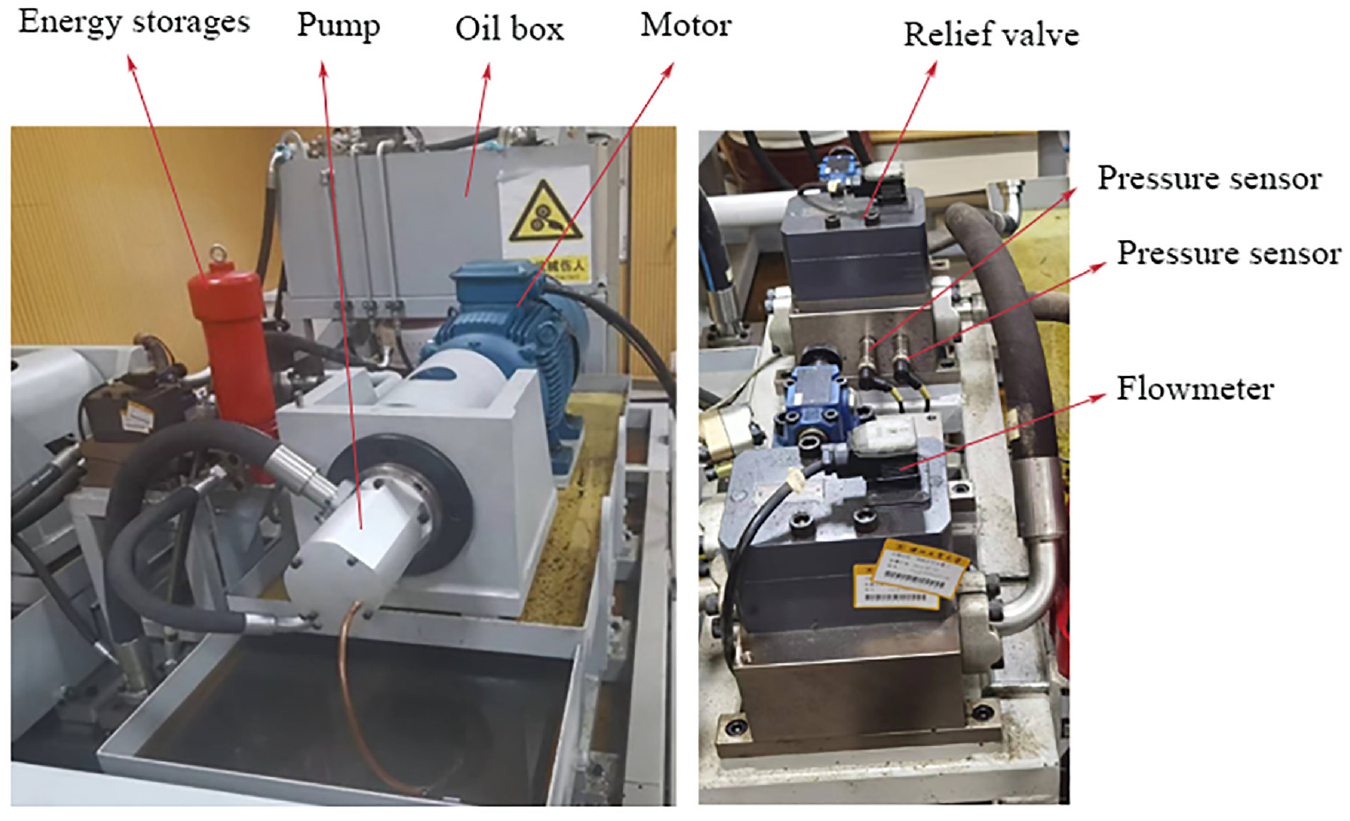
The schematic diagram of the designed test bench system is shown in Figure 15, which mainly composed by fuel tank, motor, pressure sensor, torque/speed sensor, flow meter, relief valve, and console. The pump under test is equipped with a torque speed sensor between the motor and the pump, which can measure the input torque and pump speed. The pump inlet and outlet are equipped with pressure sensors to measure the pressure coming out of the pump inlet and outlet. The pump outlet is also equipped with a flow meter to indicate the pump output flow. The test bench relies on the self-priming of the 65 ml/r fuel pump for fuel supply. The values of pressures, flows, speeds, and input torques can be read in the instrumentation on the console.

Test bench system schematic diagram.
Since the test stand has two parts of circuits, as shown in Figure 16, one circuit tests the pump performance and the other circuit tests the motor performance. When testing the pump performance it is necessary to cut off the left half of the motor circuit and return it to the tank through the relief valve. Therefore, only one part of the instrumentation on the console is functional, as shown in Figure 17.
65 ml/r fuel pump test stand.

Console.
The system tested the efficiency of 65 ml/r fuel pump at various speeds and load. Records output torque and flow rate at 1, 2, and 3 MPa at 500, 1000, and 1500 rpm of the pump. There was a lot of metal debris generated during the run-in process. This is due to the friction between the piston pairs and the friction between idler wheel and rollers on the lower side of the piston holder. This indicates that the piston and the cylinder bore wall and the idler wheel and the roller are in contact with each other and have a large friction force.
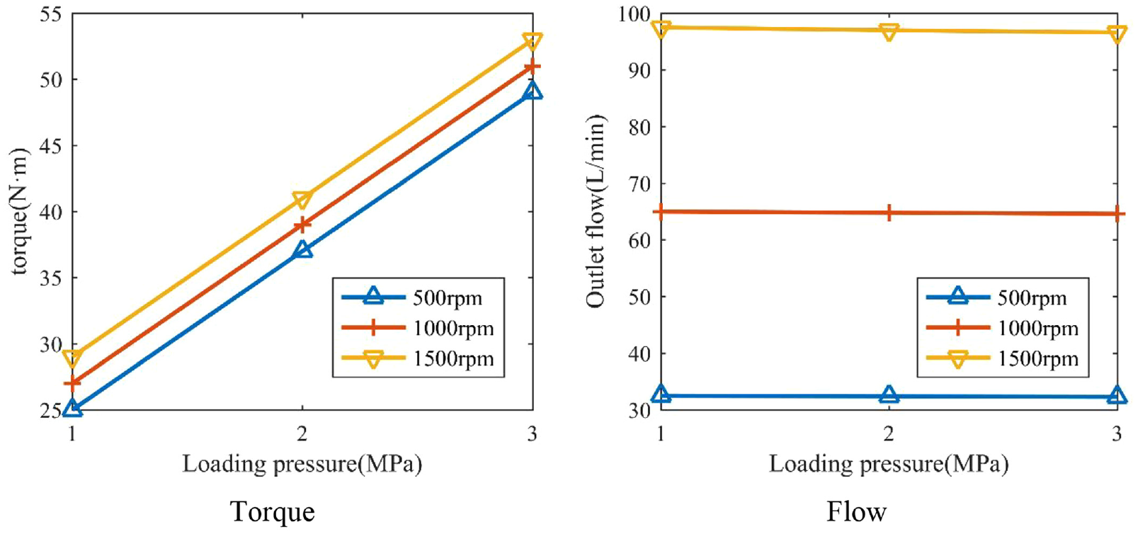
The instantaneous torque and flow rate of the 65 ml/r fuel pump at different load pressures and speeds were measured experimentally, as shown in Figure 18.
Actual measured instantaneous torque versus flow curve.
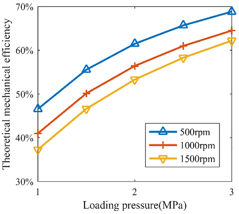
The experimental results of 65 ml/r fuel pump mechanical efficiency are shown in Figure 19. The experimental trend is in accordance with the trend of the theoretical value. However, there is still a gap for theoretical value and experimental value. At constant pressure, the input torque increases as the speed rises. At constant speed, the input torque increases as the pressure increases. It is also clear from the experimental results that the initial torque of 65 ml/r fuel pump is too high, resulting in a low mechanical efficiency of pump at low pressure. Due to the high viscosity of the oil. The pump leakage is low and the flow rate remains almost unchanged.

Comparison of experimental and theoretical mechanical efficiency at different speeds.
Three major factors for the gap between theory and experiment exist. One is because the calculation lacks the consideration of the friction between the idler wheel and the roller, the idler wheel and the roller on the lower end of the piston; two is because the piston as a whole in the case of continuous force bending the bottom of the piston leads to an increase in friction between the idler wheel and the roller on the lower end of the piston, and the deformation of the bottom of the piston leads to the hydraulic pressure and the support of the guide on the idler wheel is no longer aligned, will produce a x-axis torsional force, so that the force F1x, F2x increase in cylinder; three is due to the machining accuracy of the pump in the assembly there will be an initial torque.
In the theoretical calculation of 65 ml/r fuel pump the shear force of the oil, the friction between piston and cylinder is the most important factor affecting the mechanical efficiency of 65 ml/r fuel pump. The oil selected for the experiment is the common working medium of marine fuel pumps, which is hydraulic oil No. 46. The viscosity of this fluid is larger, so the shear force of the pump fluid is larger. And the plunger is subjected to a higher friction force due to more contact surfaces. The mechanical efficiency is 63.3% at 500 rpm, 60.9% at 1000 rpm, and 58.6% at 1500 rpm under a load pressure of 3 MPa. This is due to the rise in pump speed will lead to shear force of the oil and plunger is subject to increased friction

q is the flow rate. n is the speed. VD is the pump displacement.
At the same time, the outlet flow rate of 65 ml/r fuel pump is almost equal to the theoretical flow rate, and calculated by equation (38) to obtain the volumetric efficiency of more than 99%, as can be seen from the outlet flow rate Figure 19 of the pump. The pump leakage is very small and the oil flowing from the pump leakage port is much smaller than the pump leakage measured by the test bench. During the experiment, the amount of oil discharged from the pump leakage is very small. The leakage of the pump is mainly internal leak and there is almost no outside leak. Internal leakage mainly occurs between the shaft and the cylinders. There will be external leak between the piston and the cylinder. However, the plunger-to-hole wall clearance is too small as evidenced by the amount of leakage. The oil may not be able to fully lubricate the piston. When the piston is deformed, one end of the plunger will easily form two contact surfaces, and the contact surface increases leading to an rise in friction as well. To sum up, reducing the friction between piston and cylinder block is the most feasible way to improve the mechanical efficiency.
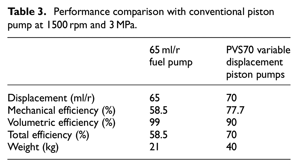
Table 3 shows the comparison of 65 ml/r fuel pumps with conventional piston pumps. Compared with the traditional piston pump, the 65 ml/r fuel pump is more integrated, has higher volumetric efficiency and higher power-to-weight ratio. However, the mechanical efficiency of this pump is currently low.
Performance comparison with conventional piston pump at 1500 rpm and 3 MPa.
Piston optimization
The mechanical efficiency of the pump is low, and a large amount of mechanical energy will turn into frictional heat during the operation of the pump, making the temperature of the pump rise rapidly. And the rise of temperature will make the oil viscosity drop. Oil viscosity drop will make the pump leakage increase, volumetric efficiency is reduced. At the same time, the low mechanical efficiency of the pump also indicates that the pump has a large wear, which will have an impact on the life of the pump.
The shear force of the oil and the friction to which the piston is subjected are the most important factors affecting the mechanical efficiency of the 65 ml/r fuel pump. The size of the shear force of the oil is related to the clearance between distribution shaft and cylinder, and the change of the clearance will cause the change of the volumetric efficiency. However, reducing friction can improve mechanical efficiency without affecting volumetric efficiency.
To reduce the friction force on the piston. A novel flexible plunger is proposed. What is expected to be achieved by this flexible piston structure is to reduce the friction force and also to reduce the weight of the 65 ml/r fuel pump. The mechanical efficiency and the work-to-weight ratio of the 65 ml/r fuel pump are further improved without reducing the volumetric efficiency.
Due to the same time only one side of the piston is subjected to the support force of the guide rail. And the original piston middle section thickness is larger, the force on the left end of the piston can not be transferred to the right end, the deformation of the piston in the case of force is concentrated in the left end, while the right end of the piston is less force, such as the left figure in Figure 20. By reducing the thickness of the middle section of the piston, the middle section of the piston can be bent more easily, so that the force can be transferred from one side to the other, increasing the value of F3 and decreasing the value of F2. Decrease the deformation of the left end of the piston in the left diagram of Figure 20 so that the acting force F1 is no longer generated.

Optimize the contact between the front and rear pistons and the cylinder wall.
The mass of the piston can be further reduced by adjusting the piston structure. As the strength of the roller shaft in the piston in the ansys static analysis is much greater than the force to be withstood. Therefore, the idler wheel shaft is changed to a hollow structure to reduce the mass of the pump. The thickness of the middle section of the plunger is reduced. The mass of the plunger also decreases greatly. It is meaningful to improve the work-to-weight ratio of the pump.
Build the flexible piston model as shown in Figure 21.
Flexible piston.
At that moment the force at the end of the plunger exists only F2, F3. Due to the x-axis direction by the smaller force can be approximated as F2, F3 equal to F2y, F3y, so from the formula 38 to solve the value of F2, F3.

Substituting the calculated results into the above, the mechanical efficiency of the piston pump when using a flexible piston can be obtained by calculating the mechanical efficiency before and after the piston optimization.
Figure 22 shows the variation curve of theoretical mechanical efficiency with load pressure at 500 rpm for 65 ml/r fuel pump with flexible piston and 65 ml/r fuel pump with normal piston. From the above graph. It can be seen that 65 ml/r fuel pump with flexible pistons will increase the mechanical efficiency by 5% over the original pump. Therefore, it is feasible to increase the mechanical efficiency of the 65 ml/r fuel pump by using a flexible piston.

Comparison of theoretical mechanical efficiency before and after piston optimization at 500 rpm.
Conclusions
A new type of large-displacement piston pump is proposed. Unlike the traditional axial piston pump whose drive mechanism uses oil film support, this pump uses rolling support. The flow distribution is realized through the rotation of the flow distribution shaft. 65 ml/r fuel pump does not need a separate flow dispensing structure. It eases the design of the pump. The roller type pump has a symmetrical design, so that the pump can achieve inertia force balance and no structural flow pulsation. Experimentally measured when the pump load pressure is 3 MPa, the speed is 500–1500 rpm, mechanical efficiency from high to low, varying from 63.3% to 58.5%, volumetric efficiency is almost constant 99%.
Develop a mathematical model of the mechanical efficiency of the 65 ml/r fuel pump. Simulation of piston contact state by ansys. On this basis, the mathematical model of mechanical efficiency of 65 ml/r fuel pump is established for 65 ml/r fuel pump and the way of rotating flow distribution of the distribution shaft. Analyze the effect of speed and load pressure on the variation of pump mechanical efficiency. The change curve of mechanical efficiency is obtained by matlab calculation. When the load pressure of the pump is constant, the mechanical efficiency decreases with the increase of the rotational speed; when the rotational speed of the pump is constant, the mechanical efficiency increases with the increase of the load pressure.
The experimental results are slightly lower than the simulation results. Reason one is the presence of friction within the piston assembly, friction between the wheel and roller and its upper and lower end surfaces, and friction between the wheel and roller. The second reason is the presence of the initial torque of the pump. Finally, a new type of flexible piston is proposed to improve the mechanical efficiency of the pump. This piston structure can reduce the frictional force on the plunger. A mathematical model of the force on the flexible piston was established, and the mechanical efficiency of the pump at 500 rpm was improved by 5% by calculation.
The pump can have better performance in variable speed conditions and with load start, and it can cope with more conditions in practical application. However, the internal structure of the pump is more complex and the machining cost is higher. A potential challenge with this design is that the pump can be difficult to maintain, as the highly integrated structure of the pump requires disassembly of the entire pump in the event of a failure.
Footnotes
Appendix
Handling Editor: Chenhui Liang
Declaration of conflicting interests
The author(s) declared no potential conflicts of interest with respect to the research, authorship, and/or publication of this article.
Funding
The author(s) received no financial support for the research, authorship, and/or publication of this article.