
Abstract
In order to solve the problem of torque-ripple in the control system of ship main propulsion motor controlled by direct torque control, this paper proposes a super-twisting sliding mode calculation method based on the traditional sliding mode controller, and designs the corresponding controller according to this method. The method is verified by Matlab/Simulink simulation tool. In the simulation waveform, the estimated speed of the super-twisting sliding mode control is almost consistent with the actual speed of the main propulsion motor, and the estimated rotor position is almost consistent with the actual rotor position of the motor, with small error. It is proved that this method has good practicability and effective feasibility in ship electric propulsion system, and provides theoretical reference for the design of ship electric propulsion system.
Introduction
The traditional diesel engine as the main propulsion device has the disadvantages of high noise, high pollution, poor comfort, and low handling performance, which makes the ship electric propulsion become the mainstream of the ship main propulsion device and is favored by the majority of ship owners. With the rapid development of power electronics technology, the speed regulation performance of AC motor can be comparable to that of DC motor, which makes ship electric propulsion widely favored by ship-owners all over the world. Among the newly built ships in the world, the proportion of electric propulsion ships is increasing. Due to the characteristics of large tonnage, high load capacity and limited cabin volume, the main propulsion motor for ships needs to have high reliability, large capacity, low speed, high torque, wide speed regulation range, and good speed regulation performance. Therefore, many ship electric propulsion systems choose the pod propulsion, and choose the synchronous motor with high power and small volume as the main propulsion motor.
Different from the electric vehicles sailing on the land, the ships sailing on the water face great resistance from the water, and the ship itself is large in volume and high in carrying capacity, which determines that the ship’s speed cannot be too high.
Since the ship often berths and leaves the wharf, enters and exits the narrow channel, and operates frequently, it is required that the speed of the main propulsion motor should not be too high, and the main propulsion motor can be operated frequently, and its speed-adjustment range should be relatively wide. In view of the above characteristics of ship main propulsion motor, direct torque control or vector control is widely used for the control of synchronous ship main propulsion motor. In Xu et al. 1 and Song et al., 2 the fuzzy controller is used to replace the traditional controller, and the fuzzy adaptive controller of torque, speed, and stator flux is designed. This control method has many advantages and can make the control system have good stability accuracy. In Li et al., 3 the combination of genetic algorithm and sliding mode control is applied to direct torque control, which greatly improves the response speed of the control system. However, because the ship is sailing on the water, the humidity in the cabin is high, which easily leads to inaccurate monitoring and even failure of sensors in the cabin. Therefore, the control mode without position sensor is also used to control the speed of the main propulsion motor. Some scholars use speed sensorless sliding mode observer to control the speed of main propulsion motor. 4 However, when the ship is sailing at low speed in the port waters or narrow waterways, because the speed of the main propulsion motor is low, the corresponding back EMF is low. At this time, it is inappropriate to use the back EMF method to estimate the rotor position.
Some scholars have specially studied the control mode of the main propulsion motor when the ship is sailing at low speed, and adopted the control method of high-frequency pulse vibration to realize the control of the main propulsion motor when the ship is sailing at low speed. There are few studies on the operating conditions of the marine electric main propulsion system in the high-speed, rated speed, the smooth transition of acceleration and deceleration process during the navigation of ships. During the voyage of the ship, the resistance on the propeller varies with factors such as wind, waves, ocean currents, tides, and waterways, which causes uncertainty in the load on the main propulsion motor shaft. The sliding mode control has the advantages of overcoming system uncertainty, strong robustness to disturbances, simple algorithm, and fast response speed. It is very suitable for controlling marine main propulsion motor.
In order to improve the comfort of the personnel on board, especially the passenger ship, and improve the maneuverability of the ship, this paper combines the traditional sliding mode control and makes corresponding improvements to make the acceleration process in the high-speed area more smooth and stable.
Modeling assumptions
This paper takes the hidden pole permanent magnet marine main propulsion motor as the research object. In order to simplify the mathematical model, the object of study is to be idealized. That is, the main propulsion motor is assumed to be an ideal motor, 5 which meets the following conditions.
The power supply voltage of stator winding is three-phase sinusoidal AC, and the influence of harmonic of power supply voltage is to be ignored.
The three-phase windings of the stator are ideally symmetrical, with an angle of 120° to each other.
Damping effect of permanent magnet is to be ignored, and the iron-loss of motor is to be ignored.
Magnetic saturation of motor core is to be ignored.
The theory of sliding mode variable structure
Sliding mode variable structure control (SMVSC) is a special kind of nonlinear control in essence, and its nonlinear performance is the discontinuity of control. 6 This control strategy is different from other control strategies in that the structure of the system is not fixed, but can be purposefully and continuously changed in the dynamic process according to the current state of the system (such as the deviation and its derivatives), which can force the system to move according to the state trajectory of the predetermined “sliding mode.”
Since the sliding mode can be designed independently, it is independent of the plant parameters and disturbances.7,8 Which makes the variable structure control have the advantages of fast response, have the advantages of insensitive to parameter changes and disturbances, have the advantages of no system on-line identification, and have the advantages of simple physical implementation. The disadvantage of this method is that when the state trajectory reaches the sliding surface, it is difficult to strictly slide along the sliding surface toward the equilibrium point, but it cross back and forth on both sides of the sliding surface, which will cause vibration, that is the ripple problem. 9 There is also a corresponding difference with the traditional PI control, that is, the control method has discontinuity, which is a switching characteristic that the system structure changes with time. The motion process of the sliding mode variable structure control system is shown in Figure 1.

Motion trajectory of the system.
In Figure 1, the character x represents the state variable of the system, and the motion process of the system includes AB segment and BC segment. On section AB, from time zero (t = 0), it gradually approaches s = 0 from s > 0, and then gradually leaves s = 0 to s < 0 beyond point B. The state variable x can be continuously adjusted by appropriate control mode to make it oscillate between s > 0 and s < 0 in BC stage and gradually approach s = 0. The approach process is called sliding mode, and the structure of the system is called sliding mode variable structure. 10
The assumed nonlinear control system is described as follows:

In equation (1), the character x represents the system state variable and the character u represents the control quantity, which meets following equation.

The sliding surface function is described as follows:

The corresponding control function is described as follows:
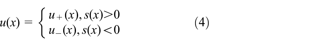
In equation (4), u+(x) ≠ u−(x), the following conditions is satisfied. 11
Existence of sliding mode.
The point moving outside s = 0 will converge to the origin within a certain time, that is,
The sliding mode motion is stable, and the dynamic performance of the control system meets the corresponding requirements.
Acquisition of speed and rotor position
According to Kirchhoff’s theorem, the mathematical model of voltage current relationship and electromagnetic torque of permanent magnet synchronous motor in two phase stationary coordinate system named α−β coordinate system can be obtained.

In equation (5), the character L represents the inductance of stator winding resistance of each phase, the characters uα and uβ respectively represent the stator voltage components in the two-phase stationary coordinate system. The characters iα and iβ respectively represent the stator current components in the two-phase stationary coordinate system, the characters eα and eβ respectively represent the back EMF components of the two-phase stationary coordinate system. The character Rs represents the stator resistance, the character Te represents the electromagnetic torque of the main propulsion motor, the character p represents the number of magnetic poles of the motor, the character L represents the inductance coefficient, the character ψf represents the flux chain of the permanent magnet on the rotor, the character |ψs| represents the amplitude of the stator flux, the character θi represents power angle, the character TL represents the load torque, the character B represents the coefficient of friction, and the character ω represents the mechanical angular velocity.
The mathematical model of the back EMF eα and eβ is described as follows:

In equation (6), the character ωr represents the rotor electric angular velocity, the character θr represents the electrical angle at which the rotor rotates. The character θr also reflects the position of the rotor, the character ωr also reflects the rotating speed of the rotating speed. If the back EMF eα and eβ can be measured, the information of θr and ωr can be easily obtained.

In equation (7), the character ωs represents the rotational electric angular velocity of the stator flux chain.
The mathematical model of the sliding mode observer of the current component on the two-phase stationary coordinate axis can be constructed from equation (5), and its expression is shown in equation (8).

In equation (8), the character K represents the amplification factor, the equation sign (x) represents the sign function. The characters
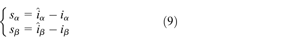
In sliding mode, sα is equal to sβ = 0, and are all equal to zero. The corresponding back EMF can be written as follows.

The discontinuous switching signal in ea and eβ can be filtered by a low-pass filter, which can be converted into equivalent continuous signal, and its back EMF is shown in equation (11).

In equation (11), the characters

In order to compensate for the phase-lag caused by the use of low-pass filters, the following methods are adopted in this paper.

In equation (13), the character

Super twisting algorithm
From equations (12) and (13), it can be seen that the calculated value of the rotor position angle is related to the arctangent function, the character
Overview of super-twisting algorithm
Suppose a dynamic system can be described as follows.
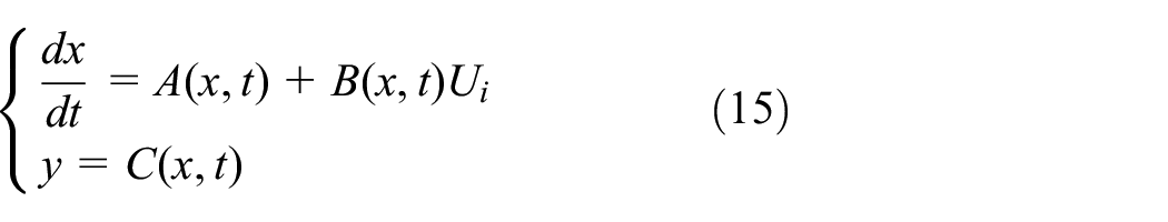
In equation (15), the character x represents the state quantity, the character Ui represents the input control, and character Y represents the output control; the characters A, B, and C represent the function of the state quantity x and time represented by character t. If the input control described as
The super-twisting control 14 is composed of the discontinuous function of sliding mode variable and the partial derivative continuous function of time, which can be described as follows.
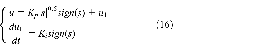
In equation (16), the characters Kp and Ki represent the amplification factor, the character s represents sliding-mode variable, and the character u1 represents intermediate variable. It can be seen from equation (16) that the algorithm does not have the differential of sliding mode variable s, which simplifies the complexity of the system and makes the control scheme easy to realize. In order to make the point converge effectively on the sliding surface during the movement and ensure good stability of the system, the amplification coefficients Kp and Ki should be large enough and meet the following conditions.

In equation (17), the coefficient Am ≥ |A|, BM ≥ B ≥ Bm, and the coefficient A and coefficient B should meet equation (18).

When both the coefficient Kp and the coefficient Ki in equation (16) are less than zero, the system will be converged within a limited time, it meets the expression
Sliding mode controller based on super twisting
Setting of sliding mode variable
In order to obtain an effective control signal, the amplitude of stator flux described as |ψs| and the electromagnetic torque described as Te of the motor are regarded as control objects. Combined with the super-twisting algorithm, torque sliding mode variable s1 and flux-amplitude sliding mode variable s2 are constructed.
Torque sliding mode variable
The torque slip modulus s1 is defined as the difference between the given value expressed as Te* of the torque and the actual value expressed as Te, 16 which can be described as follows

The first time derivative of the electromagnetic torque described as Te and the power angle described as θi in equation (5) can be easily obtained. Bring the first time derivative of power angle described as θi into equation (7), the following equation can be obtained.

The parameter |ψs| is assumed to be constant, and take another time derivative of the torque, the following equation can be obtained
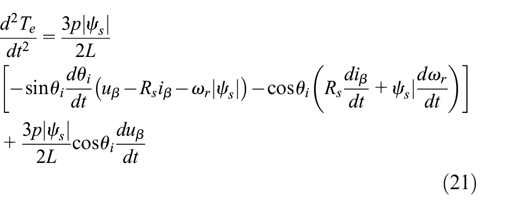
The parameters in equation (21) are limited, so the torque described as Te can be converged within a certain time, and the output control of the sliding mode variable is denoted as uα.
Flux chain sliding mode variable
The same as the definition of the torque sliding mode variable s1 the flux sliding mode variable is defined as the difference between the given value and the actual value of the stator flux amplitude, which can be described as follows.

Take another time derivative of the stator flux in equation (5), the following equation can be obtained

Each coefficient in equation (23) is a limited value, so the flux chain can converge within a certain time, and the control output of the sliding mode variable is denoted as uβ.
Rotational speed sliding mode variable
Take the motor state variables as follows,

In equation (24), the character ω* and the character ω represents the expected and actual rotational speed values of the motor, respectively. The integral sliding mode surface is built as follows.

In order to ensure the robustness of the system, the initial trajectory of the system should be on the sliding mode surface, which means
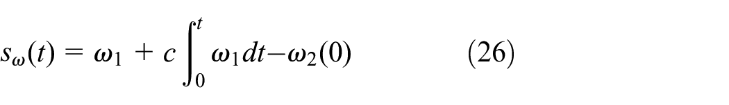
When t = 0,

In order to improve the dynamic quality of the system and compensate for its own shortcomings, a variable exponential approach law is adopted, the form is described as follows.

In equation (28), parameters a and b represent gains, respectively, which are greater than zero.
Design of controller
The difference between the given value and the actual value of the electromagnetic torque is taken as the sliding mode variable s1, and the difference between the given value and the actual value of the stator flux linkage is taken as the sliding mode variable s2. The stator voltages corresponding to the control output in the two-phase stationary coordinate system are described as uα and uβ. The super twisting sliding mode controller of its flux linkage and torque is described as follows.

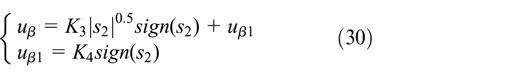
In equations (29) and (30), characters K1, K2, K3, and K4 respectively represent the amplification factor of the controller, and the controller is mainly composed of two parts. The first part mainly determines the dynamic response speed of the physical quantity controlled by the system, and the parameters K1 and K3 are adjustable. The latter part mainly determines the stability of the control quantity, and the corresponding parameters K2 and K4 are adjustable. According to the equations, the control block diagram is shown in Figure 2.
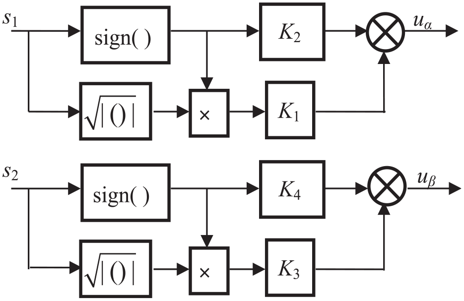
Controller based on super twisting algorithm.
The back EMF described as eα and eβ can be obtained by bring uα and uβ into equation (5).
Stability analysis
The stability judgment function can be obtained based on Lyapunov function,

Combining equation (28), the first derivative of the equation (31) can obtained.

In equation (32), only when S = 0, V/ = 0. It can be seen that the stability requirements are met and the designed sliding mode controller is available.
Simulation verification and analysis
According to equations (19)–(30) and Figure 2, the corresponding simulation module using MATLAB/Simulink simulation tools can be built as shown in Figure 3.

Simulation module based on Matlab.
During the simulation, the parameter settings are shown in Table 1
Simulation parameter setting.

In the whole control system, the second-order current closed loop and the third-order speed closed loop are adopted. In this paper, the motor is verified and analyzed under no-load and load conditions.
No-load state
In the no-load state, the initial value of the speed is set to 800 r/min, the speed suddenly increases to 1200 r/min at 0.05 s, and the motor load described as TL is set to zero. The corresponding waveform diagram is as follows.
Speed waveform
Figure 4 describes the speed waveform corresponding to the sudden change of speed under no-load condition, including the speed value of the super twisting sliding mode controller, described as “n-Smo”; and the speed of traditional vector control, described as “n-Pmsm,” and the reference value of the rotor speed of the main propulsion motor of the ship, described as “n-Reference.” From the change trend of the speed waveform, it can be seen that the speed transition process obtained from the super twisting sliding mode controller is smoother than traditional vector controller, and the transition time is about 0.01 s to reach the stable speed, indicating that the control system designed in this article has a fast response speed.
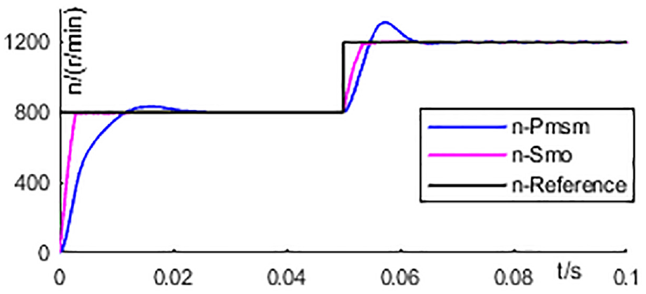
Speed waveform with sudden change of speed under no-load condition.
Rotor position
The tracking of rotor position under no-load condition is shown as in Figure 5.

Rotor position tracking with sudden change of speed under no-load condition.
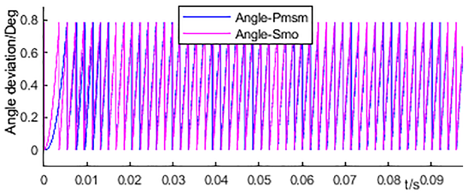
In Figure 5, “Angle-Pmsm” represents the rotor position angle difference of traditional vector control, and “Angle-Smo” represents the rotor position angle difference of the twisting sliding mode control. It can be seen from Figure 5 that when the motor starts and runs to a stable state, the two lines in the Figure 5 basically coincide, that is, the estimated rotor position of the super-twisting sliding mode control is basically consistent with the rotor position of the main propulsion motor. When the rotation speed changes abruptly at 0.05 s, there is a certain hysteresis between the estimated value of the rotor position obtained from the super-twisting sliding mode controller and the actual value of the rotor position obtained from the main propulsion motor. However, the hysteresis at this stage is not obvious, which indicates that the rotor position tracking effect of the control system is good, and the corresponding rotor position error is shown in Figure 6.

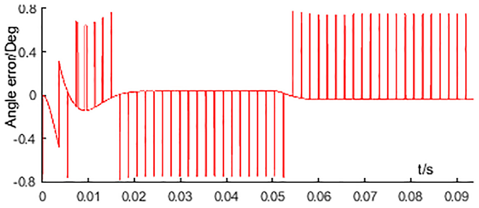
Rotor position error due to sudden change of speed under no-load condition.
It can be seen from Figure 6 that the position error value is between ±0.8°, and the error value in most time periods is about zero, which indicates that the super-twisting sliding mode controller has good performance in tracking the position of the ship’s main propulsion motor under no-load condition.
Torque
The torque waveform under no-load condition is shown in Figure 7. In the process of 0–0.01 s in Figure 7, the motor starts to stabilize, and the torque gradually decreases and stabilizes after increasing. The rotation speed increases abruptly at 0.05 s, the torque changes abruptly, and stabilizes after about 0.015 s. If the air resistance torque at no-load is ignored, that is, the torque at steady state is about zero, as shown in Figure 7.

Torque waveform of sudden speed change under no-load condition.
Three phase stator current
In case of sudden change of speed under no-load condition, the three-phase current waveform of the stator of the main propulsion motor of the ship is shown in Figure 8. Before the sudden change of speed, the stator current is stable, and the sudden increase of three-phase stator current due to the sudden increase of speed in no-load state. It can be seen from the current change curve that the system has good dynamic performance and fast response. After the speed is stable, the stator current decreases and tends to be stable. The stator current transition time is about 0.01 s. Compared with Figure 4, the current stability slightly lags behind the speed stability.
Stator current waveform with sudden change of speed under no-load condition.
Loaded state
When a ship is sailing at full speed at sea and meets sea wind or waves, the load torque on its propeller will change accordingly. In order to simulate this working condition, the speed is set at the rated speed of 1000 r/min, and the simulation waveform and analysis corresponding to the sudden load increase at 0.05 s are as follows.
Speed waveform
Figure 9 shows the speed waveform corresponding to sudden load changes under loaded conditions. In Figure 9, the speed value of the super twisting sliding mode controller is described as “n-Smo”; the speed of traditional vector control is described as “n-Pmsm,” and the reference value of the rotor speed of the main propulsion motor is described as “n-Reference.” In Figure 9, the rotation speed is stable at 1000 r/min before 0.05 s. When the load torque increases from 0 to 3 N m at 0.05 s, the rotation speed of the main propulsion motor first decreases and then gradually rises to a stable state, with a transition time of about 0.01 s. The waveform of the speed change process is smooth, and the system response speed is fast and the overshoot is small.
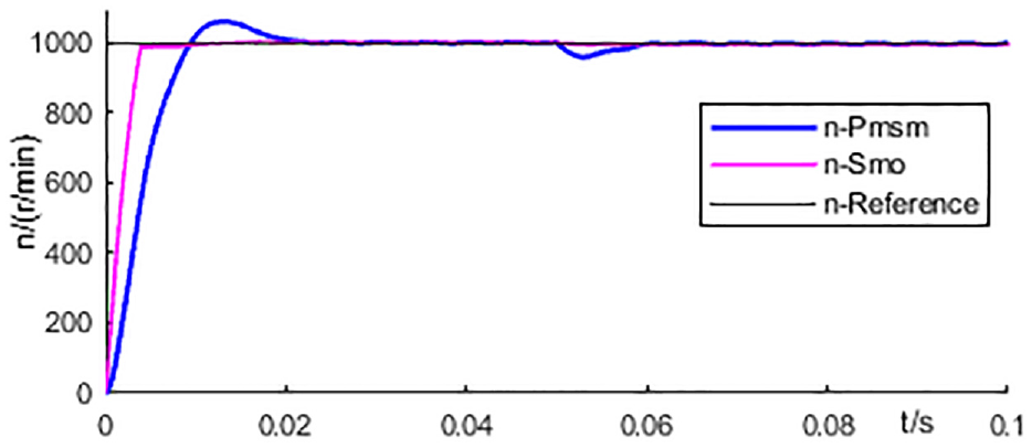
Speed waveform in case of sudden load change.
Rotor position
The rotor position tracking when the load suddenly increases at a constant speed is shown as Figure 10. The load torque increases from 0 to 3 N m at 0.05 s, there is a certain difference between the rotor position angle estimated by the super-twisting sliding mode controller and the actual rotor position angle of the main propulsion motor, the difference is between 0° and 0.8°, and has a certain hysteresis. The error between them is shown in Figure 11.
Rotor position tracking during sudden load change.
Rotor position error during sudden load change.
It can be seen from Figure 11 that the rotor position error is small, the difference is within ±0.8°, and the error is close to zero at most times. It shows that the super-twisting sliding mode controller has good performance in tracking the position of the main propulsion motor under load.
Torque waveform
The waveform corresponding to the sudden increase of load torque is shown in Figure 12. The torque suddenly increases at 0.055 s and stabilizes after about 0.005 s. The transient time of the response process is short, which indicates that the controller has good rapidity.

Torque waveform in case of sudden load change.
Stator current waveform
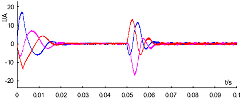
At the rated speed, the three-phase current waveform of the stator of the main propulsion motor of the ship corresponding to the sudden change of the load torque of 0.05 s is shown in Figure 13.

Stator current waveform under sudden load change.
Before the sudden change of the load torque, the stator current is stable. The load torque increases abruptly, which corresponds to the increase of the stator current, reaching a stable state in about 0.01 s. It can be seen from the current change curve that the system has good dynamic performance and fast response.
Conclusion
In order to overcome the ripple problem in the direct torque control, this paper introduces a super-twisting sliding mode controller based on the direct torque control of the ship’s main propulsion motor. The calculation method of super-twisting is described in detail, and the super-twisting sliding mode control scheme of ship main propulsion motor is designed. The simulation model is built by Matlab/Simulink simulation software. The simulation of the system under sudden change of rotational speed under no-load condition is conducted, the torque, stator current, and rotor position tracking under this operating condition are analyzed. The simulation of sudden load after stable operation under load condition is conducted, the speed, torque, stator current, and rotor position tracking under this condition are also analyzed. The simulation results of the two working conditions coincide with the theoretical analysis, which proves the rationality and practicality of the design of the super-twisting sliding mode controller in this paper, and can be effectively applied to the main propulsion system of ships.
Footnotes
Handling Editor: Chenhui Liang
Declaration of conflicting interests
The author(s) declared no potential conflicts of interest with respect to the research, authorship, and/or publication of this article.
Funding
The author(s) disclosed receipt of the following financial support for the research, authorship, and/or publication of this article: Supported by the Natural Science Foundation of Chongqing, China (Grant No. CSTB2022NSCQ-MSX1543) and the National Natural Science Foundation of China (Grant No.61273137).
Data availability
All data generated or analyzed during this study are included in this article, Data available on request from the authors. And the data that support the findings of this study are available from the corresponding author upon reasonable request.