
Abstract
RV reducers are commonly employed in precision transmissions, such as robot joints, owing to their multi-tooth contact characteristics, strong impact resistance, and low backlash. A finite element modal analysis of the RV reducer was conducted in this study to reduce the influence of RV vibration on the transmission performance and improve its transmission characteristics. The transmission characteristics are analyzed according to the transmission characteristics and principles. Combined with the theoretical basis of modal analysis, the finite element analysis method was used to analyze the main transmission components, and the natural frequencies and vibration modes of each main component were obtained. A modal analysis of the input shaft and cycloidal gear was performed, and the natural frequencies and vibration modes were obtained. The vibration patterns of the RV reducer, as well as the input shaft and cycloidal gear, were analyzed comprehensively. The distribution of each order frequency and deformation of the components can be determined by analyzing the frequency and array distribution of the components. An RV reducer transmission performance test platform was established to verify the accuracy of the simulation. Vibration signals under three different working conditions were collected, and the accuracy of the simulation was verified by analyzing the frequency signal, which provided important guidance for the design and optimization of the subsequent RV reducer.
Introduction
Manufacturing has reemerged as a prominent topic, as it undergoes its most significant transformation.1,2 The significant demand for intelligent manufacturing and low-carbon development is changing production and organizational models. 3 Based on network technology, the traditional factory has become more flexible, efficient, and responsive, eventually evolving into a smart factory that enables not only virtual manufacturing with cyber-physical systems but also customer-centric production and resource-efficient supply chains. Industrial robots are on the cusp of transforming manufacturing, introducing significant changes to the factory floor and perhaps to global competition, as they become smarter, more mobile, more collaborative, and more flexible.
While humans will continue to play an important role in the smart factory, robots and machines will assist and connect people. High-performance robots can conserve energy, decrease scrap, and work with a wide range of products, including small items like semiconductors and pharmaceuticals, as well as large items like LED chains, wind turbines, and other enormous items. 4 They could even be utilized instead of humans as manufacturing and testing equipment in hazardous and severe locations. Although an industrial robot is made up of several significant components such as mechanical (kinematic structure and reducer) and electronic (servo motor, driver, sensors, and controller), the precision reducer accounts for around 25% of the material cost and controls key performance aspects. 5 Geometry, kinematics, load, and accuracy are four technical parameters that can be used to describe an industrial robot. 6 Backlash, torsional stiffness, and torque density of reducers influence geometric factors like workspace, whereas backlash, torsional stiffness, and torque density of reducers govern kinematic parameters like acceleration and cycle time. Furthermore, the stiffness, moment, and torque load of high precision reducers determine the load characteristics of industrial robots. The precision and reproducibility of robots are linked to the accuracy and repeatability of reducers. A rotary vector reducer usually referred to as an RV reducer is a new type of two-stage closed planetary gear reducer developed based on cycloidal gears. RV reducers have been widely used in the fields of industrial robot joints, aerospace, machine tools, and so on, due to their advantages of high precision, rigidity, and efficiency. 7 It has a series of advantages such as a large deceleration ratio, small volume, light quantification, and good dynamic performance, so it has broad application prospects in the field of automation. The research of cycloidal drives to meet requirements in high-precision transmission areas, including cycloidal tooth profile design, modification methods, stress calculation,8,9 efficiency prediction, dynamic behaviors, and transmission error analysis, has received a great deal of attention. It is necessary to systematically study its transmission structure, vibration characteristics, and process optimization design, and carry out vibration tests, providing important guidance and practical value for engineering applications.10–13
Scholars have done a lot of research on RV reducers, the most important research contents are as follows: the tooth profile modification optimization of the cycloidal gear of the reducer,14–17 the finite element analysis of the dynamic performance,18–20 and the development of the new type structural reducer.21–23 Li et al. 24 proposed a meshing contact analysis approach for RV cycloidal-pin gear transmission using the RV cycloidal-pin gear pair transmission as an example. Chen and Yang 25 further explored the sensitivity of design parameters to the natural frequencies and modes of the driveline based on the work of some scholars. He made a modal analysis of the RV reducer’s crankshaft, cycloid wheel, and other main components in ANSYS. Jin et al. 26 established the virtual prototype of the RV reducer by CREO and ANSYS, and imported it into ADAMS for multi-body dynamics simulation. The reliability of the simulation method is verified by the experiment. Jiang 27 analyzed the crankshaft of the RV reducer in the ANSYS software through the setting of the free boundary support and the actual boundary support, then in the ADAMS software, simulate the transmission speed and contact stress of several key components, including the crankshaft, which provides important guidance for the follow-up dynamic performance research. Wang et al. 28 used the numerical analysis method to establish the modified cycloidal gear meshing efficiency model. The theoretical efficiency formula is deduced and the influence of modification quantity and short amplitude coefficient on efficiency parameters is analyzed. A new multi-tooth contact model and TE model of RV reducer have been proposed by Wang et al. 29 Li et al. 30 has presented a new approach for calculating meshing stiffness that considers the influence of tooth profile alteration and eccentricity error and determines the time-varying meshing parameters and load distribution of a cycloidal pin gear pair. To reduce the backlash caused by the modification of cycloidal gear, Lu et al. 31 proposed a modification method of cycloidal gear tooth profile based on deformation compensation. Based on equidistant and radial movement modification, the deformation of pin tooth under rated load is compensated. Li et al. 32 suggested a meshing contact analysis approach that takes manufacturing imperfections into account. The contact force calculated using the finite element method is compared to the experimental results of the RV reducer prototype to ensure that the proposed model is correct. In conclusion, the research conducted by the scholars mentioned above has significant impacts on the study of vibration in RV reducers. Through methods such as finite element analysis, modal analysis, and multi-body dynamics simulation, the vibration characteristics of RV reducers during the transmission process can be analyzed, and methods to reduce vibration through structural design and gear profile optimization can be explored. These research achievements provide both theoretical and practical foundations for the vibration control and optimization of RV reducers.
This paper first analyzes the transmission principle according to the structure of the RV reducer. Based on mechanical vibration theory, a three-dimensional solid model and the mathematical differential equation of the RV reducer are created. Subsequently, the RV reducer system is divided into grids based on its characteristics, and a finite element analysis model is established. Modal analysis is conducted by adding the corresponding contact conditions and applying constraints; the first 10 natural frequencies and corresponding vibration modes of the entire system, input shaft, and cycloidal gear in a period of motion are solved. A test platform for vibration characteristics was built, the vibration of the RV reducer under different working conditions was collected, and the test data were introduced into MATLAB software for processing. The reasons for the vibration of the RV reducer under different working conditions were analyzed, and a process optimization method suitable for improving the working performance of the reducer was developed.
Studying the vibration of the reducer can help to identify possible mechanical problems and vibration sources, and take corresponding measures to solve these problems. Modal experiments can help us determine the natural frequency and vibration mode of the reducer, which is crucial for optimizing design and improving performance. In the design and manufacturing process of the reducer, modal analysis can help design engineers determine the best material selection, geometric structure, and assembly method to minimize vibration and noise. In actual operation, modal analysis can help us understand the actual working state of the reducer and predict possible faults. Therefore, by studying the vibration of the reducer and conducting modal experiments, we can better understand the performance and safety of the reducer and take necessary measures to ensure its stable operation in industrial production.
Analysis and modeling of vibration characteristics of RV reducer
Analysis of transmission characteristics of the RV reducer
As a new two-stage high-transmission-ratio device consisting of planetary and cycloidal gears, the RV reducer has a unique and compact structure, as shown in Figure 1(a). The first stage of partial transmission is the differential structure composed of the input shaft and planetary gear, that is, the involute planetary gear transmission mechanism at the high-speed shaft, and the second stage part is driven by the pin gear housing, cycloidal gear, pin gear, and crankshaft connecting them, as well as the closed structure of the planetary frame as the output tray, that is, the K-H-V cycloid pin gear reducer at the low-speed shaft.

Structure of the RV reducer: (a) cad model and (b) schematic of the mechanism.
As the overall structure of the RV reducer is complex, to facilitate the analysis of its transmission principle, we simplify the entire transmission mechanism as shown in Figure 1(b). The RV reducer parameters used in the study are listed in Table 1.
Main geometric parameters of the RV reducer.

The RV reducer is driven by an external driving motor to rotate the input shaft, and the input speed is transmitted to the planetary gear to complete the first stage of deceleration. When the speed of the input shaft is ns, to rotate the clockwise direction in a clockwise direction, the two symmetrical planetary gears around the shaft of the center gear are rotated; additionally, the planetary gear itself will rotate, the rotation direction is counterclockwise, and the rotation speed is the input component of the lower deceleration part. Because one end of the crankshaft is connected to the rotary bearing and cycloidal wheel, and the other end is connected to the spline and planetary gear, the rotational speed of the planetary gear can be transferred from the crankshaft to the cycloidal gear to form a parallel quadrangle drive with the eccentric motion of the cycloidal planetary gear. In this paper, the pin gear housing is fixed, and the cycloidal gear is engaged with the pin gear at this time; thus, the cycloidal gear moves around the axis of the pin gear, while the crankshaft drives the output end of the steel frame to reverse the clockwise direction rotation movement through a supporting bearing installed on it. Finally, the output mechanism can transfer the rotation speed of the cycloidal gear to the planetary frame at a transmission ratio of 1:1, as the output speed of the final reducer system is equal to the speed of the second stage and that of the cycloidal gear.
Theoretical basis of modal analysis
Modal analysis is primarily used to study the dynamic characteristics of mechanical structures and various parts, which is the most basic content in all structural dynamic analyses. Because the vibration response of the mechanical structure system to various internal and external dynamic loads primarily depends on its vibration characteristics, the modal analysis of the system should generally be completed before performing other dynamic analyses, which lays the foundation for time prediction and parameter control of other dynamic characteristics analyses such as transient dynamic and spectrum analyses. The finite element software ABAQUS was used to perform a modal analysis of the components and the entire RV reducer, and the natural frequency and vibration mode were determined, which are the basic vibration characteristics of the transmission structure. From the perspective of structural design, this provides a certain basis for the optimization of design parameters in the later stage, avoiding resonance or vibration at a specific frequency when operating and reducing mechanical vibration and noise.
The fundamental problem to be solved in modal the modal matrix composed of modal vectors of each order in the linear steady-state system as the transformation matrix and converting the physical coordinates in the vibration differential equation group into modal coordinates such that the coupled equations can be transformed into a set of independent equations described by modal parameters; each equation has only one single parameter. The modal parameters of the system can be obtained by solving the equation. Its essence is to solve the modal vector of the motion equation with finite degrees of freedom under the condition of no load and no damping, namely, the eigenvalues and eigenvectors of the vibration characteristics of the structural system. This analysis method is simple in terms of calculation and significantly shortens the calculation time, making it an effective method to study the inherent vibration characteristics of the system.
Based on the above modal analysis theory, the vibration differential equation of a multi-degree-of-freedom structural system is obtained under external excitation without neglecting damping.

where
Because damping has only a slight effect on the analysis of the vibration characteristics of the structural system, it can be ignored; therefore, the natural frequency and vibration mode of the system are generally solved based on the scenario without damping. Ignoring damping, when

When no external load is applied, the differential equation of the undamped free vibration of the system is

The free vibration of the system is considered a simple harmonic vibration form, and the general solution of equation (3) is

where, A represents the amplitude matrix,
By performing the derivative of equation (4) twice with respect to time, the acceleration equation of the generalized system is obtained as follows:

By substituting equations (3) and (4) into equation (5), the following formula can be obtained:

Equation (6) is a homogeneous linear algebraic system, which is vital in vibration theory. The amplitude matrix is unknown and the mass and stiffness matrices are known. According to the theory of linear algebra, if equation (6) has a nonzero solution, the value of its coefficient matrix determinant must be equal to zero.

Equation (7) is a characteristic equation of the free vibration equation (3), which is also known as the natural frequency equation. After the characteristic equation is expanded, an nth-order algebraic equation
Mathematically, this process of solving feature pairs (i.e. the collective names of eigenvalues and corresponding eigenvectors) is called the generalized eigenvalue problem.
When the mass matrix M is a positive definite and the stiffness matrix K is a positive definite or semi-positive definite, the eigenvalues obtained must be nonnegative real numbers, and the eigenvalues are not equal to each other. They are arranged in order from small to large:

Substituting
Three-dimensional modeling of the RV reducer
Using the effective geometric modeling kernel Parasolid and SolidWorks software as the platform, a 3D parametric solid model of the key parts was created based on the geometric parameters of the RV reducer provided in Table 1. A three-dimensional model of the simple and practical RV reducer was obtained by assembling each part, and the three-dimensional model of the RV reducer was properly simplified. Some of the material properties of the main transmission parts are listed in Table 2.
Material properties of the main parts.

Finite element modal analysis of the RV reducer
Modal analysis of the input shaft
The first six natural frequencies and vibration modes of the input shaft were calculated using operation modal analysis, as shown in Figure 2, and Table 3 provides a description of the vibration modes of the input shaft.
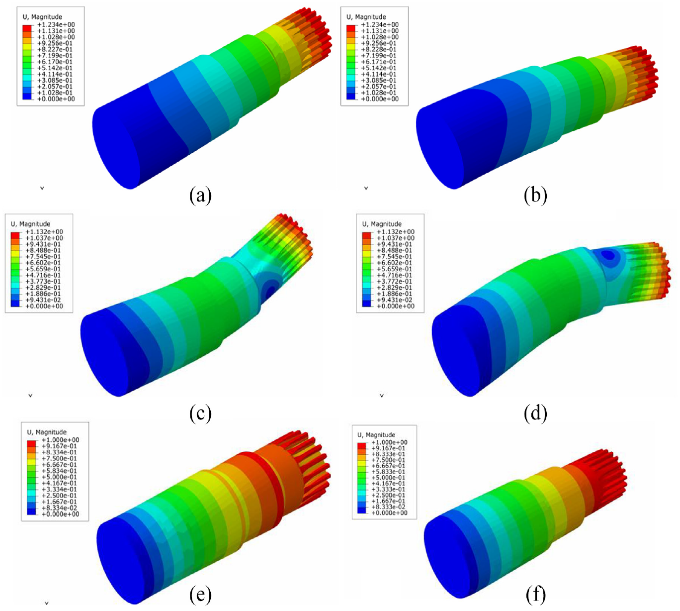
First six-order vibration mode of the input shaft: (a) first-order mode, (b) second-order mode, (c) third-order mode, (d) fourth-order mode, (e) fifth-order mode, and (f) sixth-order mode.
Vibration mode description of the input shaft.

From the observation and analysis of the vibration mode pattern of the input shaft can observe, the natural frequencies of the first and second-order were close, 819.32 and 819.4 Hz respectively. The main vibration modes were all slightly swinging in the Y direction, and the maximum stress is concentrated in the whole center gear. With the increase in natural frequency, the natural frequencies of the third and fourth orders were 3346.5 and 3346.9 Hz, respectively, the two order frequencies were similar in their vibration modes, the central part of the input shaft bent and were swinging in the direction of Y, and the stress concentration at the top of the center gear appears. In the fifth-order vibration mode pattern, the entire input shaft expands outward and the natural frequency was 3406.7 Hz, the amplitude of vibration was larger in the middle and upper parts of the input shaft, and there was a tendency to move along the center gear along the negative Z direction. The natural frequency of sixth-order vibration mode was 4788.5 Hz, the input shaft contracted in the middle part, and the stress value of the center gear was the greatest. We observed from the seventh, eighth, and tenth order vibration mode patterns that the modal vibration modes were primarily curved twists around the Z direction, and the amplitude of the vibration at the top meshing edge of the center gear was the largest, their natural frequencies being 7190.1, 7190.8, and 11,643 Hz, respectively. In the ninth order vibration mode pattern, the natural frequency of the input shaft was 7760 Hz, the maximum stress is concentrated on every contact tooth of the center gear, and the main performance was the twisting and rotation of the center gear around the Z direction.
The following conclusions can be drawn from the first to tenth order vibration modes of the input shaft: the stress concentration on the surface of the center gear is the most apparent, and the position of the maximum amplitude occurs here, such as in the third to fourth order and seventh to tenth order modes; the maximum stress is on the meshing contact tooth surface at the top of the center gear, and the vibration displacement is apparent. The middle part of the input shaft is also relatively weak, with external convex and internal shrinkage deformations, and even in the high-order mode, there is destructive wave distortion. Therefore, the structural parameters of the center gear and input shaft should be further optimized, and the stiffness of the middle part of the input shaft should be increased to improve its vibrational characteristics.
Modal analysis of the cycloidal gear
Similarly, the first six natural frequencies of the cycloidal gears were calculated using operation modal analysis, and the pattern and description of each vibration mode are shown in Figure 3 and Table 4, respectively.
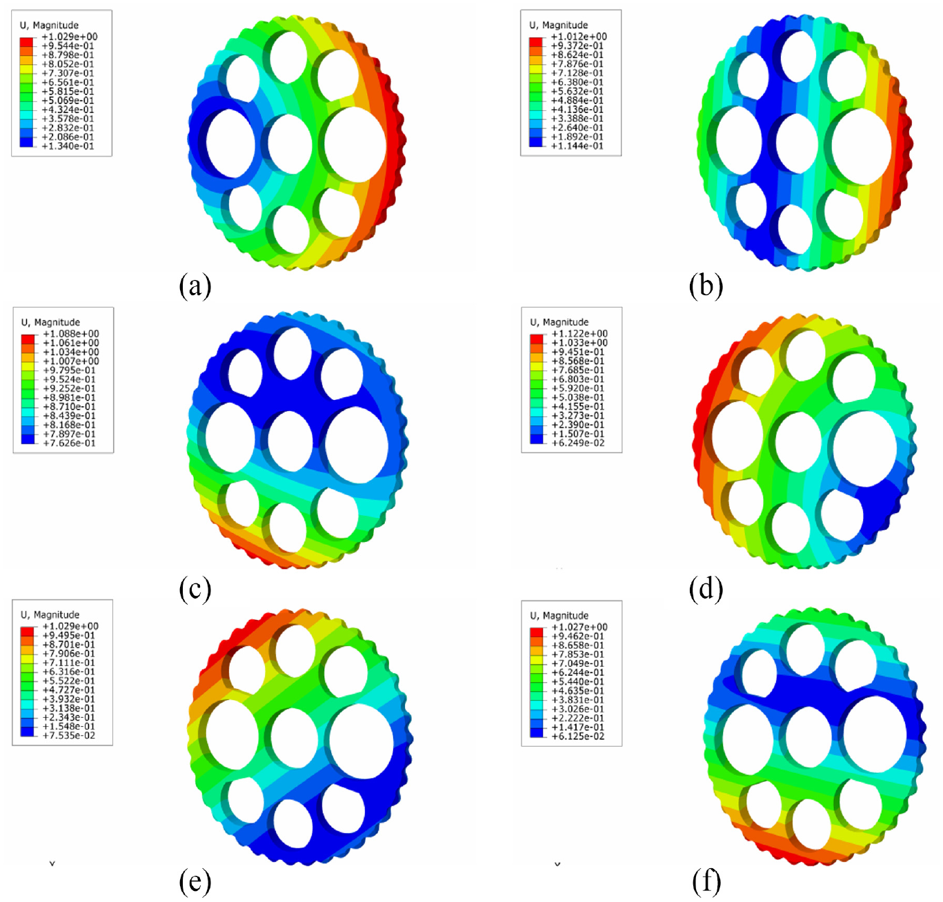
Vibration mode of the cycloidal gear: (a) first-order mode, (b) second-order mode, (c) third-order mode, (d) fourth-order mode, (e) fifth-order mode, and (f) sixth-order mode.
Vibration mode description of cycloidal gear.

As observed from the vibration mode pattern of the cycloidal gear, the natural frequencies of the first three order modes were all zero, all of which were rigid bodies; therefore, they were not considered in the analysis process from the fourth-order to the analysis of the natural frequencies and vibration modes. From the fourth to the sixth order modes, the natural frequency was very small, the position of the maximum vibration amplitude was at the 1/4 edge of the cycloidal gear, the vibration modes all exhibited a slight swing in the XY plane, and the dynamic performance of the entire cycloidal gear was better. In the seventh order mode, the natural frequency of the cycloidal gear increased to 1991.5 Hz, and the deformation begins to appear; the modal vibration mode of the cycloidal gear was primarily a two-way spiral twist, and the stress concentration was distributed evenly on the four edge meshing teeth. The eighth-order natural frequency of the cycloidal gear was 2142.1 Hz, the maximum stress was distributed evenly on the four edge meshing teeth, and the main vibration mode was the expansion bending from the vertical direction to the inside and outside. The natural frequency of cycloidal gear under the ninth order vibration mode was 3170.3 Hz, and the maximum vibration amplitude was concentrated on the center; the main vibration mode was the outward expansion and bending in the Z direction. In the final tenth-order vibration mode pattern, the vibration mode was primarily manifested by the irregular bending deformation on the front of the entire cycloidal gear, and the natural frequency of the vibration mode was 4824 Hz.
The maximum stress of the cycloidal gear was primarily concentrated on the edge of the meshing tooth surface, and the pressure angle gradually decreased as the stress value increased. As the cycloidal gear and crankshaft were fixed, the eccentric motion of the crankshaft caused the cycloidal gear to produce a centripetal force when it meshed with the pin gear and they squeezed each other to form an impact stress, resulting in vibration deformation. Therefore, the cycloidal gear can be modified to improve its stiffness and quality, change the force condition, and reduce mesh vibration and noise.
Modal analysis of the RV reducer
The 3D entity assembly model was saved in SolidWorks as a *.x_t intermediate file format and imported into ABAQUS through the Import Part function. After setting the analysis type, the free grid of the RV reducer was divided into 94,052 units and 178,452 nodes, and the grid finite element model of the entire system is shown in Figure 4.

Assembly diagram of the RV reducer.
The iterative algorithm was used to extract the first 10 natural frequencies of the RV reducer and the corresponding mode of the vibration pattern. Depicted in Figure 5, the description of the modes of the entire system is presented in Table 5.

Vibration mode of the RV reducer: (a) first-order mode, (b) second-order mode, (c) third-order mode, (d) fourth-order mode, (e) fifth-order mode, and (f) sixth-order mode.
Vibration mode description of the RV reducer.

The following conclusions were obtained by observing and analyzing the overall modes of the RV reducer: the natural frequency of the RV reducer was 345.73 Hz in the first-order model of the system, its modal shape was primarily expressed as the left and right wings of the planetary frame in the XY plane, and the larger amplitude of the vibration was on the edge of the planetary frame and pin gear housing. The natural frequency of the second-order model was 352.05 Hz, the main modal shape was the slight swing of the pin gear housing in the XY plane, and the stress was concentrated on the entire outer circle of the pin gear housing. In the third-order vibration pattern, the pinion shell and planetary carrier oscillated in the Z direction, and the natural frequency was 352.43 Hz, which was close to the second-order frequency. In the fourth vibration pattern, the modal vibration modes were primarily manifested in the torsion of the pin gear housing and cycloidal gear around the axis, and the stress concentrated on the lower edge of the pin gear housing, with a natural frequency of 1542.8 Hz, and the vibration amplitude of the third order increased. The overall fifth-order modal natural frequency was 1959.1 Hz, and the main mode shapes were similar to those of the third order; only the maximum stress moved along the forward direction in the Z axis. The natural frequency of the sixth order mode was 2101.7 Hz, which was the same as that of the fourth-order mode, all of which were the twists of the pin gear housing and cycloidal gear around the Z axis. The amplitude of the vibration tended to move from the pin gear housing in the Z direction. The seventh and eighth orders were all stable. The main mode was the oscillation of the planetary wheel in the XY plane, and the maximum stress values of the meshing edge of the planetary gear were the same. The natural frequencies of the two orders were very similar, 2948.3 and 2985.9 Hz respectively. The ninth and tenth order forms of the main components bend around the Z axis, the natural frequencies were 3610.2 and 3703.8 Hz, and the maximum stress was still at the meshing edge of the planetary gear.
This vibration mode analysis of the RV reducer indicated that the maximum displacement in the XY plane was primarily at the outer edge. In addition, the maximum stress was concentrated here, primarily because the mesh stiffness was excessively small and prone to straining. The planetary gear had a large swing in the seventh to tenth modes, resulting in an apparent displacement. The cycloidal wheel was also bent in the fourth- and sixth-order modes, possibly because they were close to their natural frequencies relative to the other components. By changing the quality and density of the pin gear housing, planetary frame, planetary gear, and cycloidal gear, the design parameters were optimized to improve the stiffness and reduce the bending stress to further improve the vibration characteristics of the reducer. The cloud chart that the vibration displacements of the other components were small. Combined with the static characteristics, the reducer satisfied the design requirements and the structure was reasonable. According to the formula of gear meshing frequency, the rotation frequency of the RV reducer was obtained as
Data analysis of vibration and modal testing
Vibration test and data analysis
A variable frequency speed control motor was used as the driving force of the test input source, and the speed of the input terminal was adjusted using a variable frequency controller. A torque sensor was used to measure the output torque of the reducer, and the change in speed and torque of the reducer was monitored in real time using a torque tester. A load was applied to the reducer using a magnetic powder brake. The size of the load was changed by adjusting the current in the controller of the magnetic powder brake. Finally, the vibration signal was using an M+P tester, and the signal data were processed using computer software. According to the measured data, we designed and built the vibration signal test physical platform and its structure, as shown in Figures 6 and 7.

RV reducer test platform.

RV reducer test bench diagram and test principle.
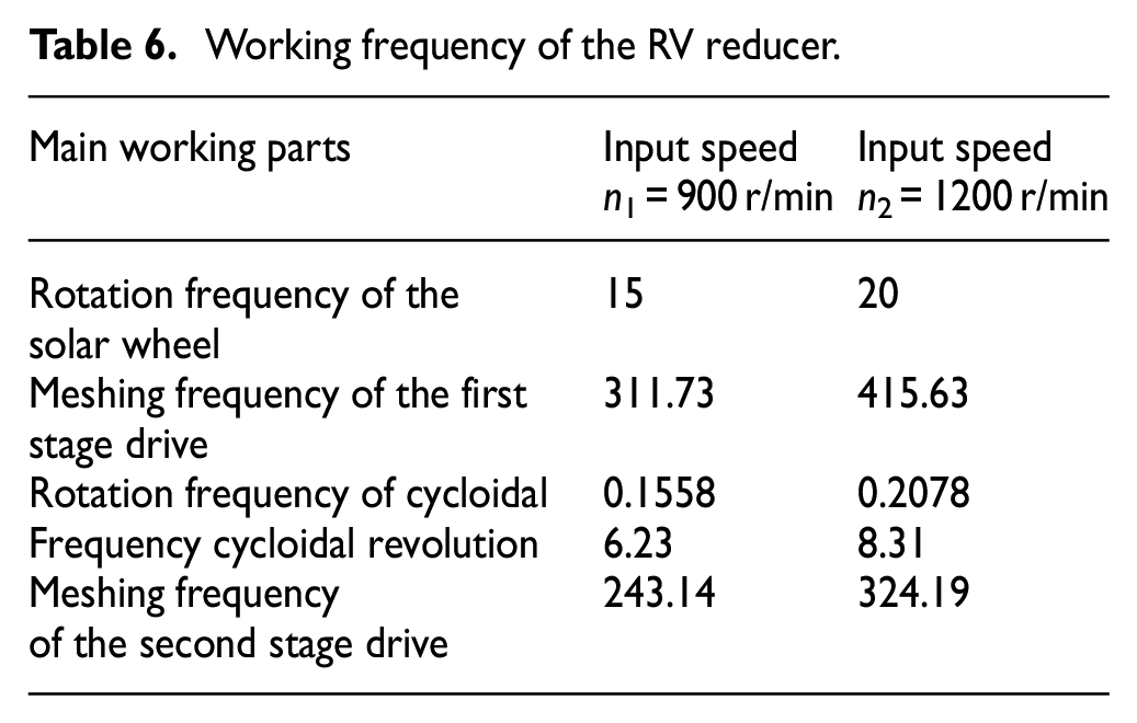
As the vibration characteristics of the RV reducer are closely related to the working frequencies of its working parts, it is necessary to calculate the working frequencies of the main working parts, compare them with the vibration data images collected in the experiment, and determine the main factors affecting the vibration characteristics of the RV. The vibration signals were analyzed in the time and frequency domains under the three working conditions. Under the first working condition, the speed was 900 r/min, and the load was 100 Nm. Under the second condition, the speed was 1200 r/min, and the load was 100 Nm. Under the third condition, the speed was 1200 r/min, and the load was 150 Nm. The installation mode of the RV reducer was fixed in a pin-tooth housing. The working frequencies of the main working parts under input speed of 900 and 1200 r/min are shown in Table 6.
Working frequency of the RV reducer.
In the vibration test of the RV reducer, the three working conditions were set up and tested on a test bench. The frequency-domain signals of the RV reducer under different working conditions were collected, and the vibration spectra are shown in Figures 8 to 10, respectively.

Vibration spectrum in the first working condition.

Vibration spectrum in the second working condition.

Vibration spectrum in the third working condition.
To facilitate a comparative analysis, we marked and numbered the vibration acceleration amplitude in the characteristic spectrum of the reducer. The calculation showed that the rotational frequency of the spindle was approximately 15 Hz when the middle speed was 900 r/min and 20 Hz when the second speed was 900 r/min. In the vibration spectrum of working condition 1, apparent peaks were observed at the locations of reducer labeled B1, B2, and B3. The peaks of vibration acceleration at the three locations were 0.0112, 0.0109, and 0.0105g, respectively. The corresponding frequencies of the three peaks were 16, 17, and 16 Hz, respectively, which were close to the rotational frequencies. This indicated that the generation of these amplitudes is related to the rotational frequencies of the input shaft. Moreover, there were apparent peaks of vibration acceleration at positions A1, A2, and A3, which were 0.0216, 0.0213, and 0.021g, respectively. The corresponding frequencies of these three peaks were 0.145, 0.15, and 0.16 Hz, which were very close to the cycloidal wheel’s rotation frequency of 0.1558 Hz under this working condition; therefore, the cycloidal wheel’s rotation is an important factor affecting the vibration characteristics of the RV reducer. Because there is an initial meshing clearance when the cycloidal gear meshes with the pin teeth, owing to the existence of cycloidal gear modification, the actual meshing teeth will be less than half of the theoretical meshing teeth. Additionally, the initial meshing clearance between the cycloidal gear and pin teeth increases correspondingly through the modification of the cycloidal gear. Thus, the collision excitation force is generated when meshing contact between the teeth of the cycloidal and pin teeth occurs, and a periodic excitation force is generated by the continuous meshing transmission between the cycloidal and pin teeth.
In cases 2 and 3, the amplitudes of the vibration acceleration in the X, Y, and Z directions all appeared to peak near the rotational frequency of the input shaft at 20 Hz, which may be due to the approximation between the rotational frequency of the input shaft and the natural frequency of some components. Similarly, in cases 2 and 3, the vibration acceleration amplitudes in the X, Y, and Z directions also exhibited peak values near the meshing frequency of the cycloidal gear of 0.2078 Hz. Additionally, the amplitude of the vibration acceleration at position B4 in condition 2 was 0.021g, which was larger than that at position B1 of 1.0112g. The amplitude of the vibration acceleration at the position of label C4 in condition 2 was 0.0851g, which was also larger than that at C1 in condition 1. This indicated that an increase in the input speed increased the amplitude of the vibration. In the same direction, the amplitudes of the vibration acceleration at B7 in condition 3 and B4 in condition 2 were 0.015 and 0.021g, respectively. In the same direction, the amplitudes of the vibration acceleration at C7 in condition 3 and C4 in condition 2 were 0.0793 and 0.0851g, respectively. In the two sets of data, the amplitude of the vibration response corresponding to the two frequencies in working condition 3 was lower than that in working condition 2, which indicated that the increase in torque load decreased the amplitude of vibration. In conclusion, the analysis confirmed that the rotational speed of the input shaft influences the vibration characteristics of the RV reducer. Under a certain load, the response amplitude of the vibration acceleration increased with an increase in the rotational speed of the input shaft, and under the same rotational speed, the response amplitude of the vibration acceleration decreases with an increase in the load of the input shaft. The peak values of E1 and E2 were 350 and 350.2 Hz, respectively, which were close to the second natural frequency of the reducer, and their amplitudes were 0.0225 and 0.0221g, respectively. Therefore, resonance occurred near the second natural frequency, which resulted in a slight impact vibration. The same phenomenon was observed under the other two working conditions. Combining all the spectrograms, we observed that even if the speed of the input shaft increased, no resonance occurred. The small peaks in some frequency stages were mostly the micro-vibrations of internal parts owing to assembly errors or impact in the transmission process, and these amplitudes were not high. This showed that the overall dynamic performance of the RV reducer was good.
We observed the spectrum of the three working conditions, the peak value of the vibration acceleration appears near the first and second meshing frequencies. In the first working condition, the amplitudes of the vibration acceleration corresponding to the X, Y, and Z directions near the first meshing frequency 311.73 Hz were 0.019, 0.0188, and 0.019g, respectively. The second meshing frequency was 243.14 Hz in the X, Y, and Z directions. The amplitudes of the vibration acceleration corresponding to the second meshing frequency were 0.0758, 0.0753, and 0.0749g, respectively. The amplitudes of the vibration acceleration corresponding to the second meshing frequency were larger than those corresponding to the first meshing frequency. Because the transmission of the RV reducer was relatively large, the excitation force generated by the meshing impact of the first-stage spur cylindrical solar wheel and planetary wheel could only act on the output parts and shell through the transmission of the second-stage transmission mechanism with a large transmission ratio. Therefore, the second-stage transmission mechanism effectively weakened the exciting force produced by the first-stage meshing, and the cycloidal wheel motion state was transmitted to the output components through equal-ratio transmission. Thus, the exciting force generated by the meshing impact of the cycloidal gear and pin teeth also directly acted on the output components and shell. Therefore, the impact of the second cycloidal pin gear meshing on the vibration characteristics of the RV reducer was greater than that of the first straight cylindrical solar wheel and planetary wheel meshing. Under these three conditions, the amplitude of the vibration acceleration corresponding to the second meshing frequency in the same direction was also significantly larger than that corresponding to the vibration acceleration of other frequency components. This showed that the meshing impact of the cycloidal pin gear has the greatest impact on the vibration scenario. Because the contact force between the cycloidal wheel and needle wheel is very close to the modification of the cycloidal wheel, it is necessary to optimize the modification of the cycloidal gear.
Modal experiments and data analysis
Since the entire machine is composed of multiple parts that interact with each other and are affected by various factors such as lubrication conditions, assembly conditions, and vibration transmission, it is necessary to conduct sufficient experiments to obtain stable and relatively accurate results.
Based on the modal analysis results of finite element theory, the experimental testing scheme is divided into four tests. Each test is stimulated in the axial direction and circumferential direction of the needle bearing cage and the sun gear. Ten measuring points are set up in the axial direction of the needle bearing cage, arranged in a regular hexagonal pattern. The measuring point layout of the RV reducer is shown in the Figure 11.
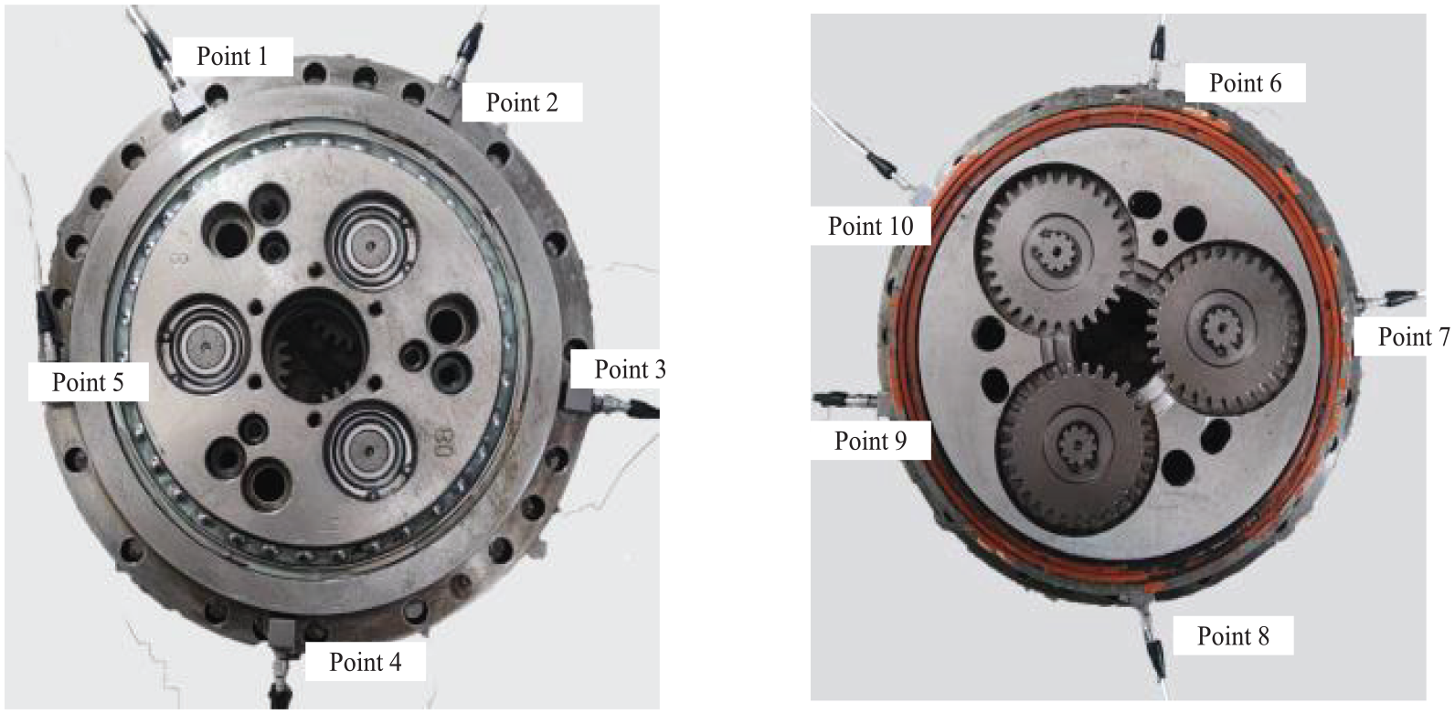
Measuring point layout of the whole machine.
Based on complex mode single-degree-of-freedom analysis and taking into account factors such as avoiding modal nodes and excitation positions, four tests were conducted at peripheral measuring points 1, 4, 7, and 10, and the overall frequency of the RV reducer was obtained as shown in Table 7.
RV reducer natural frequency.

Next, test the natural frequency of the main component cycloid wheel in the RV reducer. In order to ensure the accuracy of the natural frequency and uniquely and completely describe each modal vibration mode, the cycloid wheel is arranged with six measuring points in a regular hexagon in its axial direction and only one axial excitation is performed. The layout of the measuring points on the cycloid wheel is shown in the Figure 12.
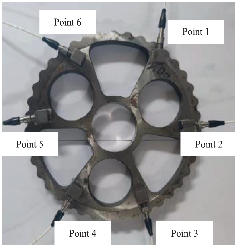
Measuring point layout of the cycloid wheel.
By testing the natural frequency of the cycloid wheel, the actual natural frequency of the cycloid wheel is shown in the Figure 13. The first to third natural frequencies are 1531.25, 2312.5, and 5187.5, respectively.
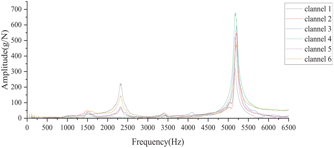
Measured natural frequency chart of the cycloid wheel.
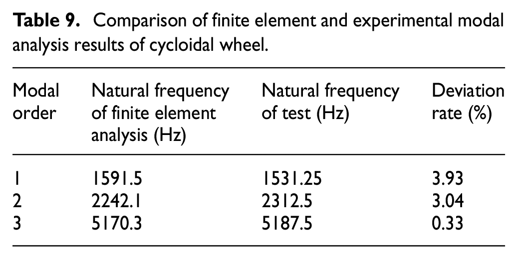
By comparing the measured and theoretically fitted frequency response function curves, it can be found that although there is a peak shift phenomenon in some high-frequency intervals, in the low-frequency interval, the measured frequency response function curve has a good degree of conformity and high fitting accuracy. The simulation data are collated and summarized, and the experimental modal data are compared with the simulation data above to obtain the comparison table shown in Tables 8 and 9. The results show that the error is less than 9%, and the natural frequency correlation is good, which verifies the correctness of the above simulation.
Comparison of finite element and experimental modal analysis results of the RV reducer.

Comparison of finite element and experimental modal analysis results of cycloidal wheel.
Conclusion
Based on theoretical analysis and experimental tests, the vibration characteristics of the RV reducer were studied, and the main conclusions are as follows:
(1) The general transmission ratio formula of the RV reducer was calculated according to the structural characteristics and transmission principle of the RV reducer. The stress conditions of the cycloidal wheel, planetary wheel, and crankshaft were deduced and analyzed in detail using the conversion mechanism method. This lays a theoretical foundation for the industrial design of these key components and the dynamic performance test of the entire system.
(2) Three-dimensional parametric solid modeling for each part of the RV reducer was performed and simplified. The finite element analysis model was obtained in the free mesh in ABAQUS, and the first 10 natural frequencies and vibration modes of the RV reducer were extracted using modal analysis. The lowest first natural frequency was 345.73 Hz, which completely avoided the input rotational frequency calculated using the theory; thus, there was no resonance phenomenon in the state of normal operation, the dynamic performance was good, the structure was reasonable, and it satisfied the design requirements.
(3) Additionally, the modal analysis of the input shaft and cycloidal gear was performed, and their natural frequencies and vibration modes were obtained. The vibration patterns of the RV reducer, as well as the input shaft and cycloidal gear, were analyzed comprehensively. The weak part of the entire transmission system was observed to be the meshing of the pin gear housing, planetary gear, middle of the input shaft, and cycloidal gear. The stiffness of these positions is low, and the regularity of the vibration pattern is summarized, which provides guidance and optimization methods for the structural design and dynamic performance improvement of the RV reducer.
(4) The frequency domain response of the vibration signal under different working conditions was analyzed through a vibration characteristic test. When the vibration acceleration of the RV reducer in the X, Y, and Z directions approached the second meshing frequency, it reached the maximum peak value, which was the meshing frequency of the second cycloidal pinwheel. This indicates that the meshing impact will have the greatest impact on the vibration characteristics of the RV. In the X and Y directions, the vibration acceleration of the RV reducer also exhibited a peak value corresponding to the second natural mode frequency, which verified the accuracy and reliability of the modal analysis of the RV reducer.
Footnotes
Handling Editor: Chenhui Liang
Declaration of conflicting interests
The author(s) declared no potential conflicts of interest with respect to the research, authorship, and/or publication of this article.
Funding
The author(s) disclosed receipt of the following financial support for the research, authorship, and/or publication of this article: This work was supported in part by the National Natural Science Foundation of China Youth Fund under Grant 52005157, in part by the union fund of science and technology R&D plan of Henan Province (Grant No. 222103810040), in part by the Key scientific research projects of higher education institutions in Henan Province (Grant No. 23A460017).