
Abstract
In the factory, the steel round bar sawing machine is applied to finish the sawing mission. Due to the process of the sawing steel is operating in high speed, the grinding-wheel-saw (GWS) is quickly worn by the friction and replaced frequently. The automatic replacement system of GWSs is seldom built yet. To improve the efficiency of the replacement for GWSs, the machine-vision-based intelligent robotic replacement system (MIRRS) for GWSs is developed and reported in the study. The MIRRS is mainly consisted of the six degrees-of-freedom (DOF) manipulator and the six-axes mechanical arm system to successfully complete the task of the replacement. The finite element method (FEM) is applied to analyze and design the subsystem of the MIRRS. Besides, the machine-vision positioning system associated with the digital camera are also setup to provide the required feedback detections for the MIRRS. The hardware system architecture and the control flow chart are described in detail and the hundreds of realistic testing results are collected to verify the reliability and offer the well working efficiency of the designed MIRRS.
Keywords
Introduction
In the recent, the intelligent manufacturing technology was pointed out1–5 to motivate the steel industry has launched several initiatives to enhance the efficiency and the quality of production, and reduce the manual labor intensity. Besides, due to the related industry 4.0 development strategies have been promoted overall the world,6–9 the rise and application of automatic equipment were further introduced into the steel industry. The automation equipment for the grinding, cutting, and sawing of steel or casting parts has been greatly developed. For example, the machine-vision-based robotic polishing system for the rub of car wheel, 10 the robotic polishing high-bandwidth end-effector, 11 the intelligent monitoring system for the grinding wheel, 12 and the automatic deburring system of casting items 13 were reported.
The increase of the export has been required the higher quality of steel products, such as steel round bar and section steel. The end face of a steel product sawing by grinding-wheel-saw (GWS) has the smooth incision, no burr, and the well quality of production. Sawing machine with GWS has been paid more attention. The proportion of high-level steel products made by the saw machine with GWS is increasing gradually.
For the sawing of the steel round bar, when the machine is normally operating, the sawing speed of the GWS is continuously maintained a certain value for achieving the sawing task smoothly. Due to the process of the sawing steel is at the quite high speed, the GWS is quickly worn by the friction. It leads that the diameter of GWS is dynamical reduction rapidly. It is necessary to continuously accelerate the rotational speed of the spindle to reach a stable tangential speed for sawing. When the diameter of the GWS is gradually decreased to a certain value and the rotational speed of the spindle is reached to the critical highest value, the tangent speed on the tip of the GWS is not enough to support the smooth sawing process. It means that the replacement of the old and new GWSs is frequently required.
In current steel industry, it is not yet realized the replacement of GWSs for the steel round bar sawing machine by the automatic equipment. In general, the average time of manual operation to complete the replacement of GWSs is taken more than 2 h. Besides, there are many disadvantages in the process of the manual replacement for GWSs.
(1) The single GWS, which is 50 kg in weight and 1250 mm in diameter, is quite large for the operators. The manual replacement requires the application of the spreader, the large open wrench, and the other auxiliary tools. The total task of the replacement for GWSs is difficult and has a certain risk.6–9
(2) In the steel factory, the working environment is in high temperature, dust, vibrational noise, and other influencing factors. The safety of workers to operating the task of the replacement is not surely guaranteed. 14
(3) When the new GWS is installed, the pre-tightening torqued force of the hex nut to rivet the GWS is difficult to regulated. In the sawing process, the too larger or smaller tightening torques applied to the hex nut may be caused the adverse effects of the GWS and even leads to the GWS in bursting.
With the development of robotic technology, the series robot has become an important equipment to settle the grinding, cutting, and sawing processing problems in the steel industry. The series robot provides high flexibility for the practical application. Compared with the manual operation, the efficiency and the quality of productions by applying the robotic operation are obviously improved. The series robot is gradually and widely used in steel and casting cutting, grinding, polishing, spraying, and other tasks.15–17 Therefore, the adoption of the series robotic equipment instead of the manual operation to achieve the efficient replacement of GWSs has become an urgent requirement of the steel industry. The development of the key technologies for the series robotic equipment is the core to promote the rapid development of the sawing technology in the steel industry.
Motiving by the aforementioned analysis, the development of an intelligent robotic replacement system is arisen. In the literature, the intelligent replacement system of GWSs for the steel round bar machine is rarely reported. For the frequent requirements of replacing the smaller types of grinding wheels for the polishing equipment, the image-detected and the infrared-detection based wheel replacement systems were proposed, respectively.18,19 The automatic changing mechanism of grinding wheel for an electric grinding machine was provided in Wu. 20 In Ma, 21 the robotic mechanism for rapidly changing the small grinding wheel, which is fixed by a telescopic rod, was exposed. However, the automatic and intelligent replacement system of GWSs for steel round bar machine utilizing the machine-vision technology has seldom been setup yet.
The main contribution of this study is to report a machine-vision-based intelligent robotic replacement system of GWSs for solving the existing difficulties of the manual replacement of large GWS in the steel round bar machine. The remainder of the study is organized as follows. In Section “Overall structure and main modules,” the problem of the replacement for GWSs is described. The overall structure of the machine-vision-based intelligent robotic replacement system (MIRRS), which are mainly consisted of the 6DOF manipulator and the six-axes mechanical arm system, are introduced. The main modules contained in MIRRS are also provided in detail. The machine-vision positioning system, which is served for the MIRRS to compute the central axis and position of the spindle, is addressed in Section “Machine-vision positioning system.” The hardware system architecture, the control flow chart, and the realistic tests of the MIRRS are proposed and performed in Section “System architecture, control flow chart, and realistic test.” Finally, the concluding remarks are given.
Overall structure and main modules
The hardware device of grinding-wheel-saw (GWS) in the steel round bar sawing machine is shown in Figure 1. The GWS is inserted on the spindle and riveted with a hex nut and a flange, as shown in Figure 2. In order to realize the task of replacement for the GWS with the automatic equipment, the developed and designed equipment is responsible for solving the disassembly and installation of the hex nuts and the flange, as well as the problems of catching, removing, and transporting the old and new GWSs.

The steel round bar sawing machine.

The hex nut and the flange on the spindle.
To successfully complete the task of the replacement for the GWSs, the machine-vision-based intelligent robotic replacement system (MIRRS) for the steel round bar sawing machine is developed and reported in this study. In Figure 3, the MIRRS of GWS is mainly constituted by two parts.

Machine-vision-based intelligent robotic replacement system of GWS.
The first part is the six degrees-of-freedom (DOF) manipulator, which includes the unscrewing and tightening module (UTM) of the hex nut and the dismantled and assembly module (DAM) of the hex nut and the flange. The UTM is applied to unscrew and tighten the hex nut on the spindle. The DAM is to complete the disassembly and assembly of the hex nut and the flange on the spindle. The second part is the six-axes mechanical arm system, which contains the six-axes robot arm with the vacuum sucker adsorption module (VSAM) and a digital camera mounted on the end-effector. It is used for catching or removing and transporting the old and new GWSs. The machine-vision positioning system associated with the digital camera has been setup in the overall control system. The function blocks of the modules in the MIRRS are depicted in Figure 4.

Function blocks of the modules in the MIRRS.
The operated procedures of the MIRRS of GWS have five stages and summarized in the following.
Stage (1), to start the replacement, the center position of the hex nut on the spindle is detected by the digital camera. The certain positioning results are performed by the machine-vision positioning system and feedforward to the motion control system.
Stage (2), the six DOF manipulator is moved to disassemble and extract the hex nut and the flange. Firstly, the UTM is moved to align with the central axis of the spindle and, then the hex nut is unscrewed. Second, the DAM is moved to align with the central axis of the spindle to finish the extractions of the hex nut and the flange in the sequel.
Stage (3), the six-axes mechanical arm system is operated to absorb the old GWS and deliver it to the storage place of the discarded GWSs.
Stage (4), the machine-vision positioning system is operated again to locate the storage place of the new GWSs. The new GWS is taken and transported by the six-axes mechanical arm system to insert on the spindle.
Stage (5), the six DOF manipulator is started again to install the flange and the hex nut on the spindle by the DAM in sequence. Finally, the hex nut is tightened by the UTM.
Six DOF manipulator for the hex nut and the flange
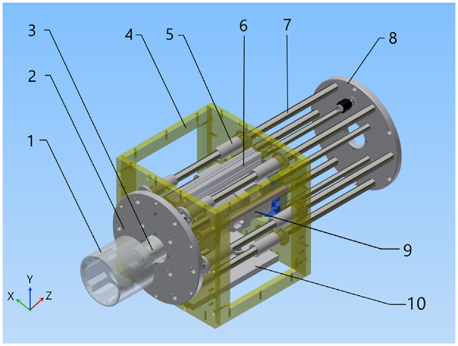
The schematic diagram of the six DOF manipulator is shown in Figure 5. The coordinates frame is also depicted. The overall size of the manipulator is 3760 mm × 2485 mm × 1130 mm. It comprises the UTM (2) for the hex nut and the DAM (1) for the hex nut and the flange. Both of the UTM (2) and the DAM (1) are mounted in the same frame to form the disassembly and assembly execution unit (DAEU). The horizontal servo motor driven device (3) and the vertical servo motor driven device (4) are also installed such that the DAEU is enabled to move in the horizontal (X axis) and vertical (Y axis) directions. The six DOF manipulator has six DOFs, among which three DOFs are driven by three servo motors, two DOFs are driven by two linear pneumatic cylinders, and the other one is used for the movement of the pneumatic wrench.

Schematic diagram of the 6DOF manipulator.
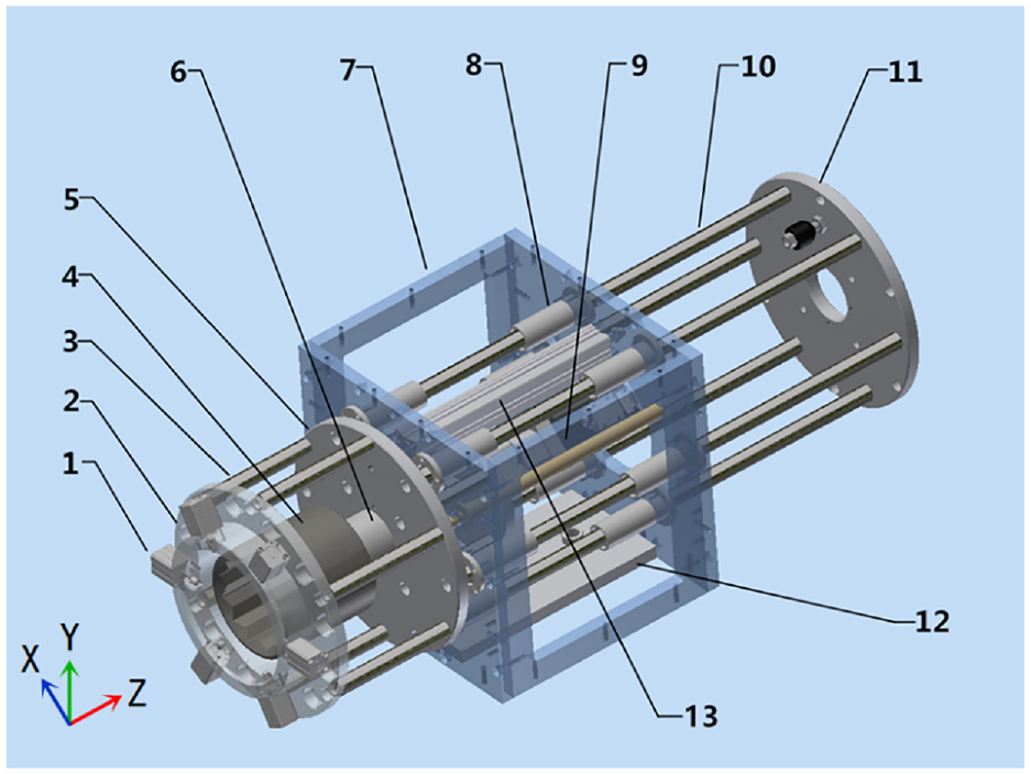
Considering the coordination of motion and the operational efficiency of the DAEU, the design of the DAEU is to arrange the UTM (2) and DAM (1) adjacent to each other in the same frame. The hardware entity is shown in Figure 6. The size of the DAEU is 1180 mm × 400 mm × 800 mm.

The hardware entity of the DAEU.
When the GWS is operating in the sawing mission, the spindle is in the state of high-speed rotational motion to realize the sawing action. However, when the steel round bar sawing machine is to stop, the spindle cannot accurately return to the initial starting position. It induces that the six DOF manipulator is required the ability to adjust the position such that both of the UTM (2) and the DAM (1) can align with the central axis of the spindle. The motions of the six DOF manipulator are summarized in the following.
Motion 1. Translational motion in the X-axis direction: The DAEU is installed in the vertical lifting frame. By operating the horizontal servo motor driven device (3), the vertical lifting frame contained the DAEU is moved in the X-axis direction in front of the spindle and the GWS.
Motion 2. Translational motion in Y-axis direction: The vertical movement of the DAEU in the vertical lifting frame is accomplished by operating the vertical servo motor driven device (4). By adjusting the position of the vertical lifting frame in the X-Y plane, the DAEU is controlled to align with the central axis of the spindle.
Motion 3. The freedom of translation in the direction of Z axis: The DAEU is driven by two linear pneumatic cylinders to make sure that the UTM (2) and the DAM (1) are moved in the center-axial direction of the spindle.
Motion 4. Two degree-of-freedoms of rotational motion: They realize the unscrewing and tightening of the hex nut and the dismantled and assembly actions of the hex nut and the flange. The hex nut is unscrewed and tightened by a pneumatic wrench. The removal of the hex nut on the spindle is finished by the controlled servo motor with the driven rotational motion.
Unscrewing and tightening module (UTM)
The hex nut (M80) on the spindle is unscrewed and tightened by the sleeve linked to the pneumatic wrench. The sleeve has to be aligned with the central axis of the spindle to achieve contact and separation. The required center position of the spindle is identified by the machine-vision positioning system, which is reported in the Section “Machine-vision positioning system,” to realize the center-axial alignment. Due to the inertia of GWS, the flange, and the hex nut on the spindle, the pneumatic wrench with the sleeve can unscrew and tighten the hex nut by the rapid impulse of pneumatic impact under the free rotational motion of the spindle.
The schematic diagram of the UTM is shown in Figure 7. The module is consisted of a translational frame and a rotational frame. The output shaft of the pneumatic wrench (9) is connected with the 12-angle sleeve (1) through the elastic coupling (3) to form a rotational frame. It ensures that the 12-angle sleeve (1) and the hex nut are contacted and separated smoothly. Besides, the output torque of the pneumatic wrench is smoothly transferred to the sleeve.
Schematic diagram of the unscrewing and tightening module (UTM).
The frame, which is composed of the bearing frame (4), the connected rods (7), the front flange (2), and the rear flange (8), retains an enough space in the middle. It is equipped with the pneumatic wrench (9) to form a translational frame. The translational frame, which is connected with the bearing frame (4) through the linear bearings (5), is placed on the bottom plate (10) can slide in the direction of the connected rods (7) forwardly and backwardly. The translational frame and the linear pneumatic cylinder (6) with position sensors are formed the telescopic device. It is moved to close to and away from the hex nut in the central axis of the spindle by controlling the linear pneumatic cylinder (6). The hex nut can be put into the 12-angle sleeve.
The aforementioned UTM can operate the translational movement in the center-axial direction of the hex nut to complete the contact and separation between the 12-angle sleeve (1) and the hex nut. Meanwhile, it can rapidly unscrew and tighten the hex nut by the pneumatic wrench with the high-pressure pneumatic source. The detailed procedures of action for the UTM are summarized in the following.
(I) Procedures of unscrewing the hex nut.
Step 1. By means of the center-positional information of the spindle, which is identified by the machine-vision positioning system, the UTM is driven such that the 12-angle sleeve (1) is aligned with the central axis of the hex nut on the spindle.
Step 2. The rotational frame is translationally moved by operating the linear pneumatic cylinder (6) such that the hex nut is put into the 12-angle sleeve (1).
Step 3. The pneumatic wrench (9) is started up in the counterclockwise rotation to complete the unscrewed task of the hex nut by the driven 12-angle sleeve (1).
Step 4. The rotational frame is translated away from the hex nut to the initial position in the UTM to complete the separation between the 12-angle sleeve (1) and the hex nut. The enough working space is left for the subsequent disassembly of the hex nut, the flange, and the old GWS.
(II) Procedures of tightening the hex nut.
Step 1. When the new GWS, and the flange, and the hex nut are inserted on the spindle in sequence, the UTM is driven again such that the 12-angle sleeve (1) is aligned with the central axis of the hex nut on the spindle.
Step 2. The rotational frame is translated again by operating the linear pneumatic cylinder (6) such that the hex nut is put into the 12-angle sleeve (1).
Step 3. The pneumatic wrench (9) is started up in the clockwise rotation to complete the tightened task of the hex nut by the driven 12-angle sleeve (1).
Step 4. The rotational frame is translated away from the hex nut to the initial position in the UTM. Finally, the UTM is reset.
Torque control of the pneumatic wrench
When the new GWS is installed on the spindle, the required tightening torque of the hex nut is up to 2000 N m. During the sawing process, applying the too larger or smaller tightening torque to the hex nut causes the adverse effects of the GWS and even leads to the GWS in bursting. To provide the regulated tightening torque, the feedback control system is built by adding the torque sensor with the data signal transducer in the hardware of the pneumatic wrench. The block diagram of the regulated torque feedback control system for the pneumatic wrench is shown in Figure 8. The required tightening torque is performed by suitable tuning the reference torque command.

Block diagram of the regulated torque feedback control system.
Dismantled and assembly module (DAM)
When unscrewing the hex nut on the spindle, the next task is to remove the hex nut and the flange at the end of the spindle. Then, the replacement of GWSs is operated in sequence. In addition, the flange and the hex nut need to be installed on the spindle after the replacement of the old and new GWSs is completed. Based on the requirements, the dismantled and assembly module (DAM) for the hex nut and the flange is designed. The schematic diagram of the DAM is shown in Figure 9.
Schematic diagram of the dismantled and assembly module (DAM).
The module is composed of two components. The first component is a moving frame that translates forwardly and backwardly in the direction along the long-connected rods (10). In the first component, the latch cylinder bracket (2) and the front flange (5) are fixedly connected by the short-connected rods (3). The six pneumatic latch cylinders (1) are mounted on the latch cylinder bracket (2). The front flange (5) and the rear flange (11) are fixedly connected by the long-connected rods (10) to form the base of the moving frame. It is connected to the bearing frame (7) through the linear bearings (8). The servo motor (9), which is linked to the 12-angle sleeve (4) through the elastic coupling (6), is carried on the connected plate (12), which is mounted on the base of the moving frame. The 12-angle sleeve (4) is installed between the space of the latch cylinder bracket (2) and the front flange (5) and the servo motor (9) is initially placed in the bearing frame (7).
The second component is a fixed frame, which is consisted of the bearing frame (7) and a linear pneumatic cylinder (13) with position sensors. The linear pneumatic cylinder (13) is mounted on the bearing frame (7) and linked to the front flange (5). The moving frame is driven by the linear pneumatic cylinder (13) to slide backwardly and forwardly in the direction along the long-connected rods (10).
To grasp the flange, the pneumatic latch cylinders are mounted on the latch cylinder bracket in the front of the DAM. Besides, the circular groove is made on the flange, as shown in the Figure 10. When the unscrewed and relaxed hex nut is put into the 12-angle sleeve (4), the hex nut can be screwed out or screwed in the spindle by driving the servo motor (9) connected through the 12-angle sleeve (4). Due to the outside of 12-angle sleeve (4) are equipped around the high magnetic permanent magnets, the screwed-out hex nut is kept in the 12-angle sleeve (4) by the permanent magnets.

Pneumatic latch cylinders and the circular groove of the flange.
The cylinder bracket (2) is equipped with six pneumatic latch cylinders (1). Each cylinder (1) with position sensors is attached to the latch (14), which is extended or retracted by driving the pneumatic control. The flange is grasped by extending the six latches (14) into the circular groove of the flange (15). On the contrary, the flange is released by retracting the six latches (14).
The procedures for dismantling and assembling the hex nut and the flange are summarized in the following.
(I) Procedure of dismantling the hex nut and the flange.
Step 1. According to the central-position information of the spindle, which is identified by the machine-vision positioning system, the DAM is moved to align with the central axis of the hex nut on the spindle.
Step 2. Driven by the linear pneumatic cylinder, the moving frame is translated toward the hex nut and the flange such that the hex nut is contained in the 12-angle sleeve and the flange is located into the front end of the DAM under the status of the retracts of the six latches.
Step 3. The six latches are expended into the circular groove of the flange by driving the pneumatic latch cylinders such that the flange is grasped.
Step 4. The 12-angle sleeve is driven by the servo motor to rotate the hex nut in counterclockwise rotation such that the hex nut is screwed out and separated from the spindle, and magnetically adsorbed in the 12-angle sleeve.
Step 5. The moving frame backwardly translates to the initial position in the DAM by carrying the hex nut and the flange. To this stage, the task of the dismantling the hex nut and the flange is complete.
(II) Procedure of assembling the flange and the hex nut.
Step 1. After the new GWS is installed through the spindle, the DAM, which carries the hex nut and the flange, is moved to align with the central axis of the spindle by means of the detected center-axial position from the machine-vision positioning system.
Step 2. The moving frame in the DAM, which carries the hex nut and the flange, is driven to translate toward the GWS such that the flange and the hex nut are inserted on the spindle in sequence.
Step 3. The 12-angle sleeve driven by the servo motor is started up to rotate the hex nut in clockwise rotation such that the hex nut is screwed in the spindle.
Step 4. The six latches are retracted from the circular groove of the flange by driving the pneumatic latch cylinders such that the flange is released. To this stage, the task of the assembling the hex nut and the flange is complete.
Step 5. The moving frame returns to the initial position in the DAM. Then, the DAM is reset.
Six-axes mechanical arm system
When the disassembly of the hex nut and the flange is finished by the aforementioned six-DOF manipulator, the task of the replacement for the old and new GWSs are operated in the sequel. According to the available working space in the factory site (4*1.15 m2 in area and 2.3 m in high) and the weight and the size of the GWS, the designed six-axes mechanical arm system, which contains the vacuum suckers for disassembling, assembling, and transporting the GWSs, is reported in the study. The schematic diagram is shown in Figure 11.

Schematic diagram of six-axes mechanical arm system.
The designed six-axes mechanical arm system is mainly consisted of a six-axes robot arm (3) and a vacuum sucker adsorption module (VSAM) (2), which is mounted on the end of the robot arm (3). The path of motion for the GWS is online planned by the control box (5) according to the information provided by the machine-vision positioning system. By controlling the VSAM (2) with the pneumatic pressure from the compressor (4) to implement the absorption or release of the GWS (1), the old and new GWSs are realized the capture, the transport, and the installation in the working space.
Six-axes robot arm
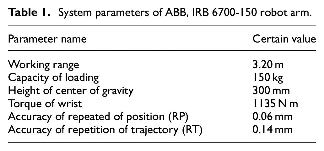
In this study, the ABB, IRB 6700-150 six-axes robot arm, which includes six DOF of the rotational motion, the end can move flexibly, and each joint can avoid obstacles, was selected to build the six-axes mechanical arm system. The hardware entity is shown in Figure 12. The system parameters and the performance are listed in Tables 1 and 2, respectively. 22

The hardware entity of the ABB, IRB 6700-150 robot arm.
System parameters of ABB, IRB 6700-150 robot arm.
Performance of ABB, IRB 6700-150 robot system.

Vacuum sucker adsorption module (VSAM)
To realize the disassembly, assembly, and transportation of the GWSs, the vacuum sucker adsorption module (VSAM) is designed and installed on the end of the six-axes robot system. The schematic diagram of the VSAM is shown in Figure 13.
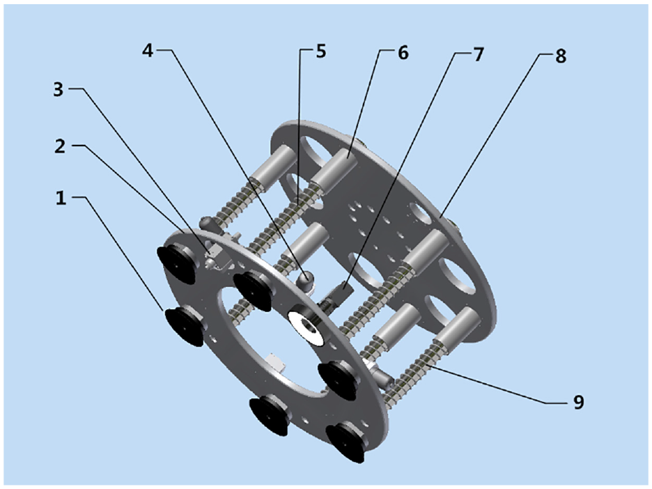
Schematic diagram of vacuum sucker adsorption module (VSAM).
The front flange (2) and the rear flange (8) are connected by the buffer springs (5), the connected rods (9), and the linear bearings (6) to form the based frame. The rear flange (8) is mounted on the end of the six-axes robot system. Six silicone-rubber vacuum suckers (1) are evenly distributed on the front flange (2) in a circular manner, and each vacuum sucker (1) is connected with the vacuum generator (4) and the pressure sensor, which is to detect the absorption of the GWS is completed. The digital camera (7) and the contact sensor (3) are also installed on the front flange (2) to capture the image of the hex nut for the detection of the center-axial position and to determine whether the GWS is in the front of the VSAM, respectively.
When the VSAM is ready to absorb the GWS, the contact signal is sensed by the contact sensor (3) to feedback to the control system. Then, the six vacuum suckers generate negative pressure by controlling the six vacuum generators to achieve the adsorption of the GWS. Each vacuum sucker has a diameter of 120 mm. The capacity of adsorption weight for one vacuum sucker is 36.0 kg in the status of the GWS in the horizontal attitude and it is 18.0 kg in the status of the GWS in the vertical attitude. Under the normal working pneumatic pressure source, the total adsorption force provided by the six vacuum suckers can performed the sufficient capacity of adsorption for the GWS in the horizontal or vertical transportation.
Analysis of placed locations of vacuum suckers by FEM
Considering the practical manufacturing procedure of the VSAM, the six vacuum suckers are located in the uniformly circular arrangement on the front flange. The diameter of the arranged circle is estimated by the finite element method (FEM) for the sufficient capacity of adsorption. The FEM is a common tool for analyzing the properties of mechanics for a mechanical structure, such as stress, strain, and displacement. 23 Many computational software packages have been developed for the FEM applications, such as CREO, ANSYS, and NASTRAN.24,25 Among of them, ANSYS shows the well calculation performance in analyzing various physical problems.26,27
The mesh of the prototype 3D model of the VSAM with a GWS is generated by reading the designed CAD file to the ANSYS software. The meshing results with 605,831 node numbers and 93,751 elements are illustrated in Figure 14.
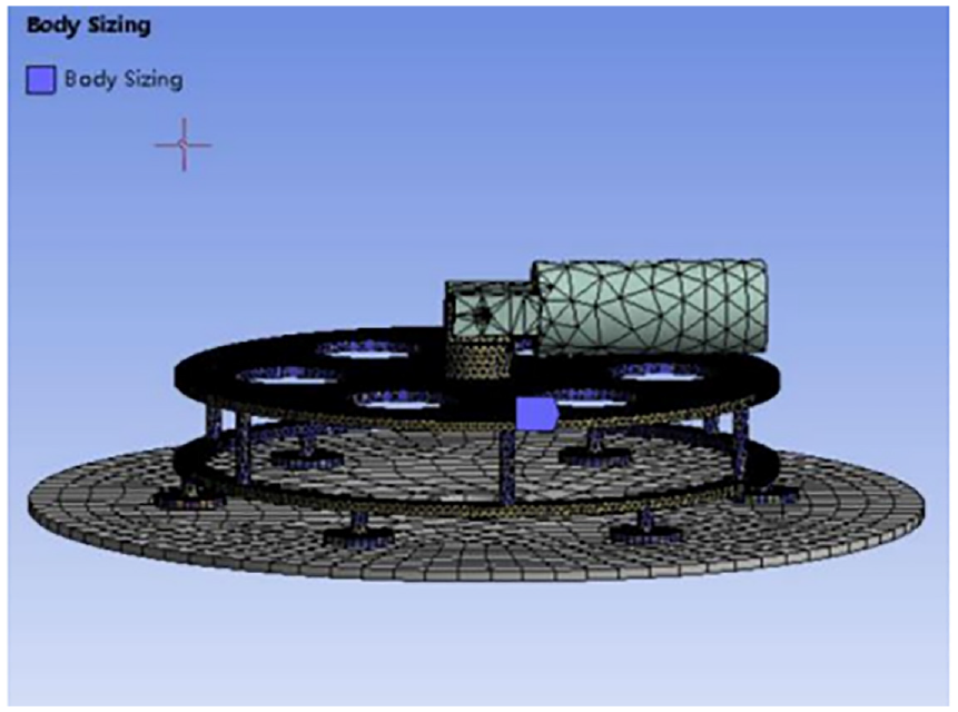
Meshing results of the VSAM.
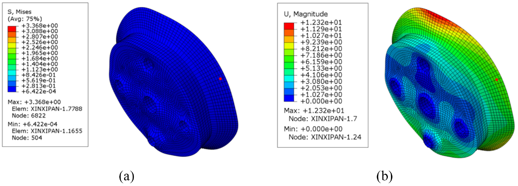
Due to the slow movement is operated during the transporting process of the GWS, the finite element simulations are basically considered by the gravitational field acting on the VSAM. It is shown in Figure 15. The structure material is selected by an aluminum alloy. Through the computations of the FEM software, the distributions of the von Mises stress and displacement for the VSAM with three different values of diameter, that is, 380, 805, and 980 mm, are depicted in Figures 16 to 18, respectively.

Actions of the gravity on the VSAM.

(a) Distributions of the von Mises stress with 380 mm (diameter) and (b) distributions of the displacement with 380 mm (diameter).

(a) Distributions of the von Mises stress with 805 mm (diameter) and (b) distributions of the displacement with 805 mm (diameter).
(a) Distributions of the von Mises stress with 980 mm (diameter) and (b) distributions of the displacement with 980 mm (diameter).
Discussions
1. Based on the simulating results by the FEM for three cases of the diameter of arranged circle, the small stresses and displacements are distributed in the ring region from the outer radius of the central hole to the inner radius of the GWS. The ring region is the wide range.
2. The suitable locations of the six vacuum suckers are determined analytically. Firstly, the ring region is uniformly divided to six pieces of region of the ring. Each piece of the ring, which is shown in Figure 19, is located a vacuum sucker at the position of the mass center of it.

Piece of the ring, ABCD, with
For the fan region OAB in Figure 20, the position of mass center C,


Mass center C of the fan OAB.
According to equation (1), the position of mass center for the piece of ring ABCD shown in Figure 19,

where
3. In practical application, when the diameter of the GWS is worn from 1250 to 700 mm, the task of the replacement for the GWS is trigger. Considering the simplicity and reliability of the designed VSAM, the fixed circular arrangement of the vacuum suckers is applied to be suitable for the GWS with the varieties of diameters. Therefore, the determination of diameter of the arranged circle of the vacuum suckers for the VSAM is designed by 560 mm according to the diameter of GWS is 700 mm and the diameter of the central hole in GWS is 100 mm.
Positional compensation of the VSAM
In the operation of the MIRRS for GWSs, there are two working states for the VSAM to transport the GWS. One is the transportation of the old GWS from the end of the spindle to the old piece storage. On the contrary, the inverse process is operated for the new GWS from the storage place to the spindle. All of the two working states involve the conversions between the horizontal and the vertical attitudes of the absorbed GWS by the VSAM.
The vacuum suckers, which is arranged on the front flange, are flexible. When the absorbed GWS is achieved the conversion from the horizontal to the vertical attitudes, the deformations are caused by the carried GMS in the influence of the gravity. It is induced that a slight position deviation of the central axis of the GWS is occurred and affected the accuracy of the alignment with the central axis of the spindle. Therefore, the estimations of the displacements in the horizontal and vertical directions of the central axis of the GWS are made for the machine-vision positioning system.
The positional compensation adopted in this study is to estimate the displacements of the VSAM in the horizontal and vertical directions in advance and apply the estimated results directly into the software programming of the machine-vision positioning system. Due to the process of replacement for GWSs is operated in the slow movement based on the safety, the displacements are not obtained dynamically. Basically, the case of the absorbed GMS by the VSAM in the vertical attitude is taken into account to realize the positional compensations of the VSAM. In the following, the finite element mesh model of a vacuum sucker was established to analyze and compute the required displacements.
Analysis and discussion of deviated displacements by FEM
The mesh of the prototype 3D model of the vacuum sucker is generated by the ANSYS software. The meshing results are 56,732 node numbers and 39,256 elements. The structure material is selected by a silicon rubber material. Through the computations of the FEM software, the distributions of the von Mises stress and displacement for the vacuum sucker in the vertical and horizontal directions are illustrated in Figures 21 and 22, respectively.
(a) Distributions of the von Mises stress in the vertical direction and (b) distributions of the displacement in the vertical direction.
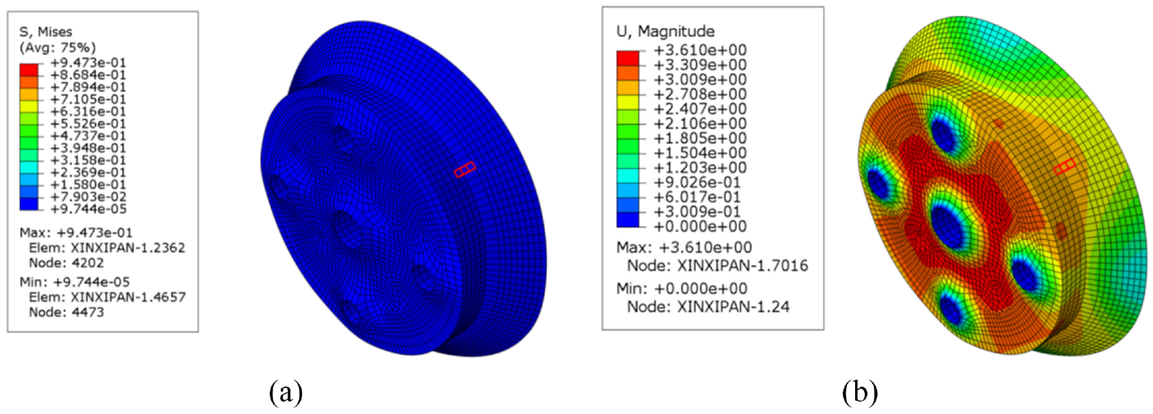
(a) Distributions of the von Mises stress in the horizontal direction and (b) distributions of the displacement in the horizontal direction.
Discussions
To maintain the sufficient absorbed force of the vacuum sucker, it is flexible and made of rubber material. It causes that the vacuum sucker is deformed on the action of the external force.
It is concluded that, when the conversion is operated from the horizontal to the vertical attitudes for the GWS absorbed by the VSAM, the position of central axis of the GWS is deviated.
According to the aforementioned simulating results by the FEM, the maximum vertical displacement of the vacuum sucker is 12.32 mm and the maximum displacement is 3.61 mm in the horizontal direction.
The estimations from the simulations by the FEM becomes the positional compensation of the machine-vision positioning system. In this study, the vertical and horizontal compensated displacements of the vacuum sucker are set by 12.32 and 3.61 mm, respectively, to realize the positional compensation of the positioning system.
Machine-vision positioning system
In terms of the detecting images by the digital camera, which is mounted on the end of the VSAM, the machine-vision positioning system is served for the steel round bar sawing machine to identify the position of the central axis of the hex nut in the working space. In addition, the planning trajectories of motion of the six-axes mechanical arm system for transporting the GWS are also developed according to the positioning results provided by it. The detail setup of the machine-vision positioning system for the intelligent robotic replacement system of GWSs has been reported in Qiu et al. 28 The following is a brief description of the performance.
The program of the machine-vision positioning system was developed in VS2019 environment, which is the man-machine interface (MMI) designed software setup in the WINDOWS operational system. The image processing algorithms are programming by the C# language associated with the MVTec HALCON 18.11 machine vison library, which is the supporting software library for the image processing. The motion planning of the robot arm is performed in the ABB RobotStudio 6.08 compilation environment.
On the algorithm for determining the position of the central axis of the hex nut, the procedures are summarized as follows. The details are omitted here and refereed in Qiu et al. 28 for the simplicity of the manuscript.
(1) The projection matrix between the image coordinate system in the digital camera and the coordinate system in the working space is identified in advance. In this study, the coordinate calibration method developed by Zhang was applied.28–31
(2) In this study, the template matching approach28,32–34 was used to evaluate the position of the central axis of the hex nut. The images of the hex nut captured by the digital camera are firstly operated the image pre-processing. The processes of image pre-processing include the image acquisition, filtering, and enhancement.
(3) Applying the template matching approach, the estimation of the central axis coordinates of the hex nut is obtained from the image pre-processing results by means of the following steps.
Step 1: The circular region, which includes the hex nut, is marked from the image pre-processing results. The marked region is carried out the image gray processing to build the region of interest.
Step 2: The image template of the hex nut is created by clipping the region of interest in the step 1.
Step 3: The image pyramid construction28,35 of the created image template is built.
Step 4: The template model of the shape for the hex nut is setup.
Step 5: The captured image is carried out the image gray processing in advance. Then, the template matching algorithm with the least square algorithm is operated. The matching results are to evaluate the positional coordinates of the central axis for the hex nut.
System architecture, control flow chart, and realistic test
In the aforementioned sections, the overall structure and the main modules of the MIRRS is described. For completing the task of the replacement between the old and new GWSs, the MIRRS is mainly constituted by the six DOF manipulator, which contains the UTM and the DAM, and the six-axes mechanical arm system, which is setup by the six-axes robot arm with the VSAM. Besides, the machine-vision positioning system associated with the digital camera are also built to be served by the MIRRS. The function blocks of the modules in the MIRRS are shown in Figure 4. In the section, the hardware system architecture, the control flow chart, and the realistic testing results are reported.
System hardware connection architecture
In this study, the reported MIRRS is the supporting equipment of steel round bar sawing machine, which is located in the harsh industrial site. To avoid the effects of the external disturbance, the Siemens programming logic controller (PLC 1511-1) is applied to be the control kernel. All the drivers of servomotors and pneumatic cylinders as well as the various sensors are connected with the Siemens PLC by the CAN-bus. The hardware modules, including the digital cameras, the work station (PC), the Siemens PLC, and the ABB IRB6700-150 robot arms, are communicated by the industrial Ethernet. The specific system hardware connection architecture is shown in Figure 23.

System hardware connection architecture of the MIRRS.
Control flow chart
The starting signal of the MIRRS is generated by checking the wear status of the working GWS in the steel round bar sawing machine. When the diameter of the GWS is decreased from 1200 to 700 mm due to the sawing wear, the signal to replace the GWS is generated by the control system. In Figure 24, the detail of the control flow chart is depicted. The main operations of control flow chart in the MIRRS are summarized below.
Operation 1. When the signal of the replacement of GWS is received by the PLC. The six-axes mechanical arm system is controlled to move and the digital camera on the end of it is starting the detection of image for the machine-vision positioning system.
Operation 2. The positions of the central axis of the hex nut and the old GWS is computed and provided to the control system.
Operation 3. The UTM is controlled to the working position. Then, the hex nut is unscrewed by the driving pneumatic wrench. The UTM returns to the initial position in the DAEU.
Operation 4. The DAM is controlled to the dismantling working position. Then, the hex nut is screw out. The hex nut and the flange are removed on the spindle by the DAM. The DAM, which carries the hex nut and the flange, moves backwardly to ready the later assembly task.
Operation 5. When the dismantlement of the hex nut and the flange on the spindle is confirmed, the six-axes mechanical arm system with the VSAM is controlled to remove the old GWS and transport it to the storage place for the discarded GWS. Then, the new GWS is taken and transported to insert on the spindle.
Operation 6. When the accomplishment of the replacement for GWSs is confirmed by PLC, the hex nut and the flange are carried by the DAM and moved to the assembly working position.
Operation 7. The DAM is controlled to finish the installation of the flange and the hex nut insert the spindle. Then, the DAM is returns to the initial position in the DAEU.
Operation 8. The UTM is controlled to the working position. Then, the hex nut is tightened by the driven pneumatic wrench. Then, the UTM is returns to the initial position in the DAEU.
Operation 9. When the task of the replacement is complete, the MIRRS is reset. It is ready to the next task from the Operation 1.
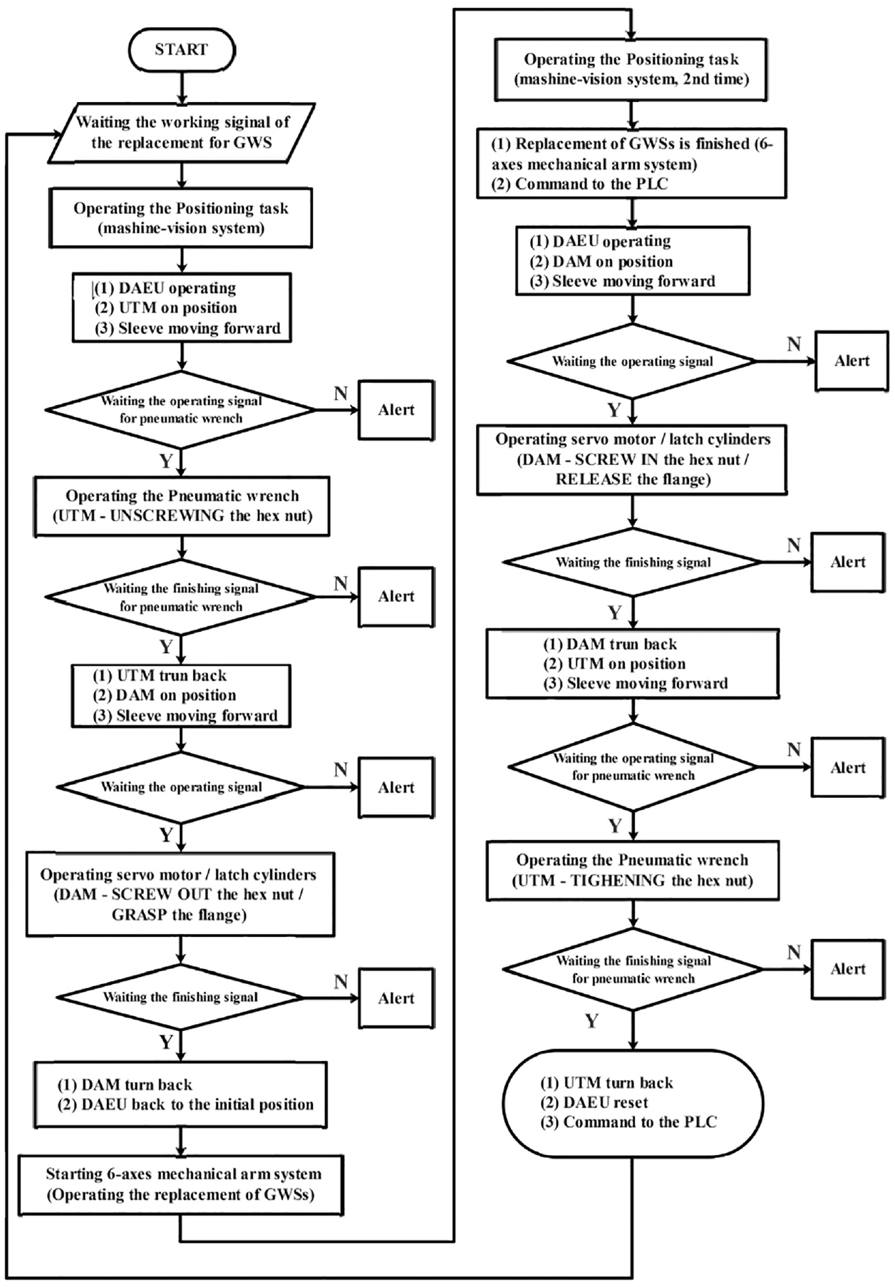
Control flow chart of the MIRRS.
Realistic testing results and discussions
To verify the performance of the MIRRS, the realistic testing of the task for the replacement is conducted. There are the 300 testing results are collected from the records in the PLC. All of the testing results are running without fault in the tasks of the replacement. It further verifies the reliability of the overall intelligent replacement system of GWSs.
The mainly concerns of the 300 testing results are the time of operation durations, which are required for successfully completing the replacement of GWSs by the MIRRS. The 300 total operating durations for the realistic testing are shown in Figure 25. The average total operating duration is calculated as 421.0 s. Compared to the manual replacement for the GWSs, which is taken more than 30 min to finish the task, the MIRRS offers the excellent working efficiency.

Three hundred total operating durations of the realistic testing.
The average total running time is divided by four stages to analyze the performance. It is shown in Figure 26. The percentages of the durations of dismantling and assembling the hex nut and flange, and the durations of removing and installing the GWSs are depicted in the figure as 59%, 34%, 4%, and 3%, respectively. It is concluded that the largest time-taken in the task of replacement is occurred in the mission of dismantling the hex nut and flange on the spindle.

Percentages of time durations of four stages of the replacement.
Conclusions
For the steel round bar sawing machine in the factory, the machine-vision-based intelligent robotic replacement system (MIRRS) of the grinding-wheel-saws (GWSs) has been addressed. The concluding remarks are given in the following.
(1) The developed system mainly includes the six DOF manipulator, the six-axes mechanical arm system, and the machine-vision positioning system.
(2) The six DOF manipulator contains the unscrewing and tightening module (UTM) and the dismantled and assembly module (DAM). It can disassemble and assemble the hex nut and the flange on the spindle.
(3) The six-axes mechanical arm system involves the six-axes robot arm with the vacuum sucker adsorption module (VSAM), whom the tasks of absorption and transportation of GWSs are finished by.
(4) The hardware system architecture and the control flow chart are provided in detail.
(5) The realistic testing results are taken to verify the reliability and offer the well working efficiency.
Footnotes
Acknowledgements
The authors also acknowledge the supports from the University of Science and Technology Beijing and the School of Mechanical and Electric Engineering, Sanming University.
Handling Editor: Chenhui Liang
Declaration of conflicting interests
The author(s) declared no potential conflicts of interest with respect to the research, authorship, and/or publication of this article.
Funding
The author(s) disclosed receipt of the following financial support for the research, authorship, and/or publication of this article: This work was supported in part by the Major Science and Technology Projects of Fujian Province (Grants no. 2022HZ026025 and 2023T0101), the Projects for Department of Science and Technology of Fujian Province (Grants no. 2020-H-0049, 2021-H-0060, and 2021-G-02013), the Program for Innovative Research Team in Science and Technology in Fujian Province University, the Production and Research Collaboration with Innovative in Key Scientific and Technological Project of Sanming City (Grant no. 2022-G-17), and the Operational Funding of the Advanced Talents for Scientific Research (Grants no. 19YG04 and 19YG05) of Sanming University.