
Abstract
This work presents the eigenfrequencies of a study on the fluid-structure interaction for a pipe with a circular section, under pressure constraints in laminar, incompressible and irrotational flow, followed by a comparison between stiffness coupling and bar coupling with different geometric ratio Radius/Length; Radius/Thickness, as a frequency geometric identity of the pipe in the industry. The realization of this study is to have better coupling, where we use the relations of mechanical behaviour of the solid on displacement-stress and for the fluid, we use the Navier-Stokes equations in cylindrical coordinates under the speed-stress form transformed into displacement by the Galerkin-Temp theory. Either the force of the fluid will be distributed on the internal surface of the cylinder by the coupling (interface) between fluid and solid. To obtain the results of the eigenfrequencies we used the hierarchical finite element method (HFEM) for both mechanical and fluid entities. For the natural frequencies, we apply the hierarchical finite elements of the Legendre polynomial which is defined in a well-known interval, thanks to this mathematical calculation we arrive at the general equations of motion matrix form of the solid, the interface and the fluid. The calculation was carried out by a MATLAB programme which determines the eigenfrequencies of the evolved system by different geometric and physical parameters mentioned. We validated this work by a table of comparison between the experimental values and the values of the programme.
Keywords
Introduction
The fluid-structure interaction is the behaviour between the mechanics of fluids and that of the solid by action and reactions to the stresses applied to each other by natural or industrial influences on the flow inside or/and outside of the structure and is the phenomenon in it by all the sides of our industrial life, on the vibration which is propagated continuously and arbitrarily, causes the structural destruction in the movement of the fluid in the pipe.
There are several modes of mechanical contact between two media of different or identical natures. The patterns of this rubbing contact can be considered penetrating or non-penetrating. The particularity of the contact problem requires the knowledge of information on the geometry at the level of the boundaries: distance between two nodes, tangential velocity, fluid pressure and the existence of friction or the nature of the contact under study (Figure 1). 1

Representation of normal contact.
We will establish the continuity of the work of Hicham et al., 2 by a new coupling method with the search for less frequent possibilities at different values of the ratios between radius / length and radius / thickness of interaction fluid structure by the finite element method hierarchical as the method of numerical resolution of a cylindrical structure with circular section conveys a non-turbulent laminar fluid, incompressible cylindrical coordinated irrotational, which depends on the polynomial of modelling used. Quite simply it is the h version instead of the p version which does not require a lot of storage space for the convergence of less convergence time, and also minimizes the chosen finite element refinement followed by the degree of freedom of the polynomial of legend which is presented by Nguyen et al., 3 The convergence of our work has been validated by the work of Zhang et al., 4 for then passing to the study of the method used which gives good compatibility between the experimental values and the hierarchical method, which now also uses the speed polynomial in this domain with different possible boundary conditions (single-single, integrated-integrated, free-free, simple-integrated, integrated-free, integrated-simple) to arrive at the minimum natural frequency of the system. We arrive at the final matrix form of the solid and fluid movement by the temporary Lagrangian approach of the uniform fluid by the principle of virtual works with the Eulerian approach of the solid. We will be interested in a geometrically deformable body which is cylindrical, adapted to the chosen boundary conditions with the physical properties modelled by a stress-displacement relation of the pipe, or the Navier-Stokes equation is modelled in stress-velocity and integrated by Newmark’s method which gives us homogeneity to the equation of fluid motion by the penalty coupling in the form of a bar or the influence of the negligible mass which is linked to the cylinder inside. In all this, we develop a programme under MATLAB, validated by several studied examples, to solve the problem of fluid-pipe interaction with different variables of geomatic parameters concerning natural frequencies.
The majority of researchers who are published on the fluid-structure interaction apply the finite element method like Causin et al., 5 to solve the differential equations in simulation with the different approaches of the possible methods, which brings us to plan a lot of time to arrive at the convergence or the resolution of the problem by refinement but on the other hand, one finds the method of the hierarchical finite elements by Houmat, 6 which succeeds the method of the finite elements or one adds a polynomial of different degrees of freedom instead of refinement (HFEM) by Ouissi and Houmat, 7 it is economical from the point of view of storage (minimization of finite elements) and resolution (minimization of the size of the matrices of stiffness and mass) a simple algorithm, or most works do not practice this method on the domain of fluid-structure interaction.
We will highlight some work that has been carried out in the field of fluid-structure interaction with a quotation of the coupling used in these articles on the vibration side or the eigenfrequencies obtained for cylindrical pipes carrying fluid. Among these works we find in the study of Alshabatat, 8 which seeks to optimize the natural frequencies of cylindrical shells with thin walls for materials with variable gradient in the longitudinal direction by the trigonometric law of volume fractions which uses the finite element method to modify the stiffness and mass of the structure by the theory of shear deformation formulated by Hamilton’s principle. This validation by the p-version of the element to have compatible values that take a lot of convergence time to refine 36 × 40 elements. Duan et al., 9 use the finite element method to study the modal analysis of tubes at high temperature and high pressure to apply the fluid-structure interaction (coupling) of a way where the force of the fluid equals the force of the solid in the form of an inertia matrix to arrive at the dynamic equation of the system which gives a decrease in the eigenfrequencies if there is greater displacement, also the more the pressure increases it there is an increase in the stresses which also gives a low natural frequency for the tube because the higher the temperature, the lower the natural frequency. This time Mi and Zhou, 10 applied Galerkin’s method for a cylindrical pipe carrying an internally flowing fluid composed of oil-gas-water at different viscosity values to influence natural frequencies with critical velocities found with the coupling uses added mass types in the vibrational kinetic equation of motions, also Wu et al., 11 studied the underwater vibrational causes of a shaft pipeline submarines where they used ANSYS software for geometry then reported in Fluent for vibration analysis and pressure distribution with subsea pipeline velocity. They applied the Navier-Stokes equation following the standard k−ε turbulent model for the state of the moving fluid in the pipeline in this work which is based on the finite element method FEM, on the other hand, Selmi and Hassis, 12 studied the natural frequencies of the three modes in the vibration analysis on a pipe in graded material which transports fluid. The material properties are assumed to be graded in the thickness direction after solving the problem and obtained by buckling deformation with various boundary conditions. Whether the influence of the speed and the density of the fluid in free vibration is sought, also we have the work of Hyvarinen et al., 13 use the experimental software ANSYS by the finite element method FEM for the solid and BEM for the fluid where they will solve their problem by investigating the failure of the hydraulic hose which is dynamic with the presence of the phenomenon of fluid-structure interaction (FSI). They discovered that fatigue in hydraulic hoses comes from modular vibrations or natural frequencies about the speed and pressure of the hydraulics. The works of Wu et al., 14 are also based on the k−ε model of the turbulence with the pressure force added through the convergence time to have the exact solution of the equation of motion to be able to find the natural frequencies of the pipe with different modes from 1 to 5, with the comparison of these experimental and numerical results of the coupling proposed by coherent with the calculation method used to have the effect of the pressure on the vibration of the pipeline. We also find Quan et al., 15 studied the axial vibration responses of the fluid-structure interaction (FSI) for the hydraulic lines of the C919 aircraft where they used the coupling in a model of friction like the contact interface between fluid-structure applying high speeds and high pressures, with of course the presence of the Reynolds number in their calculation. Using MATLAB to find the frequencies of the different characteristic poses in this article is to forget the comparison between numerical and experimental simulation results. Fuster et al., 16 their work applied the Lagrangian method and the Weymouth and Yue (WY) method Euler-implicit method for conservation of mass and momentum of fluids to improve stability and to couple its applied density formulas which vary with incompressible Navier-stokes flow. On the other hand, we find different couplings in previous works such as Guo et al., 17 applied the coupling in the form of a stress-strain relation by strain-displacement contact with the mass coefficients of the solid and the fluid according to a dimensional summation in inverse time which is equal to zero, to ensure the stability of the fluid-piping-flexible interaction for the two methods used FSI-FVM, the different effects of the free supports, fixed and elastic. Also, Cui et al., 18 use a multi-field mathematical model of the fluid-solid-magnetic coupling, based on two bidirectional fluid-solid couplings and a unidirectional magnetic structure caused by the fluid pressure deformation of the weld were obtained by the permutation of the fluid penetrated as a force applied the opening of the internal crack which causes the growth of this crack in the weld of the pipe with a discussion on the field of magnetic in the process of internal crack growth. The works of Liang et al., 19 investigate natural frequencies of fluid velocity, fluid density with the presence of functional gradient materials (FGMs) the volume variation of the internal material by its power gradient for a pipe composed of metal and ceramics the transport of fluid and the proposed coupling it is coupling by the mass added in the form of density multiplied by the volume. Kesimli et al. 20 studied the linear vibration of a fluid transport pipe for single supports of variable position between two supports clamped at the end, or they used the coupling in the form Lagrangian in kinetic energies for fluid and potential energies for the structure of the fluid-structure interaction system. Using Hamilton’s principle of the integral in time which is zero, or the results obtained in graphical form. Also found in work by Xu et al., 21 a Fluid-Structure Interaction (FSI) study applies the coupling that fluid force equals solid force, by models of finite elements of a bent pipe filled with fluid in free vibration at high frequency which meets the kinematic conditions on the interface of the ship by ADINA software. Shows that the results of FSI seriously affect the motor modal frequencies where the liquid reduces the motor frequencies and that the fluid-structure interaction hardly affects the liquid modal frequencies, if the fluid velocity drops towards stability then one has the vibrational continuity of driving and vibration disperses as time increases. Catinaccio, 22 studied the general behaviour of thin isotropic pipes, thick isotropic pipes and straight uniform orthotropic thin pipes with recessed ends, they considered that pipes under internal pressure had a comparison between Timoshenko’s formula ‘Theory of elastic stability’ and The longitudinal force on the pipe, therefore the overall compression/tension force P are approximations based on the small deformations and the incompressibility of the chosen material with the load lateral q. Use of finite elements in ANSYS. In this work, we find another notion of the coupling of the fluid-structure interaction where Küttler et al., 23 gives an idea of the coupling where the incompressible fluid contains internal stresses defined by Navier-Stokes equation where the considered fluid is assumed to be Newtonian, its coupling depends on the distance between fluid and solid by the Dirichlet-Neumann iteration or it can be found in the article by Klöppel et al., 24 which is based on Cartesian coordinates as a limit condition of the contract to obtain the possibility of applying the balloon deformed by time.
Mathematical formulation
Structure
Consideration is given to the fluid-structure interaction of a cylindrical pipe of circular section which transports fluid of diameter D, of internal radius R1, external R2 of length L, thickness h of a flow at internal pressure P over the entire length of the tube as shown in Figure 2.

Cylindrical to internal pressure.
By relating the stresses to the deformations, the anisotropic, orthotropic and isotropic materials will be considered, except in the case of one-dimensional elements (axial, torsor and beam) where only the isotropic case is treated. The state of strain in an elastic body is defined by the strain components.

If the displacement components in the directions of the axes are denoted by

Consider a transversely isotropic elastic solid cylinder of constant section. The isotropic plane of the material is perpendicular to the axis of the cylinder, which is considered to be the same as the z-axis of the cylindrical coordinate system (r, θ, z), see Figure 3.
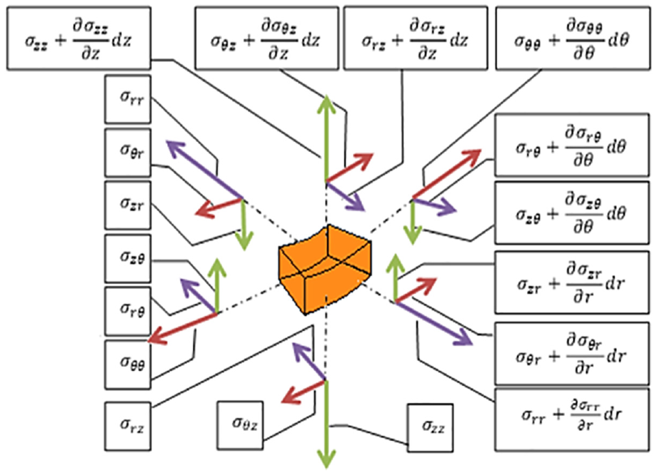
Constraint in cylindrical coordinates.
The stress (

where C66 = (C11−C12)/2 and
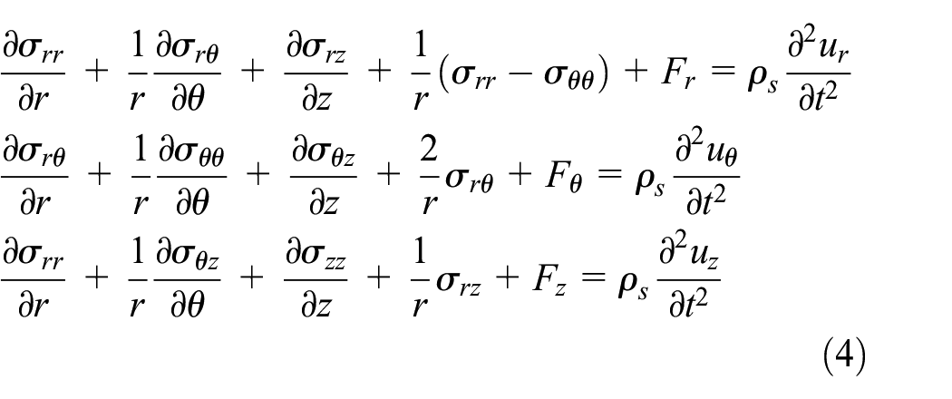
Where ρ is the density and t are the time variable. Unlike the conventional displacement method 27 which eliminates the six stress variables σij from equations (3) and (4) to obtain three second-order coupled partial differential equations around the three displacement components ui, the state space approach generally keeps three stress components and three displacement components and transforms the governing equations into a set of first-order ordinary differential equations concerning a particular coordinate variable. The state-space approach has particular advantages over the displacement method in solving certain kinds of mechanical and engineering problems, and the interested reader is referred to Chen et al. 28 for more details and references. Where [D] is the matrix that links the displacements and deformations. The stress-strain relationship takes the Hooke form:

Where [D] is a symmetric matrix. An anisotropic material, it contains 21 independent material constants. In the case of an isotropic material, it is:

Fluid
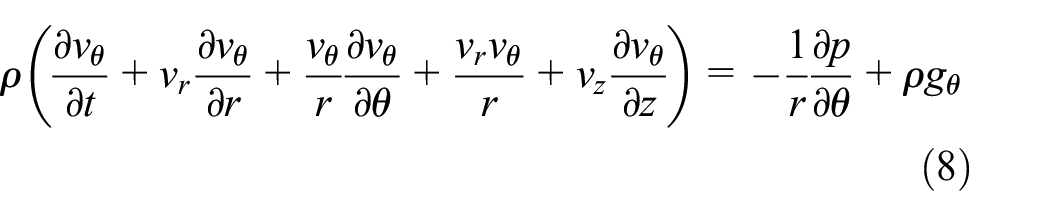
The basic equations of fluid dynamics are called Navier-Stokes 29 equations. In the case of an isothermal flow, that is to say, a flow at a constant temperature, they represent two physical laws of conservation: the conservation of mass and the conservation of linear momentum. There are different ways to derive these equations. The flow will be described with the variables which are supposed to be sufficiently smooth functions in the time interval [0, T] and the domain Ω⊂R3.
ρ(t,x): volumic mass [kg/m3],
v(t,x) : velocity [m/s],
P(t,x) : pressure [Pa = N/m3],
The Navier-Stokes (N-S) equations 30 are the widely applied mathematical model to examine changes in these properties during dynamic and/or thermal interactions. The equations are adjustable according to the problems to be simulated and are expressed based on the principles of conservation of mass, momentum and energy:
➢ Conservation of mass: continuity equation.
➢ Conservation of momentum: Newton’s second law.
We consider an incompressible isothermal Newtonian
31
flow (density ρ = constant, viscosity μ = constant), with a velocity field


It was also called the mixed finite element method. To present how to deal with this difficulty, let us recall that the pressure acts as a Lagrangian multiplier of the incompressibility constraint. Then, the algebraic system for the nodal values of velocity and pressure in a Galerkin formulation 32 will be governed by a partitioned matrix with a zero submatrix on the diagonal. The resolution of the algebraic system depends on an appropriate choice of finite element spaces for velocity and pressure. To better understand how to deal with the difficulty of the incompressibility condition, the procedure of the finite element method based on the formulation of primitive variables will be presented step by step. We will start with the discretization of the incompressible Navier-Stokes equation in weak form using the weak formulation. Next, the selection of finite element spaces for velocity and pressure will be discussed.
The application of the Galerkin method (PTV). 33


Discretization
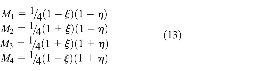
The eight-node hexahedron element is a generalization of the bilinear quadrilateral element. Under a tri-linear transformation, the reference element (unit cube; Figure 4) defined in the space η, ζ, ξ is the image of the domain Ωe defined in the space x, y and z. The basis of the vector space generated by polynomials of degree 1 is {1, ξ, η, ζ, ξη, ηζ, ξζ, ξηζ}. By using the properties of the shape functions, we deduce the expressions of the shape functions.
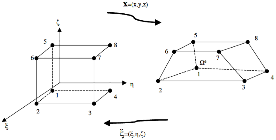
Tri-linear hexahedron element.
From the shape, we deduce the expressions of the shape functions. Spatial functions for the HFEM approximation of the velocity component become 34 :

Spatial functions for pressure approximation:
Cylindrical vibration by the HFEM method
From the conditions of the choice the finite element, whatever is in 2D or 3D, applies the hierarchical finite element (HFEM) of it replaces the nodes 5, 6, 7 and 8 of the element of Taylor-Hood by polynomial bar following an interpolation to be established by the legend function 35 which is defined as follows:

Which satisfies the orthogonality relation
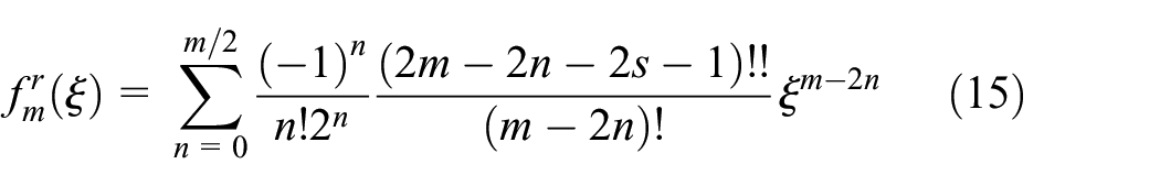
With

The orthogonality of the polynomial of Legendre Groen et al. 36 in the interval [−1 1], is made by integration, and all their lower order derivatives disappear at ξ = ±1, we obtain the following result numerical formula Babuška et al. 37
The H-FEM can be used to calculate the vibration characteristics, point displacements of a cylindrical shell or the tangential components vr, vθ, vz, of the normal component. The routes are given by:

Couplings between fluid and structure FEM-FEM penalty method
The non-zero components of matrix B are displacements of the gradients ξ or η, in which the directions of the nodes of displacement its resultant in the tractions and displacements relating to the central point of integration. In this class of interface elements, displacements relative to the n pairs of nodes are used instead of a field of relative displacement interpolated in integration points. The element stiffness matrix is now expanded as:

where the matrix

and Ai, the i-node surface. The sub-matrix

Bien évidemment, aucun couplage n’existe entre les degrés de liberté des différentes paires de nœuds. On note que les éléments d’interface à intégration localisée sont proches des éléments d’interface dits nodaux ou ponctuels (
The FEM-FEM penalty method 38 is characterized, on the one hand, by the link that exists between one the structure element and one fluid element, and, on the other, by the stiffness at the interface; the radial force at the interface can therefore be determined. In the present work, the stiffness is represented by a bar in order to take into account the axial force at the interface, in addition to the radial force, as clearly shown in Figure 5.
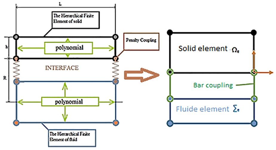
FEM- FEM spring coupling and bar coupling.
The method used consists in arranging dummy bars, at the interface, capable of generating radial and axial forces penetrating the contact surface, for all the nodes. The equilibrium position of these bars corresponds to a slave node positioned on the master segment. The forces are determined by:


This approach makes it possible to determine the equation of motion as follows:

The boundary conditions are defined with respect to the solid and the fluid. The boundary conditions in the case of the solid are:

The boundary conditions in the case of the fluid are:

Since the interaction occurs between the fluid and the structure, the action-reaction law imposes the equality of the two expressions (23) and (24).
Therefore, one can write 39 :

And

The contact forces in the penalty case are determined by:

αp is the penalty factor.
To determine the quantities

To check the penalty coupling condition,
40
it is necessary that the ratio

The multiplication of the matrices

whith:

The matrix

It should be noted that αp must be between 104 and 109;
Equation of motion
The potential energy of the structure is given by:
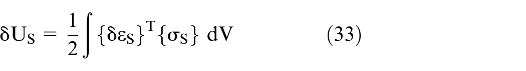
The expression (33) for the cylindrical shell, in cylindrical coordinates, may be expressed as:

For a solid to be in equilibrium, the work of the external forces must be equal to the kinetic energy:

The elementary kinetic energy is given by:

The application of the principle of Hamilton 42 allows writing:

This then makes it possible to obtain the equation of movement of the structure.

The stresses due to the displacement of the fluid, 43 as determined by the Navier-Stokes equation, are given by the following relation:

The equation of motion of the fluid is given by 44 :

The Navier-Stokes equation (38) contains strong variational terms. The Galerkin method is applied in order to weaken the formulation for the numerical discretization. In addition, both equations (37)and (39) are used to find the equation of motion for the coupled system in the following matrix form:

The equation of motion of the entire system is determined in terms of the radial, circumferential and axial displacements in the cylindrical coordinate system (r, θ, z). The free vibrations of the components
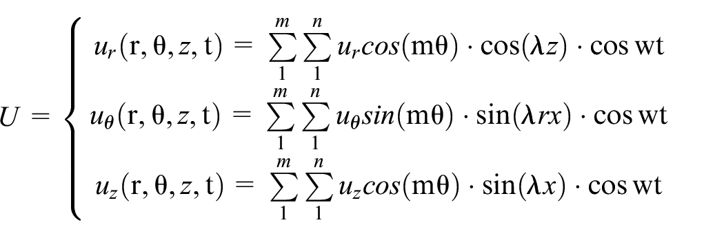
Where
The coefficient λ is determined from the boundary conditions:
- Cylinder supported at both ends
- Cylinder whose ends are embedded
Validation
A programme, which allows obtaining the natural frequencies of the pressurized cylinder with a fluid flow, was developed. It was validated by studying its convergence and the results obtained were compared with those reported by other researchers.
Convergence
The study of convergence is clearly shown in Figures 6 and 7.

Convergence for different degrees of the polynomial: Case of the solid.
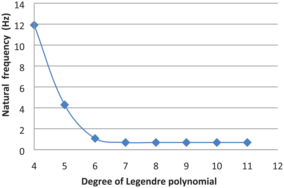
Convergence for different degrees of the polynomial: Case of the fluid.
Comparison of results
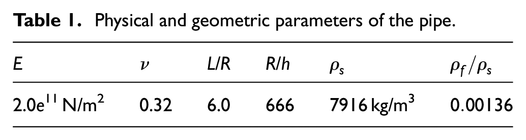
The eigenfrequencies and the eigenmodes of vibration of the pipes containing the fluid are determined. The physical and geometrical parameters of the pipe are given in the following Table 1 of the system clamped–clamped boundary.
Physical and geometric parameters of the pipe.
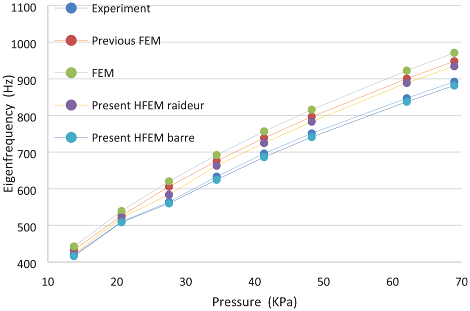
The eigen frequencies of the pipe are determined as a function of the pressure variation for the first longitudinal mode and for different circumferential modes. The results obtained are compared with the experimental findings
47
and those found numerically by the FEM
48
and Zhang et al.
49
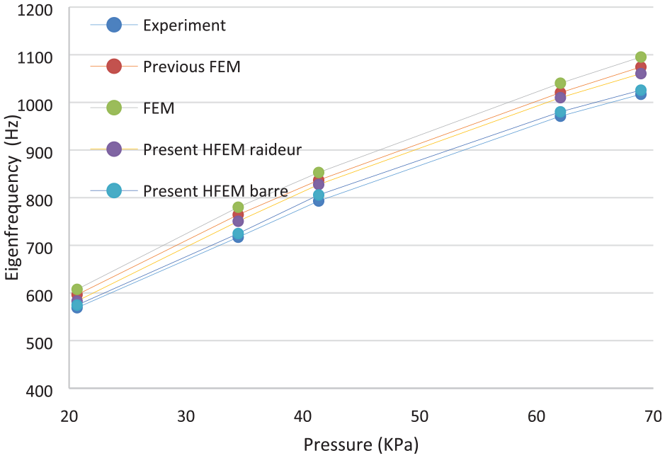
; they are given in Table 2 and illustrated in Figures 8 to 10. The percentages of errors
Validation of the model.

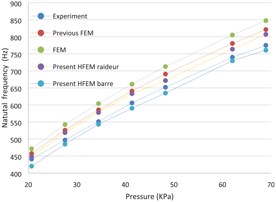
Variation of frequency versus flow pressure, for m = 1and n = 7.
Variation of frequency versus flow pressure, for m = 1 and n = 8.
Variation of frequency versus flow pressure, for m = 1 and n = 9.

Relative error
Figures 8 to 10 clearly show the similarity between the results obtained from a bar coupling model and the experimental ones.
Case study
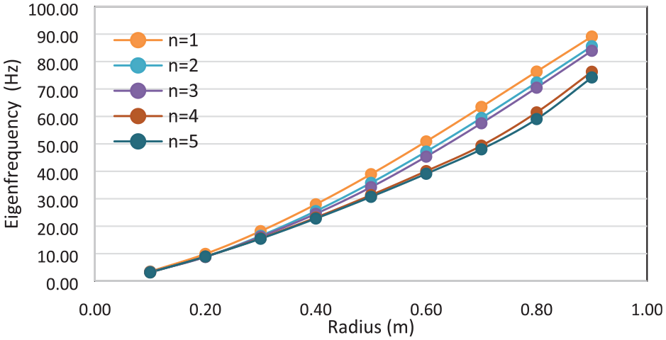
After the validation of our work in being able to establish a graphic study of different geometrical parameters according to the applied coupling (bar and spring) with a frequency graphic presentation of Figures 11 to 16, we use different circumferential and longitudinal modes on the structure and fluid as we show on the theory part of the equation (42). This study allows us to have a general idea about the behaviour of the coupling between the natural frequencies as a function of the length and the radius of the pipe, as it is followed by a graphic appearance between the natural frequencies of interface (coupling) stiffness and bar or finds that the natural frequencies of stiffness rise than the natural frequencies of the bar with increasing pipe length, but when changing radius, the reverse occurs where the natural frequencies of bar rise than the natural frequencies of cylinder stiffness. We allow saying that the coupling by bar gives results close to the reality of the natural frequencies that coupling by stiffness which absorbs the applied forces of the fluid which causes damping for frequential (minimizes the frequencies to its real value) therefore we can say that the interface of the bar and perfect for coupling between solid and frequential fluid. As shown in Figures 12 to 17.
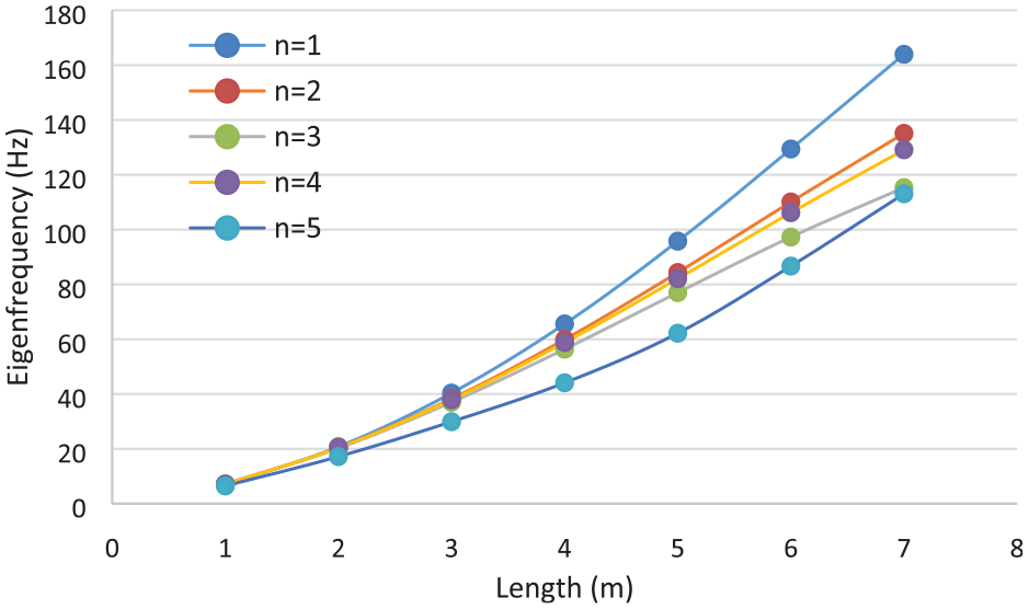
Variation of the eigenfrequencies of the bar coupling as a function of the length for the different longitudinal modes or the constant circumferential modes m = 1.

Variation of the eigenfrequencies of the stiffness coupling as a function of the length for the different longitudinal modes or the constant circumferential modes m = 1.

Comparison of frequency variations versus pipe length for the cases spring coupling and bar coupling with m = 1.
Variation of the eigen frequencies coupling stiffness versus pipe radius with m = 1.

Variation of the eigen frequencies with bar coupling versus pipe radius m = 1.
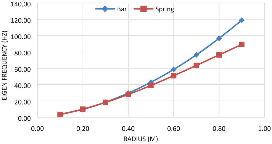
Comparison of eigen frequencies by versus pipe radius for spring coupling and bar coupling (mode m = 1, n = 1).
Results interpretation
When we found the opposite behaviour from the results obtained previously between the natural frequencies of the coupling stiffness and bar share ratio the variation of the length and the radius made it possible to make a study on the eigenfrequencies with the different possible geometric ratio between Radius /Length, Radius/Thickness (R/L, R/e) to have a frequential analytical explanation on this behaviour of the bar coupling, then we carried out a study for which we left all the physical parameters of the validation in such a way facilitates us to conclude the results that we obtain.
This is the reason why we change the ratios from R/L = 1 to 7 and from R/e = 0.002 to 0.14 where we found that the influence of the geometric ratios on the dynamic behaviour of the system of fluid-structure interaction from the natural frequency contains significant because there is a sudden decrease between 0.1 and 1 m then follows the increase of these natural frequencies up to the 7 m length of the pipe, also the frequencies decrease when the ratio between Radius/Length and Radius/Thickness increase as shown in Figures 18 to 20. For different longitudinal modes at constant circumferential mode. This presentation allowed us to conclude that the less frequent part varies between 0.01 and 1 m these or can choose the less frequent pipe for the industrialist.

Variation of the frequencies of bar coupling versus pipe length with mode m = 1, n = 1.

Variation of the frequencies of bar coupling versus pipe length with mode m = 2, n = 1.
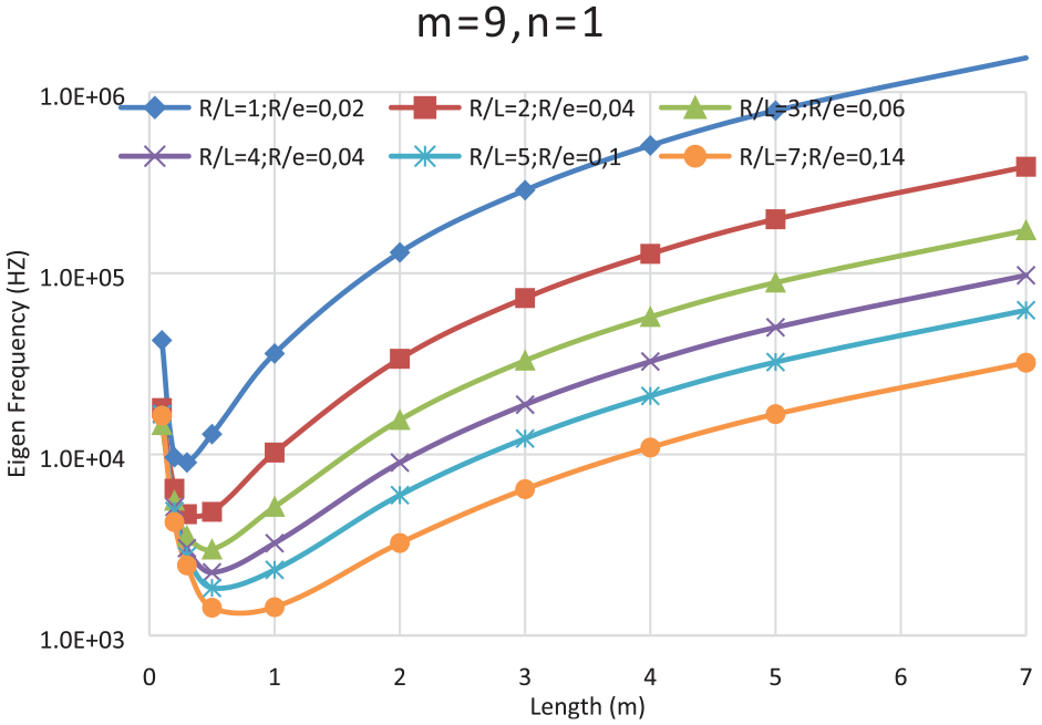
Variation of the frequencies of bar coupling versus pipe length with mode m = 9, n = 1.
Case study
Several examples have been considered to study the influence of geometric parameters in the two cases of stiffness and member coupling. Showing us some of the results obtained are shown in Figures 18 to 20.
Conclusion
In this work, a new model of penalty coupling is proposed where the spring element of the interface is replaced by a bar. This model makes it possible to take into account the effect of the radial contact and that of the axial forces. In this study, the model of the case of an internal pressure cylindrical pipe with incompressible laminar flow is applied, of an internal pressure cylindrical pipe with incompressible laminar flow; this was possible by modeling the system using the hierarchical finite element method.
The behavioural equations were determined using the principle of virtual work for the solid, and the Navier-Stokes equations for the fluid. Modeling of the structure-fluid system was done by the hierarchical finite element method using a finite element of the rectangular four-node type with three degrees of freedom per node. A MATLAB programme was developed to calculate the natural frequencies of the pipe carrying the fluid.
The comparison between the results obtained by our programme and the experimental ones indicates that the bar coupling is better than the spring coupling.
In addition, some case studies were carried out and the results obtained are illustrated in a number of graphs which represent the influence of the different geometrical and physical parameters on the eigenfrequencies, in the case of the two types of coupling, i.e. bar coupling and spring coupling, for the fluid-structure interaction phenomenon.
The following conclusions may therefore be drawn:
- The results obtained using the bar coupling model are very close to those obtained experimentally.
- Increasing the diameter of the pipe, with constant thickness, increases the stiffness of the structure. Also, as the thickness of the pipe increases, the stiffness of the structure goes down. In the presence of the fluid, the mass of the structure rises.
- Increasing the pipe length leads to lower structural stiffness, for the different circumferential modes.
- Finally, increasing the pipe length results in a decrease in the structural stiffness, for the different circumferential modes.
Footnotes
Handling Editor: Chenhui Liang
Declaration of conflicting interests
The author(s) declared no potential conflicts of interest with respect to the research, authorship, and/or publication of this article.
Funding
The author(s) received no financial support for the research, authorship, and/or publication of this article.