
Abstract
The passive suspension seats have been widely used in off-road vehicles, but the drivers still suffer from the greater vibration and shock transmitted from the rough road, adversely affecting the drivers’ health and vehicle handling safety. Although active suspension seats have been researched and developed in engineering and academia for more than 30 years, they have rarely been applied in the industry due to the complex electrical structures and high costs. In this paper, a novel valve damping control system (VDCS) used in the off-road vehicle seat suspension is proposed and studied, which is a mechanical semi-active damping control system without ECUs and sensors. Firstly, the structures and working principles of VDCS are described in detail. Then, the dynamics model of the seat suspension system with VDCS is established, and simulation and experimental research are performed to evaluate its shock and vibration isolation performance. The results show that a seat suspension with VDCS is much better for isolating vibrations and shocks than one with a traditional manual adjustment damper in the whole workspace.
Keywords
Introduction
When an off-road vehicle is operated, the driver suffers from seat vibration and shock induced by the uneven road, propagated through the chassis and cabin suspension. The dominant vibration and shock are mainly in the vertical direction and at 1–20 Hz. Since the frequency range covers the natural frequency of the human organs, the resonances of human organs are inevitable. Long-term harsh vibration environments may cause musculoskeletal diseases, such as low back pain, fatigue, spinal disorders, and other gastric complaints. Meanwhile, the vibration and shock prevent the driver from concentrating on the operation of the vehicle, thus posing a safety risk.
The traditional seat cushion can not effectively isolate the vibration in this frequency range (1–20 Hz) but supply the proper support to the human body. Therefore, the passive suspension seat1,2 with a lower natural frequency (less than 2 Hz) has been developed, usually composed of the air spring, the damper, and the scissor guide mechanism. In order to achieve the perfect comfort performance, the seat suspension should have lower dynamic stiffness to reduce the high-frequency acceleration from the cabin to the seat cushion. However, the lower dynamic stiffness may give the seat suspension a significant dynamic deflection at the low-frequency and high-amplitude road-induced vibration excitation. In this large deflection case, the driver’s feet may frequently be out of reasonable reach of the accelerator and brake pedals of the vehicle, resulting in operation difficulty.
Moreover, the sizeable dynamic deflection may cause the seat suspension to exceed the stroke limitation, hit the lower or upper end-stop buffer of the seat suspension, and deteriorate the seat comfort performance undesirably. Consequently, there are a couple of conflicts in the scissor suspension seat design: reducing the operator’s vibration acceleration and decreasing the dynamic deflection to control the vehicle effectively. The seat suspension design is a complex compromise, where the following three objectives need to be included: minimizing the acceleration transmitted from the cabin floor to the seat; minimizing the dynamic deflection of the seat suspension; and reducing the occurrence of the seat suspension hitting the lower and upper buffer.
For more than three decades, the vibration isolation principles and optimal design of passive suspension seats have been a popular topic in engineering and academia to solve these design conflicts effectively. Wu and Griffin 3 defined the seat suspension performance as five stages based on the increasing amplitude of the input vibration excitation. There exist different requirements for the damping and stiffness of seat suspension in different stages. Gunston and Annex 4 pointed out that reducing the viscous damping slightly affects comfort performance improvement at the low and moderate amplitude vibration but leads to a sizeable detrimental effect at the significant amplitude vibration since the increased occurrence and severity of end-stop impacts. Ideally, the friction should be reduced as much as possible, and the viscous damping should be used to control the occurrence of end-stop impacts. Stiles et al. 5 found that 45% of the suspension seats increased the vibration levels when the driver operated the off-road vehicle. The main reasons were the occurrence and severity of the end-stop impact.
Undoubtedly, the passive vibration isolation suspension seat is the simplest, low-cost, and most reliable solution to protect the off-road vehicle driver from the harsh vibration environment. However, the passive seat suspension is unsuitable for the seat in various vibration excitation conditions induced by rough roads and drivers of different masses. In order to overcome the shortcomings of the passive suspension seat, the semi-active seat suspension,6,7 and the active seat suspension, 7 have been studied and successfully fulfilled. The active seat suspension system is a more efficient vibration isolation system. There are various methods to implement active control, such as using conventional linear actuators like hydraulic cylinders or linear motors, pneumatic actuators, and rotary electric motors. However, the active seat suspension system is rarely applied because of its high cost and complex structure. 7
To simplify the structure of the active seat suspension, some researchers 7 presented the electronic control semi-active suspensions without the actuators in the active suspension. Semi-active suspension system adjusts stiffness and damping to improve suspension performance in vehicles. Recent research has proposed some novel solutions for variable stiffness and variable damping synchronously by connecting a spring and adjustable damper in series and utilizing a changeable damper in parallel.8,9 This paper specifically focuses on researching changeable damping in seat suspension. By utilizing feedback signals obtained from sensors that directly measure relative velocity and relative displacement, the semi-active suspension system drives the on-off or continuously adjustable damper, resulting in improved comfort performance of the suspension seat. Duke and Goss 10 developed a non-linear suspension seat with an on-off hydraulic damper. The experimental results indicated a 40% reduction in the root-mean-square (r.m.s.) acceleration compared to the linear passive damping seat suspension, and the end-stop impacts disappeared simultaneously. Rakheja and Sankar 11 presented an on-off semi-active control system by adjusting the orifice area of the traditional hydraulic damper. It was found that the time delay associated with switching the solenoid and hydraulic on-off valve of the damper may significantly influence the performance of the vibration isolation. Wu and Griffin 12 developed an on-off semi-active control strategy to decrease the severity and occurrence of the end-stop impacts caused by the shocks and high amplitude vibration. They used the MR damper, which had high complexity and high cost, instead of the traditional hydraulic damper to achieve the on-off, two-state damping. The complex electronic control system and higher cost limit the popularity of the semi-active control suspension seat. However, the excellent performance of the on-off control strategy with the proper delay-time parameters in the semi-active seat suspension control is fully proven.
The scheme implementing semi-active control is the critical bottleneck to overcoming the above conflicts in suspension seat design and obtaining the suspension seat’s optimal performance. Karnopp et al. 13 developed a semi-active control scheme called the skyhook control that can respond to general feedback signals calculated from the vibrating system’s relative velocity and the relative displacement to control the vibration. It provided one typical example of the theoretical support for the development of semi-active control seat suspension systems. Wu and Griffin 12 and McManus et al. 6 studied the application of the on-off control strategy based on the pre-set relative displacement threshold and found that the control strategy has noticeable effects on preventing end-stop impact and improving vibration isolation performance. Łuczko and Ferdek 14 and Nie et al. 15 introduced a stroke-dependent damper to imitate the characteristics and performance of the semi-active suspension. The stroke-dependent damper can realize the function of semi-active suspension based on the suspension’s relative displacement feedback signal. It is a valuable method because this type of semi-active suspension is a complete mechanical damper without additional hardware, electronic control modules, or sensor components in the suspension system. According to these studies, semi-active suspension based on suspension relative displacement as control input can effectively improve the suspension comfort and reduce the suspension travel. However, this type of suspension can only act as a semi-active suspension at a specific static equilibrium position. The frequent changes of the static equilibrium position of the suspension arising from varying sprung load mass can cause the suspension system to lose the performance of the semi-active suspension frequently.
In the research field of seat suspension, a low-cost semi-active control system without electronic components but with excellent performance for varying sprung load mass and suspension static deflection is urgently required. In response to this requirement, this paper proposes a seat suspension using a novel valve damping control system (VDCS), which may compromise the cost and vibration isolation performance. The VDCS adopts a pneumatic automatic mechanism consisting of some main pneumatic components but no electronic components. The pneumatic valve is used to measure the relative displacement of the seat suspension as the semi-active control input, and the pneumatic cylinder is used to drive the adjustable on-off damper as the semi-active control actuator.
The organization of this paper is as follows. Firstly, the principle and structure of the seat suspension with the VDCS are presented, and then the feasibility analysis of the VDCS is performed through the Simulink simulation model with the WNP excitation signals. Secondly, this suspension’s physical model experiments are conducted with the different vibration excitation signals, such as WNP, EM3, and EM6. Finally, the experimental results are analyzed, and conclusions are obtained.
Principle of semi-active control seat suspension with VDCS
For the seat suspension of the vehicle, higher damping can suppress vibration transmissibility near the resonant frequency, but the vibration isolation performance is significantly reduced under high-frequency vibration input. Lower damping can improve vibration isolation at high frequencies, but the transmissibility near the resonance frequency is dramatically amplified. Meanwhile, seat suspension’s relative displacement increases, causing frequent and severe end-stop impacts. 3
To achieve optimal performance, the control strategy of VDCS should allow the seat suspension to be generally set as a soft damping mode and automatically switch to the hard mode before the event of an end-stop impact, as shown in Figure 1.

The seat suspension system with VDCS.
The control strategy takes the instantaneous relative displacement of the seat suspension as the control input. Therefore, in this paper, the VDCS detects the relative displacement of the seat suspension directly by the pneumatic control valve located in the seat suspension. Whenever the relative displacement exceeds the pre-set displacement threshold, the pneumatic driving cylinder automatically drives the adjustable damper from soft mode (“off” state) to hard mode (“on” state) to prevent the end-stop impact. When the seat suspension relative displacement goes back to the range of the displacement threshold domain, the adjustable damper operated by the return spring automatically delays back to soft mode (“off” state) to improve seat comfort under high frequency and low amplitude vibration excitation.
The control strategy of VDCS can be expressed as equation (1) 12 :

where
Structure and components of seat suspension with VDCS
The seat suspension with VDCS in this paper can be simplified as a planar structure shown in Figure 1. It consists of eight components, the scissor guide mechanism, the upper suspension frame, the lower suspension frame, the air spring, the adjustable damper, the VDCS (including a pneumatic control valve with a seat height control cable and a pneumatic driving cylinder), the upper buffer, the lower buffer.
The novel characteristics of seat suspension with VDCS proposed in this paper are that two pneumatic components (pneumatic control valve and pneumatic driving cylinder) and the adjustable damper could realize the main functions of the on-off semi-active control seat suspension. Furthermore, the VDCS overcomes the drawback of the displacement-dependent damper 14 (having only one working height) by introducing the seat height control cable.
The air spring and adjustable damper are equipped between the inner and outer scissor guide mechanisms to isolate the vibration and shock transmitted from the cabin. The damping adjuster lever of the adjustable damper used to change the damping mode is connected to the piston of the pneumatic driving cylinder. The upper and lower buffers, made of polyurethane material, are fixed on the upper and lower suspension frames separately to decrease the severity of the suspension end-stop impact.
The VDCS is installed between the upper and lower frames of the seat suspension to detect the changes of the pre-set height level of the seat suspension and maintain the pre-set height level of the seat suspension by inflating or deflating the air spring through its pneumatic control valve. Meanwhile, the pneumatic control valve inflates the pneumatic driving cylinder to switch the adjustable damper from the soft mode (“off” state) to the hard mode (“on” state) once the changes of seat suspension height level exceed the pre-set displacement threshold of VDCS control strategy. The given height level of the seat suspension (at a range of around 100 mm) could be manually changed by adjusting the length of the seat height control cable. By increasing the length of the height control cable, the pneumatic control valve inflates the air spring and causes the seat suspension to rise to the target height. By reducing the cable length, the pneumatic control valve deflates the air spring and gives rise to the seat suspension lowering to the new target height. Each seat height level corresponds to a unique length of the seat height control cable. The combination of the height control cable with the pneumatic control valve ensures the semi-active control characteristics of the seat suspension at any pre-set height level.
The seat suspension height level may be set to accommodate different drivers’ heights. When the height level of the seat suspension changes due to the driver’s replacement or shocks from rough terrain, the pneumatic control valve inflates or deflates the air spring to make the seat suspension keep the given height level.
Working principles of pneumatic control valve and pneumatic driving cylinder
The pneumatic control valve is a type of spool valve structure. Figure 2 shows that the pneumatic control valve is mainly composed of the valve block and the valve stem connected with the seat height control cable. The valve block is divided into four chambers (A, B, C, and D chambers) by the sealing ring and the valve stem. The four chambers are connected to the air source, the pneumatic driving cylinder, the air spring, and the atmosphere. Therefore, the relative sliding of the valve stem and valve block may change the four chambers’ connectivity relationships, resulting in air flowing between different chambers. At the same time, these airflows control the air spring inflation or deflation and switch the damping mode by driving the pneumatic driving cylinder. The existence of the seat height control cable ensures that the semi-active control functions of VDCS are still practical at any pre-set height level of the seat suspension.

Schematic and inner structure of the pneumatic control valve of VDCS: (a) schematic of the pneumatic control valve of VDCS and (b) inner structure of the pneumatic control valve of VDCS.
According to the required performance of the pneumatic control valve, an actual sample is developed, as shown in Figure 3(a). And Figure 3(b) describes the five working statuses of the pneumatic control valve. There is no relative movement between the sealing ring and the valve body, and the valve stem is designed with air-flowing grooves on its surface arranged at specific intervals. When the valve stem moves relative to the sealing ring, the air-flowing grooves connect the different air chambers to achieve the different connectivity relationships, and finally realize the semi-active control functions of VDCS in the seat suspension.

Actual sample and different working statuses of the pneumatic control valve of VDCS: (a) actual sample of the pneumatic valve and (b) five working statuses of the pneumatic control valve.
In this paper, we set that, when the oscillating displacement of the seat suspension relative to its equilibrium position is less than 1.4 mm, the pneumatic control valve does not inflate or deflate the air spring. When the oscillating displacement of the seat suspension is greater than 1.4 mm and less than 18 mm, the pneumatic control valve inflates or deflates the air spring. When the oscillating displacement of the seat suspension is more than 18 mm, which is the displacement threshold of the semi-active control, the pneumatic control valve controls the air spring to keep the equilibrium height level and inflates the drive cylinder to switch the damping mode from soft mode (“off”) to hard mode (“on”) immediately. The pneumatic control valve of VDCS is tilted arrangement in the seat suspension. Therefore, when the seat suspension oscillating stroke is 1.4 and 18 mm, the corresponding reciprocating motion stroke of the valve stem is plus or minus 0.3 and 4 mm. As shown in Table 1, five different connectivity relationships are switched between the four chambers during the whole stroke movement of the pneumatic control valve with the oscillating motion of the seat suspension.
Chambers connecting state and switching positions of the pneumatic control valve.

The pneumatic driving cylinder is one of the critical components of VDCS. The action of air pressure or return spring is on its piston rod, which drives the damping adjuster lever to realize the damping adjustment of semi-active control. As shown in Figure 4, the pneumatic driving cylinder consists of a cylinder block, a piston, and a return spring. On the cylinder block, there are two ports, an intake port P1, and an exhaust throttle port P2. When the VDCS needs to adjust the adjustable damper to hard mode (“on”), the pneumatic driving cylinder is inflated by the pneumatic control valve through Port P1. Port P1 is connected to the air source through the inner structure of the pneumatic control valve. Chamber A is connected with Chamber B in the pneumatic control valve, and the piston, driven by the air source’s high pressure, instantly drives the damping adjuster lever to adjust the damper to hard mode (“on”). When the VDCS needs to adjust the damping to soft mode (“off”), Port P1 is closed, the air in the pneumatic cylinder block slowly leaks through Port P2, and the piston slowly returns to its initial position under the action of the return spring. The piston gradually drives the damping adjuster lever to the position of the damper’s soft mode (“off”). The pneumatic driving cylinder realizes the continuous damping switching between the soft mode (“off”) and the hard mode (“on”) damping states during the whole process.

Schematic of the pneumatic driving cylinder of VDCS.
The parameters such as the diameter and stroke of the pneumatic driving cylinder, the initial compression, and the stiffness of the return spring affect the on-off switching time and reset time of the adjustable damper. In this paper, after the optimization design of the pneumatic control valve and pneumatic driving cylinder, the switching duration of the damping state of VDCS from soft mode (“off”) to hard mode (“on”) is about 0.02 s, and the reset duration from hard mode (“on”) to soft mode (“off”) is 2–3 s. In the following chapter, the effectiveness of the pneumatic semi-active control mechanism in improving the seat suspension performance will be investigated through the simulation.
Innovations and advantages of VDCS
The principles, functions, and major performance parameters of VDCS suggested in this article are described in depth in this part. The primary VDCS innovations offered here are outlined below. First, a pneumatic system with no electrical components is employed to imitate the function of an electronic control system to achieve on-off semi-active seat suspension control. Second, in VDCS, pneumatic components serve not only as actuators but also as sensors in on-off semi-active control. The five-position, four-way spool valve is designed as a sensor and actuator to monitor relative seat suspension displacement and drive the pneumatic driving cylinder to switch the on-off damping mode. Third, with the addition of the seat height control cable, the semi-active control function of the seat suspension with VDCS may be implemented at any equilibrium height.
The following are the key advantages of VDCS as suggested here. To begin with, the mechanical construction of the scissor-like seat suspension with VDCS is simple, and all of the VDCS function components are placed in the seat suspension, as illustrated in Figure 3(a). Second, the VDCS may be employed in the semi-active control situations listed below, such as those lacking electronic power or posing a risk due to the employment of electronic components (in the mining scenario, an electrical spark may cause an explosion in the mine). Furthermore, semi-active VDCS control is a type of relative displacement-dependent control strategy. The pneumatic control valve detects the relative displacement of the seat suspension with excellent precision (approximately 1.4 mm). In less than 0.02 s, the pneumatic drive cylinder may instantly activate the on-off switch of the adjustable damper. Finally, the VDCS is a low-cost system that is also very reliable.
Simulation verification of performances of the seat suspension with VDCS
Model of seat suspension
The schematic of the lumped parameter model of the scissor-like seat suspension system is shown in Figure 5. The air spring is simplified as an elastic element with non-linear stiffness, and the damper as a viscous element. The upper and lower buffers are expressed as non-linear elastic elements. The occupant (

Schematic diagram of the seat suspension with VDCS.
The pneumatic control valve is simplified into a displacement monitoring sensor. The displacement threshold control strategy is applied in the mathematical model. The damper is usually in soft mode (“off”), and when the stroke of seat suspension exceeds the displacement threshold, the pneumatic cylinder pushes the damper adjuster lever to switch the damping to the hard mode (“on”). The switch duration of the damper from soft to hard mode is about 0.02 s, which is assumed to be a linear process. As the road roughness drops, the damper of VDCS switches from hard mode (“on”) to soft mode (“off”). The return duration, namely the delay time, is around 3–4 s. It can be adjusted by changing the area of throttle hole P2 of the pneumatic driving cylinder. The whole process of damper switching from hard mode (“on”) to soft mode (“off”) is also assumed to be linear.
Based on the motion equation of seat suspension, the simulation model of seat suspension with VDCS is developed in Simulink software. The equation is programed using the interactive graphical environment, which is used to analyze and test the performance of the time-varying system.

where
To solve equation (2), the characteristics of
Damping characteristics of adjustable damper
Here, a hydraulic damper is used, and its damping force is continuously adjusted by changing the area of the inner hydraulic orifice. The orifice area is varied by incessantly rotating the damping adjuster lever connected with the valve plate used to change the orifice area. The adjuster lever rotates from −20° to +20°.
The structure of the adjustable damper is shown in Figure 6(a). Figure 6(b) indicates the relationship between the damping force and velocity for compression and extension at different angles of the adjuster lever. These curves are acquired by testing the adjustable damper. Since one test is performed for every 5° of the adjuster lever, nine damping curves are obtained at −20° to 20°. The linear interpolation method may be used to obtain more damping characteristic curves for other rotating angles. For the convenience of describing and comparing the performances of different damping statuses, the damping for the damping adjuster lever of −20° is named as F1 damping, and the damping for the damping adjuster lever of −15° is called as F2 damping, and so on, the damping for the damping adjuster lever of 20° is F9 damping.

Structure and characteristics of the adjustable damper: (a) Schematic diagram of adjustable damper and (b) Force versus velocity curves for different adjuster lever angles.
In the F1 damping mode, the damping fluid can flow quickly through the orifice of the damper; thus, the soft damping characteristics occur. With the increase of the number after “F,” the greater resistance of damping fluid is generated since the orifice of the damper has been decreased. Therefore, the adjustable damper shows increasingly hard damping characteristics.
Model of air spring
As an elastic component in the seat suspension system, the air spring has good non-linear stiffness characteristics. A dynamic model of the air spring based on the assumption of the air isothermal process needs to be constructed, which is used to analyze the performance of the VDCS. The pressure,

where
and

where
Thus, the air spring force in the vertical direction can be obtained by

where
Stiffness characteristics of the upper and lower buffers
The upper and lower buffers can reduce the severity of the end-stop impact on the seat suspension. Through the tension and compression tests of the seat suspension system, the stiffness characteristics of the upper and lower buffer can be obtained for use in the simulation model. After removing the air spring and the damper, the test results of the seat suspension system show the stiffness characteristics of the upper and lower buffers, as shown in Figure 7.

Stiffness characteristics of end-stop buffers: (a) for upper buffer and (b) for lower buffer.
Vibration excitation signal
The specific vibration signal is input and used to evaluate the response characteristics of seat suspension under road excitation. Each class (EM1-EM9) 18 is related to the different vibration excitation characteristics. The following input vibration signals are selected to evaluate the vibration isolation performance of the seat suspension in off-road vehicles.
*WNP – a signal similar to the white, band-limited noise in the frequency range of 0.4–20 Hz, whose power spectral density is about 0.2
*EM3 – a signal with high vibration amplitudes at low frequencies, representing low speed driving vibration and shock input on the rough road surface, with a dominant frequency of approximately 2.2 Hz and the primary frequency at 1–4 Hz, shown in Figure 8(b).
*EM6 – a signal with low vibration amplitudes at high frequencies, representing medium and high-speed driving vibration input on the flat road surface, with a dominant frequency of approximately 7.6 Hz and the primary frequency at 2–20 Hz, as shown in Figure 8(c).
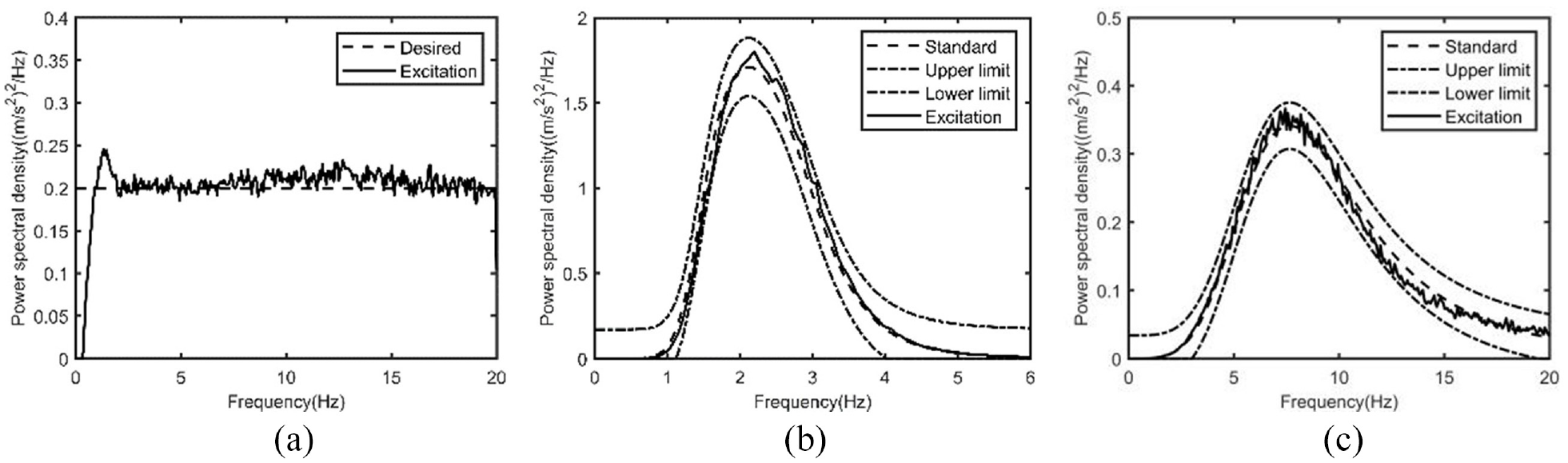
Power spectral densities for vibration excitation signals: (a) WNP, (b) EM3, and (c) EM6.
Evaluation criteria of the performance of seat suspension
According to the standardization ISO 2631-1
19
and the work of Paddan and Griffin,
20
the following indicators are chosen to evaluate the vibration isolation performance of seat suspension:


where T is the total integration time of acceleration time history;
Simulation analysis to choose the suitable damping steps of VDCS’ hard mode (“on”)
For the semi-active seat suspension with an on-off control strategy, if the damping force in the hard mode is too large, the suspension acceleration may cause a severe jerk and affect the vibration isolation performance of the seat suspension. Therefore, the vibration isolation performance of the VDCS seat suspension with different hard mode (“on”) damping values is preliminarily studied by simulation analysis to determine which step of the adjustable damper is suitable for the hard mode (“on”) damping valve of the seat suspension with VDCS. The Simulink model used in the simulation analysis is established based on equations (1)–(5) and the measured characteristic curves of each component of the seat suspension.
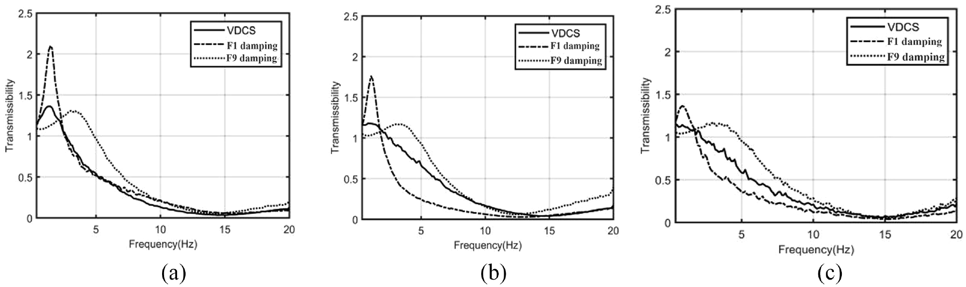
The contrastive simulation study under WNP vibration excitation mainly focuses on analyzing the acceleration transmissibility and the relative displacement of seat suspension among the different damping steps of the VDCS’ hard mode (“on”) and two fixed damping steps.( F1 damping and F9 damping). As shown in Figure 9 and

Transmissibility of different damping steps of VDCS’ hard mode and fixed damping mode.
Table 2, the results show that the higher the hard mode damping step of the VDCS is, the lower the acceleration transmissibility is below 2 Hz, and the worse the acceleration transmissibility is above 2 Hz. Since the human body is sensitive to vertical vibration in the range of 4–12 Hz, mainly in the range greater than 2 Hz, the damping step at the hard mode of the VDCS should not be too large. At the same time, if the hard mode damping step is too small, it may cause a larger relative displacement of the seat suspension. Based on the analysis results of the acceleration transmissibility and the relative displacement of seat suspension comprehensively, step 7 is a suitable choice as the damping step of the VDCS’ hard mode (“on”) in the subsequent experimental study.
Simulation results of different damping steps of VDCS’ hard mode (“on”) for WNP excitation.

Experimental test of the seat suspensions with VDCS and comparison with the case of fixed damping
Using VDCS in the seat suspension is to improve the driver’s comfort, reduce the occurrence and severity of end-stop impacts, and enhance the driver’s protection. To obtain the actual performance of the seat suspension with VDCS, the experiment is designed and performed as shown in Figure 10.
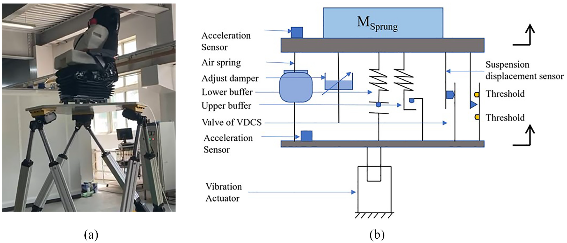
Vibration excitation experiment: (a) the physical equipment and (b) the schematic diagram.
In the test, the signals such as WNP, EM3, and EM6, are reproduced by the 6-DoF vibration platform as the vibration and shock excitation of the seat suspension. The accelerometers are installed on the upper and lower frames of the seat suspension to measure the input and output vibration acceleration. One angular sensor is arranged on the guide mechanisms of the seat suspension to measure the seat suspension’s relative displacement and the absolute position of the seat suspension’s height level. Another angular sensor mounted on the damper adjuster lever is used to measure the adjustable damper’s real-time angle of the adjuster lever to figure out the probability of the occurrence of each damping step. DASP digital acquisition equipment and data processing software are used in this experiment.
The maximum stroke of the seat suspension is 170 mm, as shown in Figure 11. The seat suspension compresses the lower or upper buffer and produces end-stop impacts when the seat suspension height is lower than 13 mm or higher than 160 mm. The driver can manually choose the appropriate height level of seat suspension from 30 to 130 mm to accommodate the different heights of the drivers. The residual suspension stroke is reserved beyond the seat suspension’s manually adjustable height level range to reduce the occurrence and severity of the end-stop impact in the seat suspension. The upper residual stroke is 40 mm (from 130 to 170 mm), and the lower residual stroke is 30 mm (from 0 to 30 mm). In order to verify the performance of the seat suspension with the VDCS, a series of experiments are carried out. Here, we select three typical suspension height levels (Level Low,30 mm, Level Medium, 80 mm, Level High, 130 mm) to set up the experiment matrix, as shown in Table 3.

Seat suspension stroke and definition of H, M, and L height level.
Experimental matrix for verifying the performance of the seat suspensions with different damping types.

As the test matrix is shown in Table 3, the performances of the seat suspensions with VDCS (the hard mode (“on”) damping step is step 7) are compared with those of the two types of fixed damping, respectively (F1 damping and F9 damping) at the same seat suspension height level and the same road excitation. These test items for comparing in the test matrix are the same seat suspension, just with the different damping types. The test matrix is designed to explain the superior performance of the semi-active control damping of VDCS compared to the soft or hard fixed damping mode (F1 damping and F9 damping) that the driver likes to choose according to the different road roughness conditions. The evaluation criteria, such as the transmissibility, the maximum relative displacement of the seat suspension, the SEAT value of r.m.s., and the SEAT value of VDV, are compared and analyzed systematically among these test items. For all the test items in the test matrix, the 75 kg dummy is used to realize the suspend mass, and the weight of the upper seat frame was 15 kg, so the total suspend mass was 90 kg.
Experimental results of the seat suspensions with different damping types under the WNP vertical vibration excitation
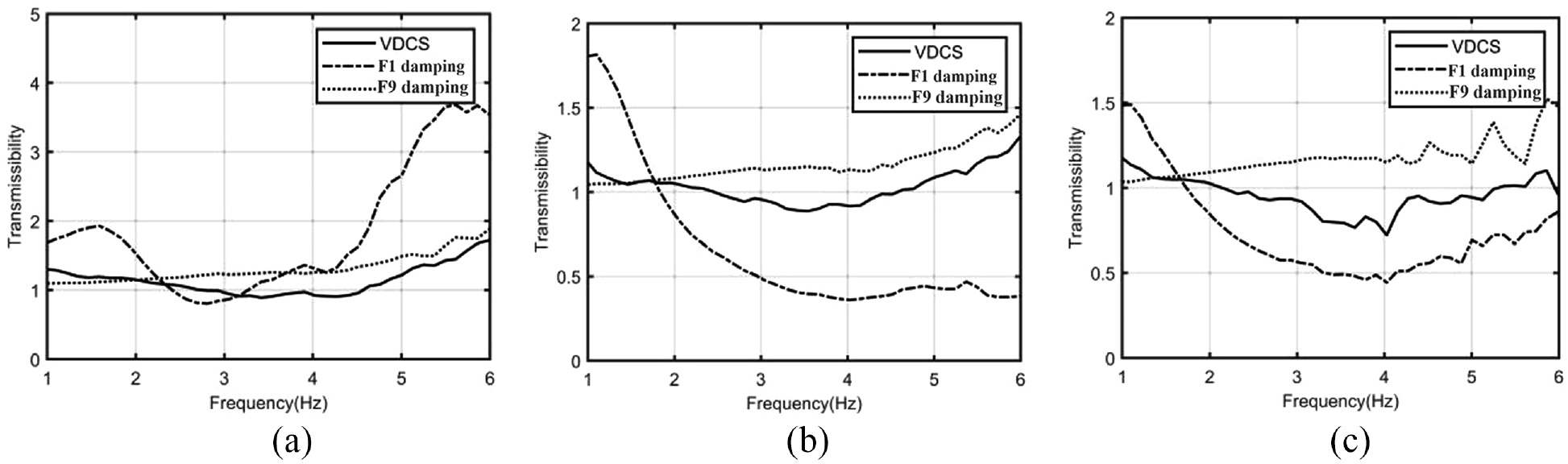
Figure 12 indicates the transmissibility of seat suspension with different suspension height levels under WNP vibration excitation and different damping modes.
Seat suspension transmissibility for different damping modes under WNP vibration excitation at the different suspension height levels: (a) L level 30 mm, (b) M level 80 mm, and (c) H level 130 mm.
We may observe that the seat suspension system with F1 damping has a resonant frequency of about 1 Hz. In the seat suspension with F1 damping, the vibration transmissibility at the resonant frequency varies significantly according to the height level of the seat. The transmissibility at the resonant frequency corresponding to low, medium, and high seat height levels are 2.10, 1.75, and 1.40, respectively.
There are two main reasons for the change of transmissibility. Firstly, with the decrease of the height, the inclination angle of the adjustable damper arrangement increases, and the equivalent damping coefficient decreases. Secondly, when the seat suspension is used at the high-level position, there is enough suspension travel to absorb the energy of vibration and impact, and the probability of the end-stop impact in the seat suspension is reduced, and the transmissibility can be reduced. At 2 Hz, the maximum transmissibility of the VDCS mode is less than 1.3, which is far less than that of F1 damping mode. Between 2 and 8 Hz, the transmissibility of VDCS mode at M and H seat suspension heights is a little higher than that relative to F1 damping mode. However, their transmissibility is basically less than 1, which doesn’t hurt comfort. At the L height level of the seat suspension, the transmissibility of VDCS mode is basically equivalent to that of F1 damping mode between 2 and 8 Hz. One reason is that, as shown in Figure 13(a), under the semi-active control of the VDCS, the adjustable damper is in Step 1 damping step for most of the whole working duration (nearly 91%). Step 1 of the damping step is just F1 damping mode, so they show nearly the same transmissibility between 2 and 8 Hz vibration excitation.
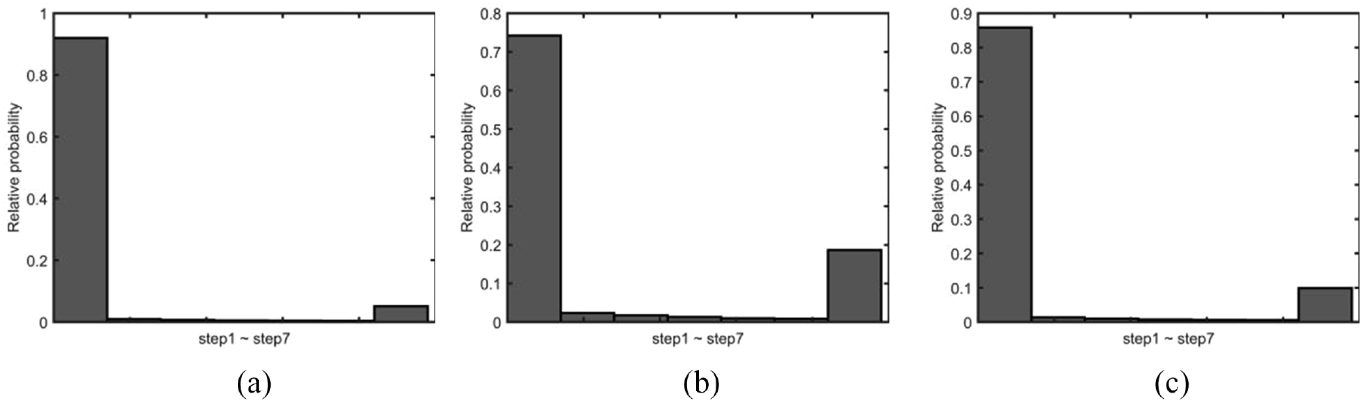
Operation percentage of different damping steps of VDCS under WNP vibration excitation at the different suspension height levels: (a) L level 30 mm, (b) M level 80 mm, and (c) H level 130 mm.
Furthermore, VDCS mode damping exhibits better vibration isolation performance at different seat suspension height levels (L M and H) than F9 damping at 2–8 Hz. These can be observed from Figure 12. At 0.4 to 2 Hz, the vibration isolation performance is similar to that of F9 damping but far better than that of F1 damping in this frequency range. To sum up, under the excitation of the WNP, VDCS damping mode has a better all-around performance than F1 and F9 damping modes.
The operation duration of the different damping of VDCS may be obtained by measuring and calculating the holding time of the adjustable damper lever at different angles during the test, as shown in Figure 13. According to the results shown in Figure 13, we may conclude that the VDCS designed in this paper is of significant on-off semi-active damping control characteristics, and the duration of soft mode (“off” step1) and hard mode (“on” step 7) reaches about 80% and 20%, respectively. Obviously, the designed VDCS excluding any electronic control system and components, can achieve the objectives of seat suspension on-off semi-active control at different suspension heights through the pneumatic control mechanism.
Experimental results of the seat suspensions with different damping types under the EM3 vertical vibration excitation
Figure 14 indicates the transmissibility of seat suspension with different suspension height levels under EM3 vibration excitation and different damping modes. We may see that the transmissibility performance of VDCS damping has a nearly 30% to 50% improvement compared with F1 damping and has similar transmissibility compared with F9 damping in the frequency range of 1–2 Hz. The transmissibility of seat suspension with VDCS damping is between one with F1 damping and one with F9 damping from 2 to 4 Hz. So we can conclude that, on the whole, the VDCS has lower transmissibility and shows better vibration isolation performance under the EM3 excitation compared to the cases with F1 and F9 damping.
Seat suspension transmissibility for different damping modes under EM3 vibration excitation at the different suspension height levels: (a) L level 30 mm, (b) M level 80 mm, and (c) H level 130 mm.
Figure 15(a) shows that the damping step of VDCS stays in Step 1 for about 80% of the whole duration under EM3 excitation duration. Moreover, the duration of damping step 7 is about 10%, and the damping step is kept in the middle of steps 2–6 for about 10%. The operation duration percentage of each step from step 2 to step 6 is similar. Obviously, VDCS drives the adjustable damper to switch on or off between these steps to achieve continuous semi-active damping control.

Operation percentage of different damper steps under EM3 vibration excitation at the different suspension height levels: (a) L level 30 mm, (b) M level 80 mm, and (c) H level 130 mm.
Figure 16 shows the relative displacements of the seat in the time domain with different damping modes at height level 30 mm and the probability of the relative displacement located in different ranges. From Figure 16, we may observe that, when the seat suspension is in L height level (30 mm), for F1 damping mode, the value of relative displacement of the seat suspension is highly scattered, and the relative displacement of suspension is at the range from less than -20mm to more than 60 mm. In this case, the end-stop impact occurs frequently, and the vibration isolation performance of the suspension system deteriorates, as shown in Figure 16(a). Actually, the seat suspension transmissibility shown in Figure 14(a) may provide further evidence.

Operation percentage of different suspension oscillation strokes under EM3 vibration excitation at L 30 mm seat height level for different damping modes: (a) damping, (b) F9 damping, and (c) VDCS damping.
In F9 damping mode (Figure 16(b)), the relative displacement of suspension is concentrated near the equilibrium position, and more than 90% of the relative suspension displacement is within ±10mm. We may also see that, although the relative displacement of the seat suspension system is small in F9 damping mode, the vibration acceleration increases and the comfort decreases.
However, for the VDCS damping mode (Figure 16(c)), the maximum relative displacement is reduced to less than 30 mm, and more than 60% of the seat suspension relative displacement is within ±10mm. According to the results of Figures 14 and 16, we may conclude that the VDCS damping system can effectively reduce the relative displacement of the seat suspension system while maintaining lower transmissibility.
Experimental results of the seat suspensions with different damping types under the EM6 vertical vibration excitation
The primary and dominant frequencies (2–20 Hz and 7.6 Hz) of EM6 vibration excitation are much higher than the seat suspension system’s resonant frequency (about 1.3 Hz). The vibration amplitude of the seat suspension system caused by EM6 vibration excitation is too small to cause the travel of seat suspension to exceed the displacement threshold. So the VDCS cannot reach the damping mode shift position, and the adjustable damper remains in soft mode (“off”). Therefore, the vibration isolation performance of the seat suspension system in VDCS mode damping is precisely the same as that in soft mode (“off”), as shown in Figure 17, and the end-stop impact of the seat suspension system does not take place throughout the whole test. Under the EM6 vibration excitation, the best damping mode for the seat suspension is the soft mode (“off”). Therefore, these results also fully reflect that the seat suspension equipped with VDCS can select the most appropriate damping mode according to the road excitation input and achieve the effect of semi-active damping control automatically.

Seat suspension transmissibility for different damping modes under EM6 vibration excitation at the different suspension height levels: (a) L level 30 mm, (b) M level 80 mm, and (c) H level 130 mm.
Comparisons of experimental results of the seat suspension under the different vertical vibration excitations
To summarize the vibration isolation performance of seat suspension with VDCS more clearly, according to the test items listed in the test matrix (Table 3), the detailed comparisons of seat performance are conducted and shown in Tables 4 to 6.
Measured SEAT factor (r.m.s. and VDV) and maximum relative displacement under WNP excitation.

Measured SEAT factor (r.m.s. and VDV) and maximum relative displacement under EM3 excitation.

Measured SEAT factor (r.m.s. and VDV) and maximum relative displacement under EM6 excitation.

In these tables, the evaluating criteria, such as SEATr.m.s., SEATVDV, and the maximum displacement, are utilized to study the performance of the seat suspension with different modes of damping under vibration excitation WNP, EM3, and EM6, respectively. Sum. is the sum of the values of each evaluation criteria at different seat suspension heights(Level L, M, and H ). Sum Variation (%) (S.V.%) is the percentage change of each evaluation criteria’s sum of the fixed damping(F1 or F9) relative to that of the VDCS damping. Sum and S.V.% are also selected as a comprehensive evaluation index to evaluate the performance of the seat.
From Table 4, we may observe that, the sum of the SEAT r.m.s and the SEATVDV of F1 damping slightly decreases by 15.7% and 7.8% relative to the sum of the VDCS damping, respectively. However, the maximum relative displacement significantly increases, and the corresponding sum valve variation of the maximum relative displacement is nearly 61.9%. Therefore, for the F1 damping mode, there exist risks in safely controlling the vehicle for the driver and increasing the chance of end-stop impact. The sum of the SEAT r.m.s and the SEATVDV of F9 damping remarkably increases by 38.6% and 28.4% relative to the sum of the VDCS damping, respectively. As a result, the comfort performance of the seat suspension is significantly reduced. The maximum relative displacement only declines from about 30 mm to about 20 mm, and it may have little effect on the performance of the seat suspension. In conclusion, under WNP vibration excitation, the comprehensive performance of VDCS damping is better than that of the fixed damping (F1 damping and F9 damping).
From Table 5, we may see that, the S.V.% valve of the SEAT r.m.s and the SEATVDV of F1 damping are 6.8% and 2.4%, respectively. Based on the S.V.% valve mentioned above, the seat suspension’s comfort performance of VDCS damping and F1 damping is nearly the same. Nevertheless, the maximum relative displacement of F1 damping is about 50 mm, nearly 20 mm larger than that of VDCS damping (Around 30 mm). Under the EM3 vibration excitation, the more significant displacement may increase the occurrence and severity of the end-stop impact. The sum of the SEAT r.m.s and the SEATVDV of F9 damping slightly increases by 16.9% and 8.2% relative to the sum of the VDCS damping, respectively. The maximum relative displacement only declines about 10 mm, and it may have little effect on the performance of the seat suspension. To sum up, under EM3 vibration excitation, the comprehensive performance of VDCS damping is better than that of the fixed damping (F1 damping and F9 damping).
From Table 6, we may see that, under EM6 vibration excitation, the stroke of the seat suspension system with VDCS damping does not exceed the displacement threshold of 18 mm, and the adjustable damper of the seat suspension is always in soft mode damping. The SEAT r.m.s., SEATVDV, and maximum relative displacement of the seat suspension with VDCS damping are the same as that of the F1 damping. With EM6 vibration input, there is no occurrence of the end-stop impact. Therefore, the VDCS damping provides better vibration isolation performance for the seat suspension.
Conclusions
The design of the seat suspension system needs to meet several contradictory design objectives. Although the traditional semi-active seat suspension can better meet these design objectives to a certain degree, the complex electronic control system has become an obstacle to its wider application. In this research, one of the findings is that the newly designed pneumatic mechanism system (VDCS) excluding electronic components can simplify the structure and realize the function of the on-off semi-active control in the seat suspension.
Based on the research results, under the excitation of WNP, EM3, and EM6, the VDCS damping control system has a better all-around performance than the traditional passive damping system with the fixed F1damping and the fixed F9 damping modes. Overall, the VDCS on-off semi-active control system has a broad application space due to its simple structure and excellent performance.
Furthermore, the pneumatic control valve of VDCS can be used as a sensor, and the pneumatic driving cylinder and the adjustable damper act as an actuator. This design concept of using pneumatic components to realize the functions of the electronic control components in traditional semi-active systems provides a new idea for designing the semi-active control system. In the future, VDCS may also be used in the semi-active control of the chassis and cabin suspension system of the vehicle.
At the same time, the VDCS has the advantage of lower cost, lower complexity, and general equivalence performance with the on-off control strategy of the electronic semi-active damping control system. Therefore, the VDCS seat suspension is an excellent compromise solution among traditional passive, semi-active, and active seat suspensions.
Footnotes
Acknowledgements
We thank the seat OEM supplier, GoldRare automobile parts Co., Ltd, China, for supplying the Daimler Truck new project seat in the experimental research.
Handling Editor: Chenhui Liang
Declaration of conflicting interests
The author(s) declared no potential conflicts of interest with respect to the research, authorship, and/or publication of this article.
Funding
The author(s) received no financial support for the research, authorship, and/or publication of this article.