
Abstract
The present study examines the effect of the thickness, cutouts numbers, and different cutouts shapes on the ratcheting behavior of 304 steel sheets under cyclic axial loading. The cutout shapes considered here are circular, triangular, and square cutouts. The effect of the number of circular cutouts in 304 steel sheets on ratcheting behavior is investigated. The Instron 8502 device is used to perform the experiments in which the cyclic axial loading is applied to six specimens with different cutouts and thicknesses at ambient temperature. The obtained results highlight the fact that reducing the thickness and increasing the number of cutouts in the sheets are attributed to the rise in the ratcheting displacement. Accordingly, the ratcheting displacement is more striking in the sheets with triangular cutouts. Notably, a numerical analysis is considered using the isotropic/kinematic nonlinear hardening model and FEM in ABAQUS software. Since a good agreement is seen between the numerical and experimental results, the analysis conducted in this study is reliable in terms of accuracy and authenticity.
Introduction
Due to the recent development in mechanical and civil engineering, the structures and mechanical components are significantly exposed to randomly variable loads nowadays.1–4 On the other hand, the engineering structures like pressure vessels, piping systems, and offshore structures are constantly subjected to cyclic axial loading or cyclic thermal loading. The stress cycles’ values applied to the structures are sometimes more than their yield strength and bring unwanted damages.5–8 These stress cycles, along with the mean stress, create remarkable accumulations of plastic deformation, namely ratcheting, and finally lead to the failure phenomenon. 9 However, the previous decades have witnessed a growing interest in the study of ratcheting behavior in the material; there is still considerable ambiguity regarding this topic because it is a secondary plastic deformation process and progressively occurs cycle by cycle.10–12 Thus, the study in this field is of great importance in predicting the materials’ lifetime under characteristic cyclic loading.
The study of ratcheting dates back many years ago,13–18 but it is still a challenging issue that needs to be studied in depth. The number of cycles that lead to ratcheting can be significantly effective in terms of intensification and amount of ratcheting strain. In 2003, Chen et al. 19 aimed to simulate the ratcheting strain considering a high number of cycles subjected to biaxial loadings. This study has considered a corrected form of the Ohno–Wang kinematic hardening rule to reach more accurate numerical results. The question here arises of what factors are effective in ratcheting behavior to what extent. In 2004, Weiß et al. 20 ratcheting was introduced as a secondary phenomenon of cyclic plasticity that intensifies fatigue damage. Also, deformation behaviors and microstructure evolution of a hot-rolled AZ31B magnesium alloy were examined by Wang et al. 18 After that, in 2021, Chen et al. 21 studied the issue of cyclic lithium-ion diffusion-induced stress within the charging-discharging process. In this study, the plastic behavior of lithium-ion battery cathode has been systematically examined, and the effect of the cycle number has been analyzed. These studies mainly investigated the effect of cycle number on ratcheting behavior and did not address the effect of shape dimensions. Notably, the geometrical dimensions and material are also important to reach reliable results.
A large number of existing studies in the broader literature have examined the ratcheting phenomenon for various materials.22–28 Besides, the different geometries have been investigated to analyze the obtained results so far, among which the cylindrical specimens have been widely employed.29,30 For instance, Kobayashi and Ohno 31 examined the ratcheting behavior for the SS304 cylindrical shells and presented valuable results. Lee et al. 32 also conducted an identical study for the cylindrical shells of SS316 in 2003. Hamidinejad and Varvani-Farahani 33 conducted an experimental study for 1045 and 1Cr18Ni9Ti steel in 2015. Shariati et al. investigated the ratcheting behavior of cantilever specimens of SS316L steel cylindrical shells under cyclic bending loads. The authors indicated that plastic deformation accumulates in the specimen after each cycle, and as the cycles increase, the diagram loops become closer. 34 Shariati et al. 35 also conducted a numerical study in 2011 concerning the investigation of ratcheting in cylindrical shells. The authors investigated the effect of frequency and thickness on ratcheting behavior and fatigue life of polystyrene pipe under cyclic axial loading. Zhu 9 investigated the effect of increasing force amplitude on the ratcheting behavior of cylindrical shells produced of CK20 steel under cyclic loading, and accumulation of ratcheting strain increases with increasing stress amplitude at constant average stress. It was also revealed that the increased average stress could also be one of the factors affecting this behavior. Shariati et al. 36 investigated the effect of this factor on SS316L steel and concluded that in the constant amplitude of force, with increasing average force, the displacement accumulates, and its rate increases. Also, in another study in this regard, the author did some experiments on cylindrical shells with different lengths under combined and cyclic axial loading. 37 According to the results obtained in this study, a rise in the length of cylindrical shells due to increasing flexural torque and increasing vertical stresses at different sections of oblique cylindrical shells with longer lengths leads to increasing ratcheting displacement. One of the significant factors that have an essential factor on the ratcheting behavior of the cylindrical sells is the diameter investigated by Shariati et al. 38 in 2016. In this study, the effect of this factor was experimented with by considering two samples of cylindrical shells produced of SS304L steel with different diameters and under cyclic pure bending loading. The effect of cutout shape on the ratcheting angle on torsional loading on cylindrical shells has also been studied by Shariati et al. 34 According to this research, the cylindrical shells of SS316L with circular, square, and triangular cutouts were subjected to cyclic torsional loading, and the ratcheting angle diagram was obtained based on the number of loading cycles.
One of the industry’s most functional components is a pipe that transfers liquid, gas, slurries, and other solids and fluids from one area. Since these components are sometimes subjected to severe cyclic loadings, the study in this regard is also important. Concerning the ratcheting phenomenon in the pipes under cyclic loadings,39,40 Zeinoddini et al. 6 considered the ratcheting behavior in the low-alloy, high-strength steel pipes (API-5L X80) subjected to cyclic bending. Additionally, Zakavi et al. 41 assessed the combined stiffness model in the elbow ratcheting behavior of pressurized pipe under in-plane torque. The ratcheting phenomenon for the elbow under pressurized bending after thermal aging was investigated experimentally and numerically by Liu et al. 42 in 2019. In another study, the uniaxial and biaxial ratcheting behavior of pressurized AISI 316L pipe under cyclic loading was examined by Moslemi et al. 43 and presented acceptable results. In addition, Kang 23 and Karimi and Shariati 44 studied experimental and numerical analysis of the ratcheting behavior of SS316L thin-walled pipes under cyclic internal pressure. There exists a considerable body of literature on ratcheting behavior in other geometries. The previous studies aimed to examine the effect of this phenomenon in a variety of geometries like pipes,45,46 circular components,17,47 axial pipes, 48 sheets,49–51 and so on. To mention a few, Kolasangiani et al. 52 studied the ratcheting behavior of plates with a circular cutout under axial cyclic loading. The ratcheting behavior of notched steel samples subjected to asymmetric loading cycles through coupled kinematic hardening-Neuber rules was also examined. 53 The authors also investigated the ratcheting progress at the notch root of 1045 steel samples over asymmetric loading cycles. 54 Chen et al. 55 also analyzed the effect of circular holes on the ratchet limit and cracked tip plastic strain range in a center cracked plate. Dong et al. 56 examined the low cycle fatigue and ratcheting failure behavior of AH32 steel under uniaxial cyclic loading. Luo et al. 57 conducted an experimental study on the heterogeneous ratcheting behavior of SUS301L stainless steel butt weld joint during uniaxial cyclic loading. An experimental study was conducted on the uniaxial ratcheting-fatigue interaction of polyamide-6 by Yang et al. 58 Further, Weiß et al. 20 and Liu et al. 59 investigated ratcheting-fatigue behavior and damage mechanism of GH4169 at 650°C. The ratcheting fatigue behavior of 42CrMo4 steel under different heat treatment conditions was also examined by Kreethi et al. 60 in 2017. One of the most important components in engineering is sheet metal due to its remarkable capabilities in modern buildings, manufacturing, and construction sectors. In fact, sheet metal is widely employed in various industries such as car manufacturing, aircraft parts, tools, agriculture, mining, catering, shipping, medicine, and electronics. Thus, most early studies, as well as current work, focus on the ratcheting behavior of the steel sheets,50,61–63 Z2CND18.12 steel sheets, 64 and molybdenum sheets. 65 For example, De et al. 66 experimentally studied the ratcheting phenomenon on steel sheets in 2017. Concerning the results obtained in this study, the plastic strain accumulation rate turned out to be high in the initial cycles and decreased in the subsequent cycles. Shahrjerdi et al. 67 obtained the Bree diagram to specify the ratcheting and non-ratcheting areas for a functionally graded beam under cyclic thermal and axial loading. In light of recent events in the ratcheting phenomenon for the various material and geometries, there is now some considerable concern about the influential factors affecting the intensification of this behavior.
The majority of studies mentioned above emphasize the effects of dimensions and cycle number of loading on the amount of ratcheting strain and the corresponding results. Besides, the importance of study in the field of sheet ratcheting has been clarified. Despite such interest, we have yet to study the effect of sheets’ thickness on ratcheting the factors affecting this behavior to the best of our knowledge. Considering the widespread use of 304 steel sheets with different thicknesses in the industry, it is important to study their ratcheting behavior considering the effect of thickness. On the other hand, examining the effect of the shape and number of cutouts on sheet ratcheting is essential because cutouts with different shapes are sometimes created in the sheets for many purposes. A more detailed look at the literature reveals a number of gaps and shortcomings, which are as follows. As a novelty, the effect of shape, cutout number, thickness, and dimension on 304 steel sheets are simultaneously discussed in the current paper. Also, the numerical simulation and experiments regarding the ratcheting behavior of 304 steel sheets are examined under cyclic axial loading with various cutouts and dimensions.
The rest of this study is organized as follows: Section 2 outlines the methods and material considered to conduct the experiment and validate the results. The information regarding the ratcheting concept and the issue of hardening and softening is presented in the third section. The fourth section analyzes and discusses the results obtained for the sheet specimens under cyclic axial loading. In addition, a careful comparison is made between the numerical and experimental results in the fifth section to prove the authenticity and accuracy of the analysis conducted in this research. The main conclusions obtained from the experiments and numerical analysis, as well as the suggestions for future study, are drawn in the sixth section.
Preliminaries
Since nowadays many structures are under cyclic external forces which lead to fracture, the issue of ratcheting is very important. These cyclic loads gradually increase the probability of failure due to the creation of more strains by small values per cycle. This type of loading is called cyclic plasticity or elasticity, a low-cycle fatigue type. However, to observe the sample’s ratcheting phenomenon, the load needs to be in the form of control stress, and the amount of stress amplitude must be beyond its elastic domain. 68 In general, the following conditions need to be applied to examine the ratcheting behavior in the sample:
The sample is subjected to cyclic loading.
Plastic deformation occurs in each cycle.
The mean stress is non-zero.
The plastic strain (average of each cycle) increases when the cycle rises. One of the significant effects of the ratcheting phenomenon on a component is that the crack growth is observed earlier, and failure occurs earlier in the ratcheting zone. For this reason, in designing parts and industrial structures, it is essential to evaluate the ratcheting phenomenon as an important and effective factor for the failure phenomenon. 25
In general, three types of ratcheting can be observed in material behavior. Accordingly, the first type is related to the mitigation of the ratcheting rate, which causes elastic/plastic shakedown. This result is mainly obtained when the material is highly cyclic hardening. The second type is related to the condition in which the strain rate is constant, which leads to the accumulation of plastic strains in the material. The third type of ratcheting is associated with a rise in strain rate. Such conditions are presented in Figure 1 to understand their effects entirely.

The schematic of various types of ratcheting.
Methodology and material
Overall, the present study consists of the experimental and numerical analyses considered for the samples of steel sheet 304. In this section, these methods are explained in detail, and the mechanical properties of SS304 based on ASTM E8 are highlighted in Table 1. Also, Table 2 shows the chemical properties of SS304 used in this study.
The mechanical properties of SS304.

The chemical properties of SS304.

Figure 2 gives the necessary information regarding the process of the analyses conducted in this study. In order to thoroughly understand the steps that need to be taken in this study, devoting attention to this figure is of great importance.

The steps need to be taken to reach the final conclusion.
The experimental method
The experimental analysis is conducted through the Instron 8502 device that is able to apply dynamic loads up to 250 kN, and the main experiments are performed on six samples of SS304. The samples are subjected to cyclic axial loading, and the force-displacement diagram of each sample up to 200 cycles is extracted and examined. The experiment investigates the effect of sheet thickness, shape, and number of cutouts on the rectangular specimens prepared for the experiment. The specimens considered in the experiments are 100 mm long, and their width is 50 mm. In order to examine the effect of sheet thickness on the ratcheting behavior, the samples with thicknesses of 0.93 and 1.93 mm and a circular cutout in the center of the samples are employed. Also, the samples with a thickness of 0.93 mm are considered to examine the effect of the cutouts on the ratcheting behavior. One, two, and four circular cutouts with a diameter of 8 mm are created. It should be noted that there is an equal distance between the cutouts existing in the center of the samples. Since the effect of the cutout shape on the ratcheting behavior is considerable, the SS304 sheet samples with circular, square, and triangular (equilateral) cutouts and the same area (about 50 mm2) are examined in the center of the samples. According to the prepared samples shown in Figures 3 and 4, the diameter of the circular cutout is 8 mm, and the lengths of the square and triangular cutouts are 7.09 and 10.75 mm, respectively. One specimen was tested for each case. However, two or three samples were tested before the primary analysis to reach a suitable loading.
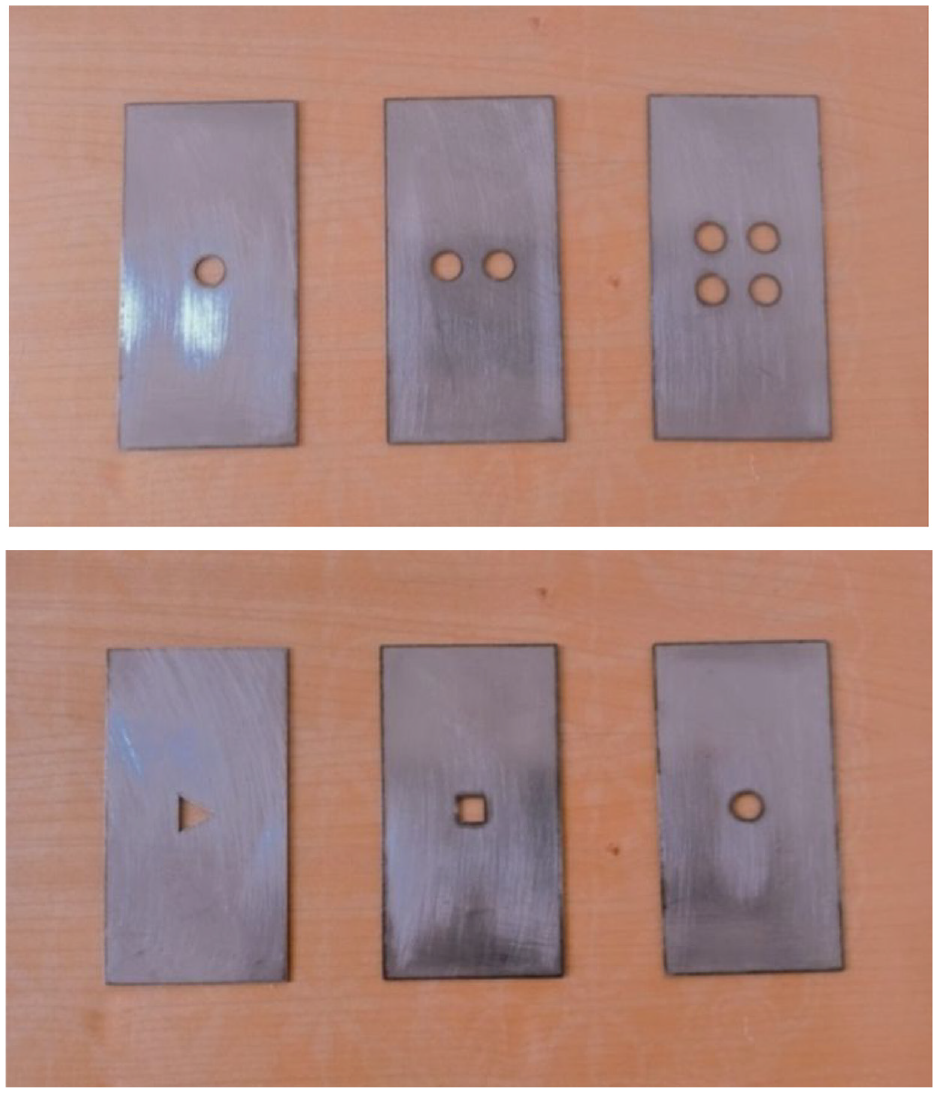
The circular, triangle, and rectangular specimens.

Sample P1 under loading condition.
Furthermore, these samples’ geometric and loading specifications are reported in Table 3. Since the loading is force-control and the ratcheting phenomenon of SS304 is considered in this study, the applied force needs to result in ratcheting behavior and simultaneously prevent failing the specimens in the initial cycles. The stress-strain curve obtained by the standard tensile test is illustrated in Figure 4.
The loading and geometric characteristics of the SS304 sheet samples.

The simple tensile test is uniaxial according to which

For plane stress, the von Mises stress can be represented by equation (2) 69 :

In the beginning, some specimens were considered for the tensile test and stability to specify the same range of load for applying the whole specimens. In fact, their capability to bring ratcheting results without failure in the primary cycles is guaranteed in this test. As seen from Table 3, according to the tensile and stability tests, the average force of 6550 N and amplitude of 5750 N were suitable for applying to the specimens periodically (sinusoidal) with a frequency of 0.2. This average and amplitude produce a maximum force of 12,300 N and a minimum force of 800 N. In this study, the highest sheet displacement in each cycle is considered ratcheting. Figure 4 outlines one of these specimens subjected to the average load.
The numerical method
In order to prove the reliability and authenticity of the results obtained in this study, the simulation method is also considered to make a careful comparison between the numerical and experimental analyses. For the simulation, the finite element method is employed using ABAQUS software and considering a combination of isotropic and kinematic hardening methods. In general, three types of isotropic, kinematic, and combined hardening are defined in the simulation. Isotropic hardening means that the level of yield changes equally in all directions. When the plastic stress appears in all directions, the yield surface decreases or increases equally. Nevertheless, the yield surface in kinematic hardening is transferred in the stress space and does not change size. This displacement moves in proportion to the back stress in the yield space, but it does not deform. Combining two isotropic and kinematic hardening methods, that is, isotropic/kinematic nonlinear hardening, the material’s behavior can be modeled accurately under cyclic loading. This model is a combination of two isotropic and kinematic hardening, in which the yield surface is transferred by kinematic hardening, and the yield surface size is changed by isotropic hardening. Using this model, phenomena such as ratcheting can be modeled.
This model is based on the equation provided by Chaboche, which is shown below. According to this equation, the movement of the yield surface is proportional to the value of

Where
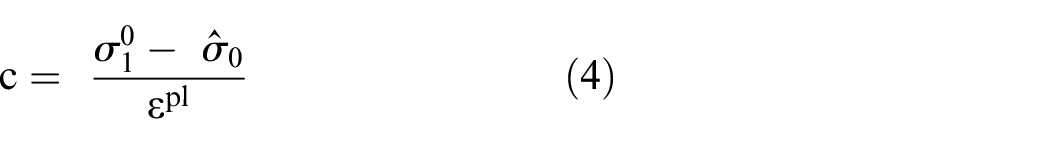
Where

According to equation (5),
Results and discussion
This section outlines the results obtained by applying the average force to the specimens and considering the force amplitude (N) and other geometric conditions illustrated in Table 3.
The effect of thickness on ratcheting caused by cyclic axial loading
Figure 5 indicates the force-displacement diagram in 200 load cycles for Samples P1 and P2. As shown in both diagrams, after each cycle, the loops of the diagram move, and the plastic strain starts accumulating. Notably, the distance between the diagram loops becomes slighter as the cycles increase. Hence, a remarkable reduction in the ratcheting displacement rate in the higher cycles is observed.

Force-displacement diagram of the Sample: (a) P1 and (b) P2.
Figure 6 shows the ratcheting displacement diagram versus the number of cycles for Samples P1 and P2. According to the sheet thicknesses, as the number of cycles increases, the ratcheting displacement rate accumulated in the sheet decreases. This result is more accurately illustrated in Figure 6(b), where the ratcheting displacement diagram versus the number of cycles up to 30 based on the applied force is shown. The diagram slope reaches zero after a characteristic cycle, and the accumulated ratcheting displacement is saturated. Accordingly, the increase of the ratcheting displacement almost stops from the 30th cycle onward and tends to become zero since the plastic deformation accumulation stops and the regular and stable formation of dislocations after a certain number of cycles, which depends on the applied load and the material and geometric conditions of the samples appear. Also, the increase in the sheet thickness reduces the ratcheting displacement, which is due to increasing the cross-section area and thus reducing the stress created in the sheet. Notably, increasing the sheet thickness up to two times in size leads to decreasing the accumulated ratcheting displacement by 14.47%. The reason for the reduction of the ratcheting displacement rate to zero and the cessation of the accumulation of plastic deformation is the regular and stable dislocations after a certain number of cycles, which depends on the applied loading, the material, and the geometric conditions of the sheets. The increase in thickness increases the cross-section, and subsequently, the stress reduces. Hence, the strain values created in the thick areas are insignificant. Notably, the ultimate strength of the specimen increases with the elevation of thickness, that leads to reducing the strain.

Ratcheting displacement diagram versus the number of cycles of Samples P1 and P2 in (a) 200 cycles and (b) 30 cycles.
The effect of circular cutouts on the ratcheting behavior caused by cyclic axial loading
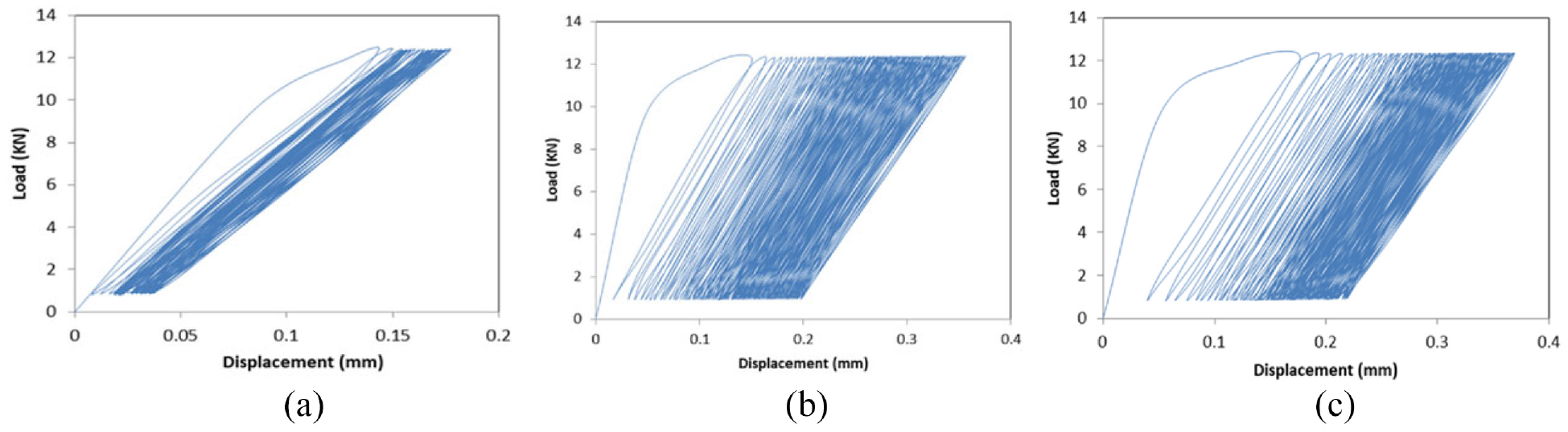
Three samples, namely P1, P3, and P4, were subjected to cyclic loading considering the control force with an average force of 6550 N and a force amplitude of 5750 N. Then, the effect of the number of cutouts on the ratcheting behavior of 304 steel sheets was examined. Figure 7(a)–(c) highlight the force-displacement diagrams of Samples P1, P3, and P4, respectively.

Force-displacement diagram of Samples: (a) P1, (b) P3, and (c) P4.
Regarding Figure 7(a)–(c), the number of cycles directly relates to the ratcheting displacement, and the diagram loops move forward with increasing the cycles. Also, the diagram loops become closer to each other, indicating a decrease in the rate of ratcheting displacement accumulation. The same findings were obtained in the study of Shariati and Hatami 71 in 2012. In the research, the authors indicated that the rate of ratcheting rises with the higher force amplitude. The authors concluded that the cutout effect causes softening and ratcheting behaviors in a cylindrical shell.
Figure 8(a) and (b) show the three hysteresis loops of the force-displacement diagram of the P3 and P4 samples, respectively. The initial loop is related to the first cycle of the diagram, the second loop is related to the 80th cycle of the diagram, and the final loop is related to the 160th cycle force-displacement diagram. Clearly, the rate of displacement accumulation reduces after a while. It can be seen that from the first cycle to the 80th cycle, the ratcheting displacement accumulation in the sample is significantly greater than the ratcheting displacement existing from the 80th to the 160th cycle.
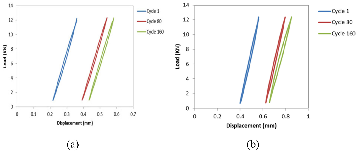
Hysteresis loops of the force-displacement diagram of: (a) Sample P3 and (b) P4.
The ratcheting displacement diagram versus the number of cycles for Samples P1, P3, and P4 are shown in Figure 9. According to the diagrams of all three samples, it is clear that as the number of cycles increases, the ratcheting displacement increases. Also, the ratcheting displacement rate in Sample P1, which has a circular cutout, decreases to zero from cycle 30 onward. This could also be observed in the force-displacement diagrams of all three samples. In contrast, the ratcheting displacement rate does not reach zero for the other two sheets, and the accumulation process continues until the ratcheting displacement rate in Sample 4 increases from the 150 cycle onward. The main reason for this increase in sheets P3 and P4 compared to sheet P1 is the presence of more cutouts and the stress concentration in these areas, which leads to creating dislocations and small cracks around them. It should be noted that by increasing the cutouts from a circular cutout to two circular cutouts whose diameters are 8 mm and are the same, the ratcheting displacement increases about 180% – also, increasing two circular cutouts up to four circular cutouts with an 8 mm diameter results in a 49% increase in ratcheting displacement. The ratcheting in the sheets causes micro-cracks in the holes, eventually leading to a failure by increasing the intensification of ratcheting over time. As mentioned by Chen et al. 55 in 2011, the growth of cracks in the manufacturing of the structures affects the load capacity, residual strength, life, and integrity of the structures. The local stresses increase with the rise in the hole area, leading to increased ratcheting displacements and strains. The local stresses depend on the stress concentration factor and the stresses created in the cut cross-section. However, the stress concentration factor is reduced by the increase of the hole diameters, and the stresses in this area increase due to the reduction of the cross-section that brings more accumulation of plastic strains.

Ratcheting displacement diagram versus the number of cycles for Samples P1, P3, and P4.
Furthermore, as regards Figures 7(b) and 8(a), the range of ratcheting displacement variations for the minimum force with the value of 0.2166 starts from the first cycle and continues to 0.4333 in 160 cycles, based on which the total of displacement accumulation is 0.2167. This displacement starts from 0.36041 in the first cycle and continues to 0.5833 in 160 cycles according to the maximum force. Notably, the total displacement accumulation is 0.2229. According to such difference, the accumulation created for the minimum and maximum forces shows that the slope of the hysteresis loops in Sample P3 is decreasing, and the softening behavior occurs in the sample. The results of Figures 7(c) and 8(b) highlight that the ratcheting displacement variations for the minimum force are 0.3998, which starts from the first cycle and continues up to 0.6581 within 160 cycles. In total, the accumulated displacement is 0.2583. The maximum value of displacement force for the first cycle starts from 0.5623 and continues until 0.8519 in 160 cycles. In this case, the displacement force is 0.2896 in total. This difference is based on the maximum and minimum forces, and the slope of the hysteresis loops in Sample P4 is decreasing, which leads to softening behavior in the sample.
The effect of cutout shape on the ratcheting behavior under cyclic axial loading
In order to examine the effect of cutout shape on the ratcheting behavior, a cyclic load with an average force of 6550 and a force amplitude of 5750 was applied to Samples P1, P5, and P6 as a controlled force. Due to the similarity of the other conditions in the three samples, a comparison can be made between the effect of three circular, triangular, and square cutouts with the same area on the sheet ratcheting behavior. Figure 10(a)–(c) indicate Samples P1, P5, and P6’s force-displacement diagrams. As can be concluded from the diagrams, the number of cycles is in direct proportion to the ratcheting displacement in terms of quantity. Hence, a rise in the cycles constitutes the proliferation in the ratcheting displacement. Notably, at the higher cycles, the loops approach each other further and further so that a decline in the ratcheting displacement rate is observed in this condition.
Force-displacement diagram of Sample: (a) P1, (b) P5, and (c) P6.
According to Figure 10(b) and (c), the ratcheting displacement variations for the minimum force is 0.0312, which starts from the first cycle and continues up to 0.1770 within 160 cycles. Notably, the accumulated displacement is 0.1458 in total. The maximum value of displacement force for the first cycle is 0.1645 in the beginning and continues up to 0.3270 in 160 cycles. In this situation, the total displacement force is 0.1625. This difference is illustrated according to the maximum and minimum forces, and the slope of the hysteresis loops in Sample P5 decreases, which leads to softening behavior in the sample. The analysis of this research bears a close resemblance to the one conducted by Kolasangiani and Shariati. 72 This study examined the cutout effects on cylindrical shells exposed to cyclic loadings, raising the plastic deformation and its rate.
Figure 11(a) and (b) correspond to square and triangular diagrams; respectively, a decrease in the ratcheting displacement rate can be seen. It is clear that in both samples, the accumulated ratcheting displacement in the sample from cycles 1 to 80 is much higher than the accumulated ratcheting displacement from cycles 80 to 160. Overall, in the higher cycles, the hysteresis loops get closer to each other since the ratcheting dislocations form stably, and the plastic deformation accumulation decreases in higher cycles.

Hysteresis loops of the force-displacement diagram of Sample: (a) P5 and (b) P6.
According to Figure 11(a) and (b), the ratcheting displacement rate rapidly approaches zero, and the accumulation of the ratcheting displacement stops in Sample P1, which has a circular cutout. In samples with square and triangular cutouts, the increase in cycles leads to decrement the ratcheting displacement rate in the beginning. Then, this trend continues until the slope becomes stable, and subsequently, the ratcheting displacement increases in Samples P5 and P6, with the increasing number of cycles.
As regards Figure 12, the ratcheting displacement of Sample P6 in each cycle is generally greater than those of the rest. Accordingly, the ratcheting displacement of Sample P5 is greater than Sample P1 due to the presence of triangular and square cutouts in these samples and plastic deformations caused by sharp roots in these cutouts, which leads to creating and propagating the cracks around them. Since the stress concentration is more remarkable in the triangular cutouts, the deformation in Sample P6 is considerably more than in Samples P1 and P5. Concerning the presence of four sharp roots in Sample P5, the ratcheting displacement rate of this sample is higher than in Sample P6, where the diagram slope is stable. It should be noted that the accumulated ratcheting displacement in the initial cycles for the specimens with rectangular and triangular cutouts is 38% and 63% more than the specimen with circular cutouts.

Ratcheting displacement diagram versus the number of cycles for Samples P1, P5, and P6.
According to Figures 10(c) and 11(b), the ratcheting displacement variations for the minimum force is 0.0562, which starts from the first cycle and continues up to 0.2 during 160 cycles. It is noteworthy that the accumulated displacement is a total of 0.1438. The maximum value of displacement force for the first cycle is 0.1937 at first and reaches 0.3479 within 160 cycles. Accordingly, the displacement force is 0.1542 in total. This difference is obtained based on the maximum and minimum forces, and the slope of the hysteresis loops in Sample P6 decreases, leading to softening behavior in the sample.
Validation
In this section, a careful comparison is made between the numerical and experimental results of Samples P1–P6 to prove the reliability of the analysis conducted here in terms of accuracy and authenticity. Numerical and experimental Force-displacement diagrams and numerical and experimental ratcheting displacement diagrams are also compared. As stated earlier, the FEM method and ABAQUS software were used. The specimens were considered based on the boundary conditions and loading applied to the specimens to simulate the experiments in ABAQUS software. Figure 13 indicates the meshed structure of the specimen in which the CPS4R element, a quadrilateral element with plane stress, is employed. No code has been used for simulation. The specimens were designed in the beginning using the plain stress condition. The mechanical properties of SS304 were applied to the simulation processes. Then, the coefficients of the hardening techniques were inserted into the software. The analysis was conducted based on the whole conditions of the experiments. The equations presented in the manuscript are essential to present the theoretical information of the study. Also, the properties of SS304 and the parameters of the hardening behavior are determined in the software.

The meshed structure of Sample P5 in ABAQUS.
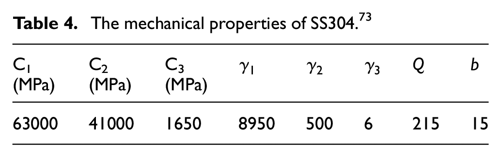
The isotropic/kinematic hardening parameters employed in Abaqus software are characterized in Table 4.
The mechanical properties of SS304. 73
The comparison between the FEM results and the experimental results of Samples P1–P6 based on the ratcheting displacement and number of cycles is illustrated in Figures 14–19.

Numerical and experimental diagram of ratcheting displacement based on the number of cycles for Sample P1.

Numerical and experimental diagram of ratcheting displacement based on the number of cycles for Sample P2.

Numerical and experimental diagram of ratcheting displacement based on the number of cycles for Sample P3.

Numerical and experimental diagram of ratcheting displacement based on the number of cycles for Sample P4.

Numerical and experimental diagram of ratcheting displacement based on the number of cycles for Sample P5.

Numerical and experimental diagram of ratcheting displacement based on the number of cycles for Sample P6.
Figure 14 shows the numerical and experimental results of Sample P1 under loading with an average force of 6550 N and an amplitude of 5750 N. There is a good agreement between the numerical and experimental results, and the comparison results represent the unique capability of the isotropic/kinematic nonlinear hardening model to simulate the ratcheting behavior of the sample. The FEM method and Abaqus software results show more ratcheting displacement based on cycles. Notably, the error of the numerical results based on the experimental ones is 15%. In Sample P2, the error of numerical results is higher than the experimental results. By increasing the thickness of the sample, the numerical results in simulating the sampling behavior of the sample need to show more accuracy. Figures 16 and 17 compare the numerical and experimental results of samples P3 and P4. There is a minor difference between the experimental and numerical results in the sample with two circular cutouts. The isotropic/kinematic nonlinear hardening model’s capability to accurately simulate this sample’s ratcheting behavior is represented. However, the difference between the numerical and experimental diagrams widens based on the rise in the number of cycles. The error in the numerical results based on the experimental results is 15%. But this error value is about 8% in Figure 17, which is acceptable in terms of accuracy. In samples P5 and P6, which have non-circular cutouts, the rate of ratcheting displacement accumulation in the experimental analysis is higher than numerical analysis, and numerical results do not correspond to experimental results with a desirable accuracy (Figures 18 and 19). Other results are highlighted in Figures 20–23.

Numerical diagram of ratcheting displacement based on the cycle number of Sample P3 meshed with 2262 and 4956 elements.
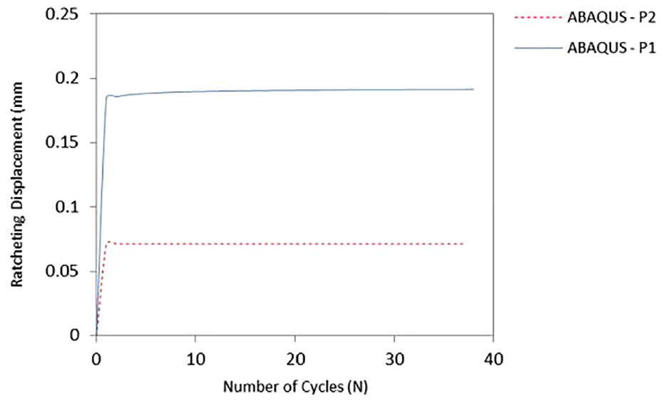
Numerical diagram of ratcheting displacement in terms of the cycle number for Samples P1 and P2.

Numerical diagram of ratcheting displacement in terms of the cycle number for Samples P1, P3, and P4.

Numerical diagram of ratcheting displacement in terms of the cycle number for Samples P1, P5, and P6.
Figure 20 indicates that the number of elements does not profoundly impact the obtained results. Overall, using the isotropic/kinematic combined hardening model of Abaqus software and considering the hardening parameters of Table 4 can simulate the behaviors of Samples P1, P3, and P4 with acceptable accuracy. On the other hand, there is no good agreement between the numerical and experimental results for Samples P2, P5, and P6, in which the accumulated ratcheting displacement has been low in the experimental analysis.
A more detailed look at Figures 21–23 reveals that, similar to the experimental results, the accumulation of ratcheting displacement in the sample decreased with increasing thickness. The numerical and experimental results show identical mechanical behaviors since increasing the number of cutouts in the selection increases the displacement of accumulated ratcheting in both analyses. Accordingly, in the numerical results, increasing the number of cutouts from one circular cutout with a diameter of 8 mm to two circular cutouts, each with a diameter of 8 mm, increases the ratcheting displacement by about 120%. Also, increasing the number of cutouts from two circular cutouts with a diameter of 8 mm to four circular cutouts, each with a diameter of 8 mm, increases the ratcheting displacement by about 65%. Moreover, more ratcheting occurs in the samples with square and triangular cutouts than in circular cutouts. Notably, the samples with square and triangular cutouts in the initial cycles have about 16 and 26% more ratcheting displacement than those with circular cutouts. The nonlinear isotropic and kinematic hardening were used for simulating the specimens in ABAQUS. The software could have performed better in the specimens in which the ratcheting was insignificant. Also, the used coefficients of hardening used in the simulation were the same, which led to some differences in the analysis.
Conclusion
In summary, the effect of cutout numbers, cutout shapes, and thickness on the ratcheting behavior of SS304 sheets subjected to cyclic axial loading was investigated in the current study. The experiments were performed on six specimens with different shapes and cutouts numbers using Instron 8502 device. ABAQUS software conducted a numerical analysis for the specimens under cyclic axial loadings. The Isotropic/Kinematic nonlinear hardening model and the FEM method were considered to obtain results in the simulation. Besides, a careful comparison was also made between the numerical and experimental results. It was revealed that a rise in cycles causes more accumulation in the ratcheting displacement. Then, the diagram slope reaches zero after a characteristic cycle, and the accumulated ratcheting displacement is saturated. The slight difference between the diagram loops in the higher cycles represented a decrease in the ratcheting displacement rate. As the thickness of the sheet increases, the ratcheting displacement decreases due to the increase in the cross-section area and reduces the stress created in the sheet. Increasing the sheet thickness up to two times in size led to decreasing the accumulated ratcheting displacement by 14.47%. The ratcheting displacement variation for the minimum force was 0.3998, which started from the first cycle and continued up to 0.6581 within 160 cycles. In total, the accumulated displacement was 0.2583, and the maximum value of displacement force for the first cycle started from 0.5623 and continued until 0.8519 in 160 cycles. In this case, the displacement force was 0.2896. The cutout numbers directly affected the increased ratcheting displacement created in the sheet and its rate. The main reason is that more cutouts increase stress concentration and bring dislocations and small cracks around the cutouts. The ratcheting displacement created in the sheet with the triangular cutout was more considerable than the rest due to the more stress concentration (square and circular cutouts). Also, this parameter in the sheet with the square cutout is more in value than the sheets containing circular cutouts. This is due to the plastic deformation caused by the sharp roots in the square and triangular cutouts, which leads to the formation and spread of cracks around them. According to the presence of four sharp roots in the sample with a square cutout, the rate of increase in the ratcheting displacement of this sample with a part of the diagram with a constant slope is higher than the sample with a triangular cutout. The obtained results were compared to the numerical ones using FEM a good agreement was observed. The error of the numerical results based on the experimental ones was 15%. Since the results presented in the literature confirm the findings, the results of this research are reliable in terms of accuracy and authenticity. It will be essential for future research to investigate the effect of sheet dimension on its ratcheting behavior. Also, the temperature effect on the ratcheting behavior of the sheets under cyclic axial loadings or transverse stress is of great importance.
Footnotes
Appendix
Acknowledgements
Malayer University in Malayer is greatly acknowledged for providing advanced computational facilities and supporting all costs of this research.
Handling Editor: Chenhui Liang
Declaration of conflicting interests
The author(s) declared no potential conflicts of interest with respect to the research, authorship, and/or publication of this article.
Funding
The author(s) received no financial support for the research, authorship, and/or publication of this article.