
Abstract
This study was performed to analyze the forming fracture of crash box with extruded Al6060-T6 profile. Deep drawing test was performed to evaluate the formability of the extruded profile. For the various specimens, deep drawing tests were repeated to measure the maximum stroke at which fracture did not occur. The finite element analysis for the deep drawing tests was performed to calculate the principal strain through the obtained maximum stroke. The forming limit diagram for the design of the concave forming shape was calculated through the obtained principal strains with the FEA. The forming shape was optimized by using the design variables and FLD by using the FEA. The design variables are the central curvature, the lateral curvature, and the forming depth. The tools were made with the optimizing model and the crash box has been formed without fracture.
Keywords
Introduction
Currently, the automobile market is actively researching for light weight material. The research is conducted to apply aluminum profile to various parts such as frames and bumpers.1–5 As shown in Figure 1, the crash box is installed between the bumper beam and the floor side member at the front of the vehicle body. This serves to absorb the impact energy applied to the vehicle.

Aluminum crash box and assembled bumper. 6
Aluminum of 6000 series is an age hardening alloy material. The physical properties of this material can be controlled through precipitation in the metal structure by heat treatment. 7 In order to form the crash box with the extruded Al profile, there are two methods: performing aging treatment after hot forming processing and performing aging treatment before cold forming processing. In the former case, there is a risk that the shape is deformed after aging treatment. The latter has a high possibility of forming fractures in the material because aged aluminum material increases in tensile strength and decreases in fracture strain. 8
In this study, the 6000 series aluminum profile is extruded through the hot direct extrusion process. Due to the high temperature above 480°C and the frictional heat between aluminum and die in the extrusion process, the solution treatment is carried out in the extrusion. Then age hardening is applied to the extruded profile after extrusion.
Because the extrusion and the forming processes of the crash box do not proceed continuously, the latter forming method is used. So, there is a high possibility of forming fractures like cracks in the cold forming with the 6000 series aluminum profile.
There are lots of studies combining forming limit diagram (FLD) and finite element analysis (FEA). Djavanroodi and Derogar 9 evaluated the FLD of Ti-6V-4Al and Al6061-T6 plates obtained by hydrodynamic deep drawing test using Hill-swift and NADDRG models in ABAQUS. Kumar et al. 10 evaluated the FLD of Al2014-O obtained by Nakazima test and confirmed whether the analysis was possible with FEA. Duan et al. 11 developed a microstructure-based FEA for FLD prediction of heterogeneous Al5018-O sheet. It was confirmed that the results of FEA using MSC Marc and Nakazima test values agree well. Heldari et al. 12 confirmed the prediction of FLD change according to temperature of Al6063 sheet using ABAQUS and Nakazima test. The results showed that with the increase in temperature, the FLD moved upward and sheet forming was improved. These studies used FEA as a method to measure FLD more easily. However, the applications of the FLD, such as new design in field, were not performed and there is no local forming technology for profiles. 13
This study was performed to analyze the forming fracture that occur when cold forming of crash box with Al6060-T6 extruded profile was proceeded. Deep drawing test was designed and performed to evaluate the formability of the extruded profile. The maximum stroke without fracture was confirmed by the tests. The FEA was performed up to the maximum stroke obtained by the tests and the principal strain was calculated. Then, the FLD was calculated with the obtained principal strains.
The concave forming shape of the crash box was de-signed through the design variables of the forming shape. The FEA of the various forming models was performed and the results were analyzed using the FLD. The forming shape of the concave was designed by the minimizing the possibility of the forming fractures with the FLD. To verify the de-signed model, the tools for the development model were machined and the cold forming have been performed and the formings were checked in the fracture.
Formability of the extruded Al6060-T6 profile
Forming of crash box
There is a concave shape in the middle of the crash box as shown in Figure 2. The thickness of the crash box is 2.6 mm. This forming shape increases the impact resistance of the crash box and has a function of inducing the bumper beam to deform in a specific direction when subjected to impact. However, in the cold forming of crash box with the extruded profile, the various forming fractures occur as shown in Figure 3.

The forming shape and section of the crash box.

Various fractures of the Al6060-T6 crash box. 6
Formability of the extruded Al6060-T6 profile
The flow stress of extruded Al6060-T6 profile was obtained through the tensile test as shown in Figure 4. The tensile specimen was obtained from the crash box in Figure 2. The other mechanical properties of Al6060-T6 refer to the database of DEFORM-3D as shown in the Table 1.

Flow stress of extruded Al6060-T6 profile.
Mechanical properties of Al6060-T6.

The formability evaluation was performed through the deep drawing test. 14 The cylindrical punch with the curvature, the die and the blank holder that can fix the specimen with springs were designed as shown in Figure 5(a). It was manufactured as tools to apply the universal testing machine (SFM-600kN) as shown in Figure 5(b). Specimens were obtained from the extruded profile in Figure 2, and four types of specimens were prepared: circle specimen with a diameter of 151.2 mm; rectangle specimens with a width of 151.2 mm; a length of 46.25, 37.8, and 28.35 mm; a thickness of 2.6 mm as shown in Figure 6. The blank holder force was set to about 5000 N, the speed of the punch was set to 1 mm/s, and the friction constant was set to 0.12.

(a) Drawing of deep drawing tool; (b) Machined deep drawing tool.

Specimens for deep drawing test.
After the deep drawing test was repeatedly performed to record the maximum stroke at which fracture does not occu r, the FEA was performed up to the maximum stroke of each test in DEFORM-3D. The maximum principal strain (major strain,


Result of deep drawing simulation in DEFROM-3D.
Result of deep drawing test and simulation.


FLD of extruded Al6060-T6 profile.
Verification of FLD
In order to verify the FLD in shown as Figure 8, the formings of the crush box with the fractures in the field were analyzed. The existing cold forming models have various curvatures and forming depths of the forming shape and were designed without a specific design variable. The appearances of forming fractures are shown in Table 3. Various fractures such as micro-cracks and cracks visible to the naked eye were confirmed.
Forming shape of existing model. 6
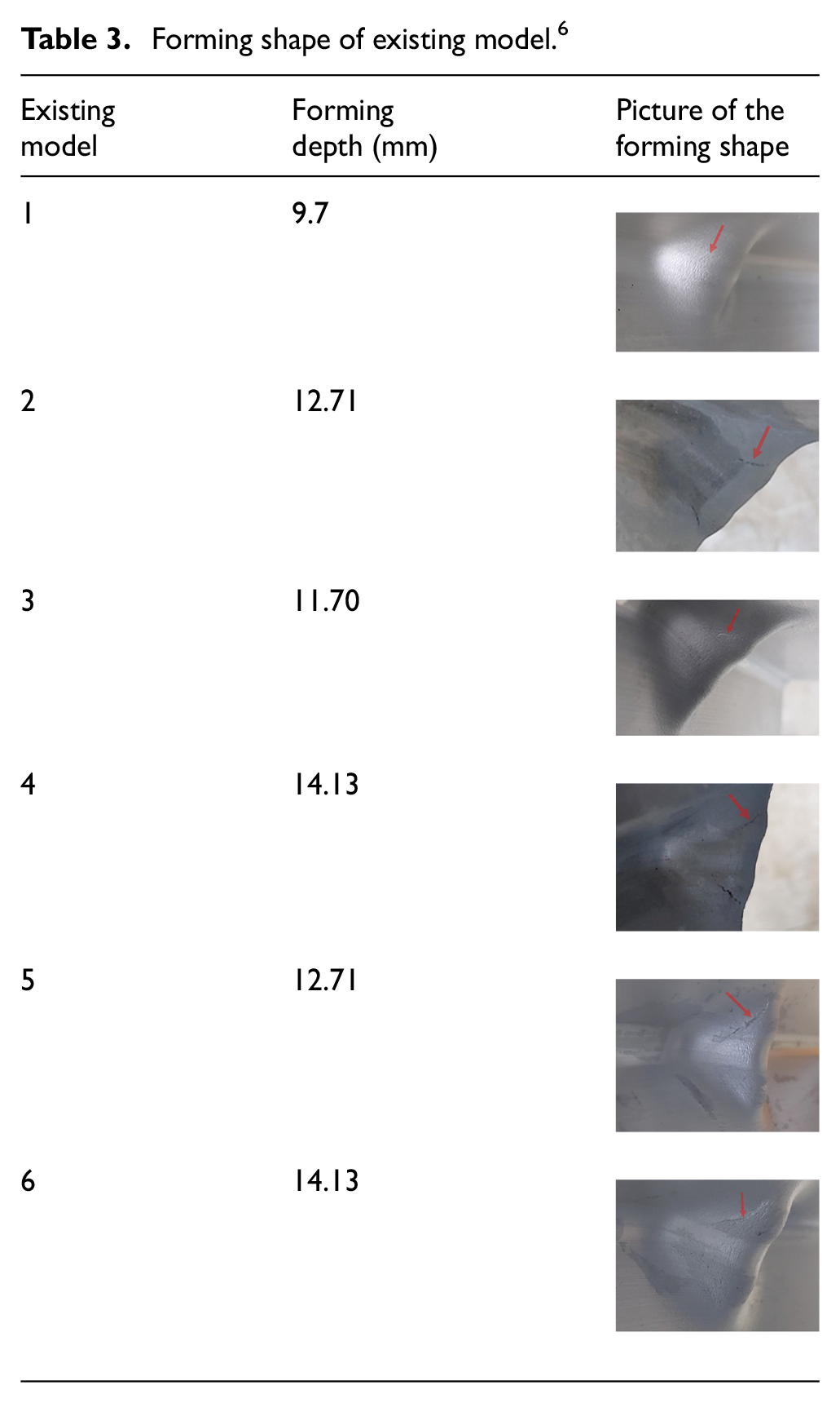
FEA was performed to evaluate the forming process of the existing models in Table 3. The punch speed was 5 mm/s and the friction constant was set to 0.12. Figure 9 shows an example of forming process and its results of FEA. Table 4 shows the values of the principal strain on the fracture surface of six types of existing models.

Result of forming simulation in DEFORM-3D.
Simulation result of the existing model.

Figure 10 shows that the results of Table 4 are substituted into the FLD of Figure 8. The principal strain coordinates of all models in which fracture occurred are located above equation (1). The deeper the forming depth, the more severe the size of cracking tends to be.

FLD of simulation result of existing model.
Design of forming shape
Design variables and modeling
In order to design the concave forming shape of the crash box as a constant standard, three design variables were determined: central curvature (

Method to design the concave forming shape.
The presence of absence of cracks can be identified through the FEA and the FLD as shown in Figures 8 and 10. To determine the design variable, the object function with equation (1) was set as the distance value from equation (1), and negative distance value means that it is located under equation (1).
Design of new model
The new models were designed with reference to the three design variables determined using the method in Figure 11. After setting the forming depth of 14.13 mm as a standard, 20 new models were designed by modifying each design variable at a certain rate. Table 5 shows the design variables of the new models.
Simulation and calculation result of new design.
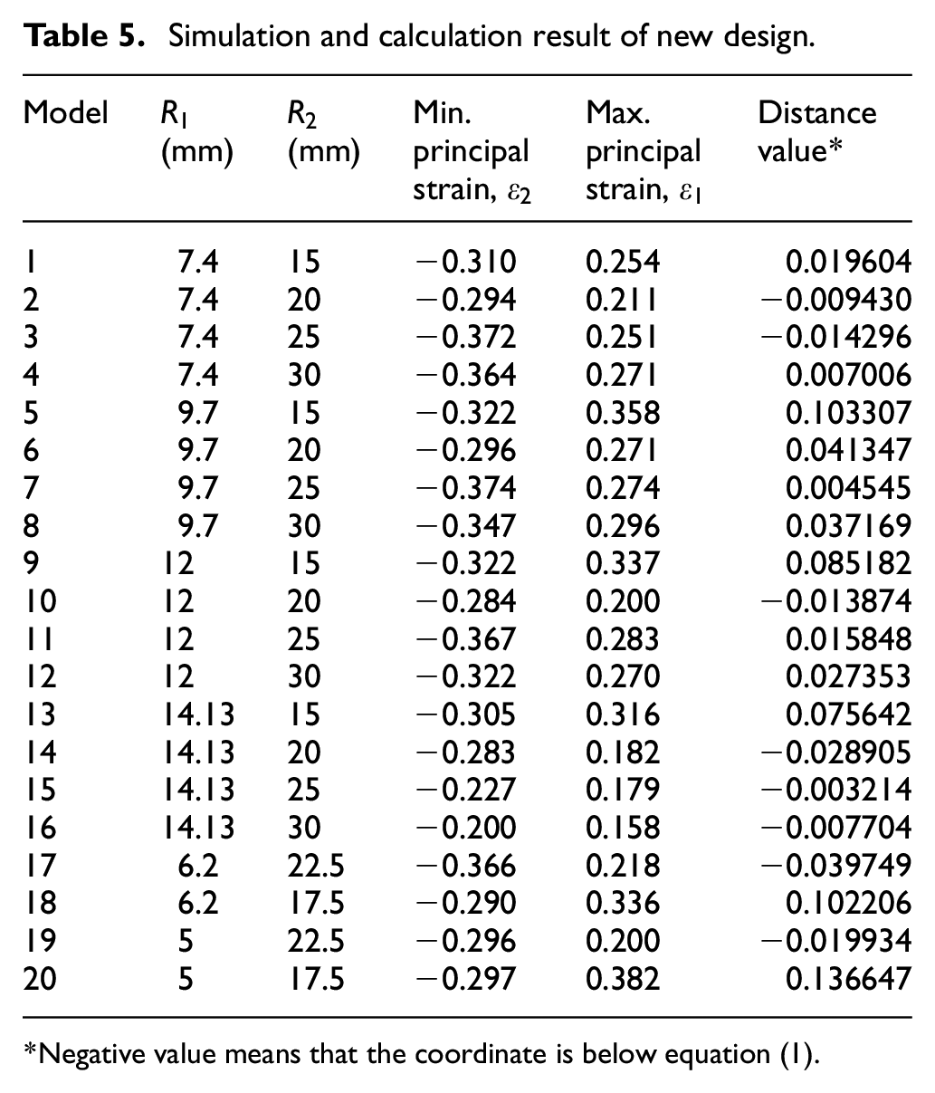
Negative value means that the coordinate is below equation (1).
The FEA was performed in the same way like the existing models in Table 3. Table 5 shows the calculation results of the minimum and maximum principal strain, respectively, and the distance between the point and the equation (1). Figure 12 shows the results of Table 5 are substituted into the FLD of Figure 8. As a result of the evaluation, design model no. 17(−0.039749) was selected.

FLD of simulation result of new models.
Optimization design variables
In the design model, no. 17, obtained in Figure 12 (central curvature of 6.2 mm, lateral curvature of 22.5 mm, and forming depth of 14.13 mm), the curvature of each design variable was corrected at a certain rate. The optimization method selects the variable with the smallest distance value obtained by analyzing the closest design variable to the design modification target. At this time, the optimization was repeated until the decrease in the distance value was 0.0004 of less. The FEA of 18 models were performed in this way, and each design variable and calculated distance values are shown in Table 6.
Calculation result of optimizing design.

Figure 13 shows the results of Table 6 are substituted in the FLD of Figure 8. As a result of the optimization, a smaller value was obtained compared to the distance value of the new model no. 17. The design model, no. 17-17(−0.044858), was selected.

FLD of simulation result about optimizing model: (a) optimization result of the Model 17 and (b) the detail of the result.
Prototype evaluation
Modeling of the design
The design model 17-17 obtained in Figure 13 is selected as the development model. The design variables of the development model are the central curvature of 6.0 mm, the lateral curvature of 21.96 mm, and forming depth of 14.13 mm. The punch and die were modeled according to the con-cave shape design method of Figure 11, and these models are shown in Figure 14.

Development model: (a) punch and (b) die.
Prototype forming
The design modeling in Figure 14 was made into tools to be applied to press forming. The extruded Al6060-T6 profile after the cutting process was completed was formed using a 250 ton mechanical press. The punch and die assembled in this press and the forming process are shown in Figure 15.

Cold Forming of the crash box: (a) machined tools and (b) forming process using mechanical press.
Evaluation the prototype
The result of forming the prototype is shown in Figure 16. As a result, a normal prototype without cracks both inside and outside was obtained.

The crash box after forming: (a) prototype and (b) outside and inside of forming shape.
Conclusion
This study was performed to analyze the forming fracture of crash box with extruded Al6060-T6 profile. The FLD was drawn up using the deep drawing test and FEA, and the development model was selected by optimizing model through design variables using FEA. This was manufactured with forming tools, and a prototype was formed to determine the presence or absence of fractures, and it did not occur. The conclusions obtained through this study are as follows.
(i) A study was performed that cold forming of the Al6060-T6 extruded profile using the FEA in the same way as for sheet material forming.
(ii) The forming limit diagram was drawn up with the results obtained through the FEA, and this was verified through forming process. The deep drawing test and the forming process of crash box use the same extruded profile and are formed under similar stress state. The error of the result obtained by analyzing the processes is reflected equally within the FLD, so its influence is offset. As a result of the actual study, the information on the FLD was valid.
Supplemental Material
sj-zip-1-ade-10.1177_16878132231165903 – Supplemental material for Study on the forming fracture of the crash box with extruded Al6060-T6 profile
Supplemental material, sj-zip-1-ade-10.1177_16878132231165903 for Study on the forming fracture of the crash box with extruded Al6060-T6 profile by Seungchan Ma and Young Choi in Advances in Mechanical Engineering
Footnotes
Handling Editor: Chenhui Liang
Declaration of conflicting interests
The author(s) declared no potential conflicts of interest with respect to the research, authorship, and/or publication of this article.
Funding
The author(s) received no financial support for the research, authorship, and/or publication of this article.
References
Supplementary Material
Please find the following supplemental material available below.
For Open Access articles published under a Creative Commons License, all supplemental material carries the same license as the article it is associated with.
For non-Open Access articles published, all supplemental material carries a non-exclusive license, and permission requests for re-use of supplemental material or any part of supplemental material shall be sent directly to the copyright owner as specified in the copyright notice associated with the article.