
Abstract
Due to the complexity of the process, there is no single solution for determining the motors, gearboxes and structures of a robot manipulator according to the desired dynamic performance while minimising both the deflections in the structure during the dynamic motion and total robot weight. The solution of this integrated drive-train and dynamic structural optimisation problem is generalised for three degrees of freedom (DOF) robot manipulator via Non-Dominated Sorting Genetic Algorithm II (NSGA-II) to obtain the Pareto front of any desired robot manipulator overall conceptual design, including motors, gearboxes and thicknesses of the links. A flexible body dynamic simulation model was created in the MATLAB Simmechanics environment. The flexible bodies were defined via lumped parameter estimation method, which allows observation of the deflections in links during the dynamic motion. A library containing technical data related to motors and gearboxes was created to be utilised in the optimisation algorithm. The method accelerates the time-consuming iterative process for obtaining optimum conceptual design solutions for a dynamic system and allows for easy modification of design parameters and constraints. It also makes the algorithm suitable for different types of dynamic system designs.
Keywords
Introduction
The two most important aspects in the design a robot manipulator are drive-train, consisting of motors and gearboxes, and the structure. This is due to their direct effect on the robot’s total weight, position accuracy and dynamic performance. Increasing structure thicknesses also decreases the endpoint error due to the deflection, but unfortunately it also increases the total robot weight and decreases the dynamic performance. This may lead to a new selection requirement for the drive-train to overcome this drop in dynamic performance. Selecting a more robust and heavier drive-train increases dynamic performance, but it also increases deflection and endpoint error. Therefore, an increment in structure thicknesses may be necessary to overcome the increasing deflection problem. This complexity causes many time-consuming iterations in the design stage requiring an optimum conceptual design algorithm. This study aims to utilise Non-Dominated Sorting Genetic Algorithm II (NSGA-II) to create an optimum solution set for three DOF robot manipulator conceptual design by selecting motors and gearboxes from the drive-train library, and determining the link thicknesses. The objectives in this process are to minimise total robot weight and endpoint error caused by the deflections in the links during the motion. There are also many different algorithms that can be used to obtain the optimum solution set for a multi-objective optimisation problem, such as NSGA, NSGA-III, Multiple Objective Particle Swarm Optimisation (MOPSO), etc. In this study, NSGA-II is preferred because it is a commonly used method for multi-objective optimisations. However, in future work, for comparison, other methods can be used to solve the same problem.
A library that contains 31 motors and 675 gearboxes was created. The gearboxes consist of only Harmonic Drive type gearboxes because Harmonic Drives have zero backlashes, and they are very lightweight. There are approximately 675 different Harmonic Drives available in their catalogue and all were included in the drive-train library. The selected motors were all from the same brand. The most common ones were selected for the drive-train library, while the excessively large or small ones were eliminated. Hence, 31 different size motors are available; the library can also be extended with varying brands of motors and gearboxes, according to the designer’s needs. All necessary technical information for motors and gearboxes is written in matrix form in MATLAB. All motors and gearboxes are sorted according to their weight, and numbered accordingly. These matrices are used by the optimisation algorithm to select the motors and gearboxes.
The optimisation process has two conflicting objectives: minimising total robot weight and minimising the endpoint error, caused by the deflections in the links during the motion. The design variables of the optimisation problems are motor numbers, harmonic drive gearbox numbers and link thicknesses. Equations (1a) and (1b) show the objective functions while equations (2a) to (2c) show the design variables of the optimisation problem. NSGA-II is a commonly used method to solve multi-objective optimisation problems, but there are also other methods. One of these is combining all objectives with a specified weight multiplier in a mono-objective function and finding a unique solution. However, the Pareto front presents all possible optimum solutions for all objectives and allows the designer to choose a solution instead of being restricted to a single solution. Finally, this study shows how the Pareto front of two conflicting objectives is generated via NSGA-II for a three DOF robot manipulator optimum conceptual design under certain design parameters (desired velocity, payload, trajectory, kinematic lengths, etc.). Three DOF robot manipulator configuration can be seen in Figure 1. Design optimisation has been widely studied in recent years to increase robot manipulators’ efficiency and dynamic performance. In the literature, robot design optimisation has been studied as either structural, controller, drive-train, dimensional, workspace optimisation or different combinations of these variables. They might be divided into two groups in terms of their optimisation methodology. The first group is using directly single objective function or, combines objectives with a weighted sum method to create a mono-objective function. The second group is creating a Pareto front via a multi-objective optimisation method such as NSGA-II, etc.


Three DOF robot manipulator.
There are several papers in the first group (mono-objective optimisation for robot design). One example is an integrated structural and controller optimisation study. 1 Another study about drive-train optimisation based on dynamic performance, 2 focusing only on cost, dynamic performance and the lifetime of the drive-train. Another drive-train optimisation study in the literature 3 focused on trajectory planning and its effects on drive-train selection. A further study on drive-train optimisation 4 focused on the optimisation cycle in MATLAB, and uses ADAMS co-simulation for dynamic simulation. The study involved a limited drive-train library including only a few motors and gearboxes. The objective function is minimising the total weight. The same authors later added dimensional optimisation to their existing drive-train optimisation work in another study.5,6 Kinematic length optimisation is considered with drive-train optimisation, again with the objective of minimising the total weight. The same authors finally succeded in creating an integrated drive-train, dimensional and static structural optimisation for the same five DOF robot arm. 7 They used MATLAB for optimisation cycle, ADAMS for dynamic simulation and ANSYS for static strength analysis, that is, they used three different types of software for co-simulation. The objective was again to minimise the total weight and the drive-train library was very limited. Another study about drive-train and structural optimisation 8 is very similar to the previously discussed one, except for the absence of dimensional optimisation. Another study in the literature also focuses on the drive-train and structural optimisation 9 whose objective function is minimising the total weight. Both drive-train and structure performances depend on constraints. Drive-trains are optimised via rigid body dynamic simulation. Consecutively, structure performance is simulated via flexible bodies. This method works like a co-simulation. Another study focused on robot link parameter optimisation using kinematic and dynamic performance indices. 10 Further studies considered dimensional optimisation to increase the rigidity of the structure of the robot arm, 11 and workspace optimisation for a robot manipulator, 12 and robot optimisation with flexible body dynamic simulation.13–15 All these studies have only one objective function, and they use the weighted-sum method to convert all objectives to a single objective function.
The second group which directly uses a multi-objective optimisation method such as NSGA-II has several examples in literature. One of them is the structural optimisation of a planar robot for a task specification (pick and place operation). 16 The aim was to minimise the required torques by optimising the lengths and cross-sectional areas of the structure, and compare the results of NSGA-II, Multi-objective genetic algorithm (MOGA) and Multi-objective differential evolution (MODE). Another group of studies focuses on multi-objective optimisation of robot design or gripper via NSGA-II. One of these examines gripper design optimisation, 17 and another obtains the Pareto front of a parallel robot design. 18 Finally, there is a study that obtains the Pareto front of spray-painting robot design in literature. 19 The design parameters are the geometric lengths, and the objectives are minimising energy consumption, transmissibility and compactness. Another study concerns the dimensional optimisation of a surgical manipulator. 20 The aims are to minimise the collision among the mechanical arms and enlarge the range of arms. This study selected NSGA-II for that multi-objective optimisation problem. Another study employed a concurrent optimisation of drive-train, dimensional and control in a trajectory planning study,21,22 and the multi-objective optimisation problem was solved via NSGA-II. The three objectives were to minimise the total weight, the execution time and the tracking error. Using drive-train library, they also created a closed-loop control system and considered drive-trains with trajectory and tracking errors. There was no structural analysis. The robot dynamic equations were formulated for a three DOF planar robot manipulator rather than creating the dynamic simulation environment in ADAMS or Simmechanics.
This study can be added to the second group which uses multi-objective optimisation methods such as NSGA-II. It has also several contributions to the literature. It was unique in considering both total weight and endpoint errors during dynamic motion. Also, the study was notable for creating a flexible body dynamic simulation environment instead of making a static strength analysis in ANSYS; there was no co-simulation or need for extra software and, dynamic performance is simulated simultaneously with structural performance via flexible body dynamic simulation environment. Co-simulation is a very time-consuming process, and it separates dynamic performance analysis and strength analysis. However, the drawback was that the flexibility of the links creates a vibration with a negative effect on dynamic performance. On the other hand, the forces acting on the bodies during the dynamic motion are very different from the static case. Therefore, flexible body dynamic simulation gives more realistic results. This study focused more on conceptual design than the final design and, the extensive drive-train library allowed many different sizes of robot design and thus presented a more generalised algorithm. It also presents a Pareto front via NSGA-II for an integrated drive-train and dynamic structural optimisation problem. Table A1 compares this study with the most relevant studies in the literature (see Appendix A).
Drive-train library
There are 31 different DC motors and 675 different Harmonic Drive gearboxes in the drive-train library. The technical parameters of them are listed in Tables 1 and 2, respectively. These parameters are written in matrix form in MATLAB. As shown inTables 1 and 2, each motor and Harmonic Drive has 20 parameters. Therefore, the matrix dimension for motors is
Maxon DC motor technical data.

Harmonic Drive technical data.


Harmonic drive general sizes.
In Table 2, Harmonic Drive numbers represent the order of the Harmonic Drive weights as in motor numbers. Sizes are the name of the Harmonic type. Moment of inertia effects are added into account in dynamic simulation. Ratios are also used both in optimisation algorithm and dynamic simulation. In Simmechanics, weights are used in dynamic simulation, and the average and the momentary peak torque limits are used to compare these with the dynamic simulation results. Torsional stiffness torques and torsional stiffnesses are used while calculating the twist angle of the Harmonic Drives during the dynamic simulation. Therefore, Simmechanics considers the twist angle effects while calculating the endpoint error during the dynamic motion. Maximum input velocities (oil) are compared with the necessary velocities. Harmonic Drives can be used with either oil or grease, which have different velocity limits. In this study, all harmonic drives are considered to work with oil. Finally, Harmonic Drive sizes are used to create the geometric shapes of the Harmonic Drives in Simmechanics. Other parameters in Tables 1 and 2 were used but are available for future works.
NSGA-II for obtaining Pareto front of three DOF robot manipulator conceptual design
The Pareto front has as many axes as the number of objectives. Therefore, it presents the values of all individuals in objective functions. Non-Dominated Sorting Genetic Algorithm II (NSGA-II) is a commonly used method to obtain the Pareto front of a multi-objective optimisation problem. In this study, there are two conflicting objective functions to be optimised. The first is to minimise the total robot weight, and the second is to minimise the maximum endpoint error due to the deflections of the links while the robot follows the specified trajectory. The endpoint errors are calculated instantaneously during the dynamic motion by Simmechanics using lumped parameter estimation. Minimising the maximum value of these errors is the second objective of this multi-objective optimisation problem. There are nine parameters to be determined to obtain the Pareto front. The parameters are three motors and three Harmonic Drive gearboxes, and three thickness values for links. The links are selected as hollow cylinders since it is only a conceptual design optimisation. After determining the conceptual design, the topology optimisation can be used for links to create the final design. The flowchart of the proposed optimisation method can be seen in Figure 3. The NSGA-II for three DOF robot manipulator conceptual design multi-objective optimisation method is explained step by step below.
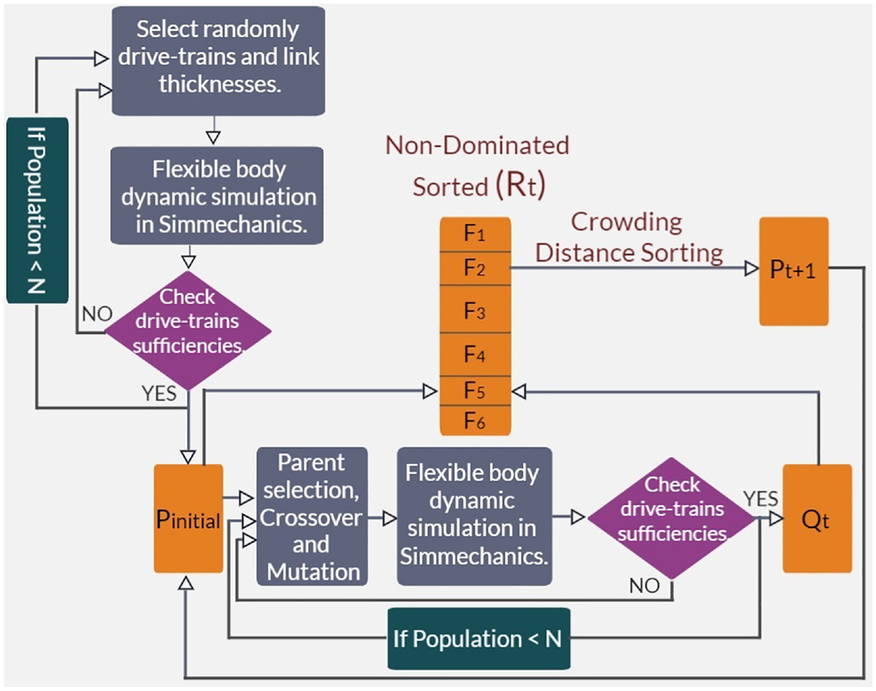
Flowchart of the proposed method.
Step 1: Creating the initial population:
The initial population


The selected Harmonic Drive gearboxes should reach the necessary velocities depending on design parameters and trajectories. The velocity comparison can be seen in statements (5) and (6). After these comparisons, all Harmonic Drives unsuitable for the selected motor are eliminated, and the lightest Harmonic Drive from the new list is selected for that motor. Finally, the drive-train selection is completed.


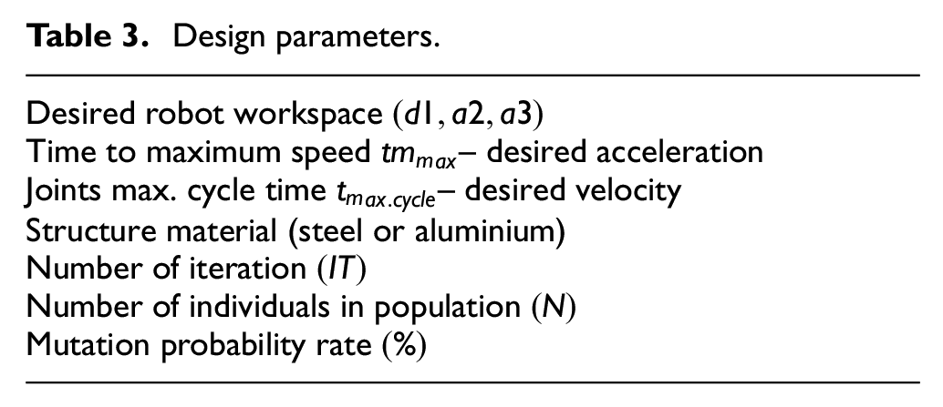
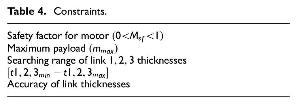
After selecting the Harmonic Drive gearboxes, the thicknesses of the links are selected randomly in the specified searching range in the design parameter. The final step is determining the motor – Harmonic Drive groups and the thickness values to be assigned to specific links. This is a serial robot arm, and it is clear that the first link needs higher torques and thicker links, therefore, the most powerful motor-Harmonic Drive (HD) group and the thickest link are assigned. The less powerful motor-HD group and the thinnest link are assigned to the third link. Hence, the randomly selected individual is prepared. However, each randomly selected individual is added to the initial population after checking whether it has potential as a solution. All individuals are sent initially to the Simmechanics flexible body dynamic simulation environment with predetermined trajectories to obtain the necessary torques. The robot arm is tested for six different serial motions in dynamic simulation, all designed for the most challenging motions, which allows the highest necessary torque values to be obtained. One of the motions is accelerating the arm to the opposite direction of gravity when all links are extended horizontally. All trajectories in the motions are designed with a cubic velocity profile, and they also depend on design parameters such as desired maximum velocity, desired acceleration, etc. Then, necessary torques for each link are obtained, and these torques are compared with the motor’s capacities by considering the motor safety factor
Design parameters.
Constraints.
Step 2: Calculating endpoint error during the motion via lumped-parameter estimation
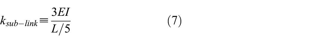
Lumped parameter estimation method allows observation of the deflections in the bodies during the dynamic motion. In Simmechanics dynamic simulation environment, the links are meshed into five equal sub-links, as seen in Figure 4. All sub-links are connected via a spherical joint element, and the spring constants of all sub-links, calculated as seen in equation (7), are defined into spherical joint elements. Hence, endpoint error due to the deflection in the links can be obtained during the motion after flexible body dynamic simulation. The relative difference between endpoint positions obtained from simulation and desired (rigid body motion) endpoint positions directly gives the endpoint error during the motion.
Meshed link.
Step 3: Domination rules and sorting the individuals for NSGA-II
Minimising the total robot weight and the dynamic endpoint error are two objective functions of this optimisation problem. First of all, these two objective values are determined for all individuals in the population. Total robot weight is calculated by summing the weights of the motors, Harmonic Drive gearboxes and links. An individual’s maximum endpoint error is obtained after a flexible body dynamic simulation environment. The simulation gives all the endpoint errors during the motion, and the maximum value of these errors is also the maximum endpoint dynamic error. The next step is sorting the individuals. All individuals are according to their values in objectives. This comparison determines the number of times an individual is dominated by another, and the number of times an individual dominates another. Individuals who have never been dominated compose the Pareto front. Domination rules are illustrated in statement (8), and then the individuals are sorted from non-dominated to the most dominated.

Step 4: Crossover, mutation and obtaining a new population
The next step is creating a new population

Multiple-point crossover method is used in crossover operation. The number of points and crossover points are selected randomly in each crossover operation. After crossover, mutation operation is performed for selected chromosomes according to the mutation probability rate given in the design parameters. Then, the last offspring is sent to the flexible body dynamic simulation to determine whether it has sufficient drive-trains. If the related offspring passes the drive-train test, it is accepted as an individual for the new population
Step 5: Crowding distance sorting

Crowding distance sorting method. 23
Example of NSGA-II for Pareto front of a conceptual robot design
The design parameters and constraints of the example conceptual robot design can be seen in Tables 5 and 6, respectively. The suitable trajectory for design parameters and constraints can be seen in Figure 6. The trajectory has the cubic velocity profile and includes the most critical motions for motors, gearboxes and structure. Figure 7 illustrates the evolution of the Pareto front, including final one. The comparison of the initial and the final population in Pareto front can be seen in Figure 8, which also includes the dominated individuals. Figure 9 shows only the final Pareto front.
Design parameters of example optimisation.
Constraints of example optimisation.


Trajectory (cubic velocity profile).

Evolution of the Pareto front.

Initial versus final population in Pareto front (including dominated individuals too).

Final Pareto front.
The final Pareto front includes 24 individuals. These individuals and their values in objective functions are listed in Table 7. For example, from the Table 7, the designer might select solution eight. The designed robot view of solution eight can be seen in Figure 10. The motors’ sufficiency and endpoint error graphs during the motion for solution eight can be seen in Figures 11 and 12, respectively. Finally, Table 8 shows the general results of solution 8.
Final Pareto front list.

The selected example solution.

Robot view of Solution 8 in Simmechanics.

Necessary torques versus motors and harmonic drive gearboxes capacities for solution 8.
Endpoint error during the motion for solution 8.
General results of solution 8.

Conclusion
This study obtains the Pareto front for a three DOF robot manipulator conceptual design via NSGA-II. This case study can be adapted to any multi-objective optimisation of a dynamic system design. There are two conflicting objective functions: (a) minimising the total robot weight and (b) the endpoint error occurring due to the deflection in the links. A drive-train library is used to select the motors and harmonic drive gearboxes in the optimisation process. The lumped parameter estimation method enables the identification of the bodies’ deflection and endpoint error during the dynamic motion. Designers can use this type of optimisation process to increase performance, decrease energy consumption and accelerate the design process. In addition, Pareto optimality presents many different solution choices depending on the objectives, from which the designer can choose. This design method is also fastest and most practical for obtaining an optimum conceptual design for a dynamic system. Finally, the variable-dependent algorithm allows for easy modification of design parameters and constraints. It also makes the algorithm suitable for different types of dynamic system designs.
Contributions: The contribution of this study to the literature can be explained as follows.
In this study, the Pareto front of a three DOF robot conceptual design is achieved via NSGA-II satisfying two conflicting objective functions: minimum total robot weight, and endpoint errors due to the deflection in the links during the dynamic motion. The design variables to be selected in the optimisation process are motor numbers, Harmonic Drive gearbox numbers and structure thicknesses.
Unlike previous studies, the flexible body dynamic simulation environment used in this study allows observation of the deflection in the bodies during the motion using lumped parameter estimation. Therefore, this suggested method utilises the simulation of dynamic motion simultaneously with structural analysis, known as flexible body dynamic simulation. This also helps to eliminate time-consuming co-simulation processes used in software such as ANSYS, ADAMS, etc. In addition, co-simulation neglects the effect of dynamic motion on the structures and the effects of vibrating structures on the dynamics of the system. In the literature, co-simulation is used to perform strength analysis only for the static case. Thus, this proposed method requires no other software, such as ANSYS, ADAMS, etc. in co-simulation to observe the deflection in the links.
Finally, the suggested method focuses on optimisation of conceptual design rather than the final design, that is, it does not consider bearings, assemblies, nuts, screws, etc. In addition, the drive-train library is more extensive than the other studies in the literature, resulting in a more basic and flexible optimisation algorithm than other approaches. These features, give this proposed method a wider application range than other studies in the literature.
In future work, this optimisation method can be adapted for six DOF robot manipulator. Kinematic optimisation can be incorporated into the existing system, and topology optimisation can be used to create the final optimum design of the robot manipulator.
Footnotes
Appendix A
Comparison of the most relevant studies.

| Ref. no | SO a | CO b | DTO c | DO d | TO e | DS f | SA g | Simulation type | Software | Objective function | OA h |
|---|---|---|---|---|---|---|---|---|---|---|---|
| This study | X | X | Flexible | Flexible | Simultaneous | MATLAB Simmechanics | Multi* | NSGA-II | |||
| 1 | X | X | Rigid | Fem | Co-simulation | MATLAB Adams MSC-Nastran | Consecutive Mono** | Proposed method | |||
| 7 | X | X | X | Rigid | Fem | Co-simulation | MATLAB Ansys | Mono*** | Nangradient based | ||
| 8 | X | X | Rigid | Fem | Co-simulation | Adams Ansys | Mono*** | Complex method | |||
| 9 | X | X | Rigid | Flexible | Consecutive | MATLAB Simmechanics | Mono*** | Heuristic method | |||
| 21 | X | X | X | Math. modelling | None | Math. modelling | Not identified | Multi**** | NSGA-II |
Structural optimisation.
Controller optimisation.
Drive-train optimisation.
Dimensional optimisation.
Trajectory optimisation.
Dynamic simulation.
Structural analyses.
Optimisation algorithm.
Minimising total weight and endpoint error caused by the deflections in the links during the motion.
Consecutive optimisation. Mono-objective for structure (maximise stiffness with mass constraint). Mono-objective (weighted sum method) for the controller (minimise settling time and overshoot).
Minimising total weight under constraints.
Minimising total weight, execution time, and tracking error.
Acknowledgements
The authors would like to thank anonymous reviewers for their valuable comments and suggestions for revising the paper.
Handling Editor: Chenhui Liang
Author contributions
The authors confirm contribution to the paper as follows: SE created the idea of multi-objective optimisation of a robot conceptual design. MOG performed the formulations and analyses of this study under the supervision of SE. Finally, SE and MOG prepared the manuscript. All authors reviewed the results and approved the final version of the manuscript.
Declaration of conflicting interests
The author(s) declared no potential conflicts of interest with respect to the research, authorship, and/or publication of this article.
Funding
The author(s) received no financial support for the research, authorship, and/or publication of this article.
Data accessibility statement
All the data used in this paper can be obtained upon request to the corresponding author.