
Abstract
As a complex space enveloped surface, the tooth surface of dual-lead helical gear enveloping hourglass worm is characteristic with difference tooth profile, unequal pitch and variable tooth thickness. To grasp the geometry characteristics and precision manufacturing method of it, the analytical method for toroidal helix is presented. The mathematical model of toroidal helix is developed, and the geometry characteristics of helix angle, axial tooth thickness, and tooth surface undercutting are analyzed. The helix angle of toroidal helix presents the convex shape, and the undercutting characteristic is affected by the pressure angle, helix angle, transmission ratio, and normal modulus. Based on the toroidal helix of tooth surface, the precision manufacturing method is proposed, and the measuring method is developed. The hourglass worm sample was manufactured and measured, and the transmission accuracy of hourglass worm drive is tested. The results show that the manufacturing and measuring method of toroidal helix is effective and feasible.
Keywords
Introduction
The tooth surface of dual-lead helical gear enveloping hourglass worm is a complex space enveloped surface, and it with difference tooth profile, unequal pitch, and variable tooth thickness. 1 The toroidal helix is completely different from the usual helix, which is characterized with constant pitch and constant tooth profile. Though studying the geometric characteristics of toroidal helix and understanding the sharpening and undercutting, it can provide theoretical guidance and reference for the parameter design, manufacturing and accuracy testing of this novel dual-lead helical gear enveloping hourglass worm drive.
Scholars have discussed the tooth surface geometric characteristics of various worm gearing. Mohan and Shunmugan 2 analyzed the geometrical performances of toroidal worm drive, and simulated the worm wheel tooth profile generated by different axial sections. Dudas et al. 3 developed the arched profile spiroid worm gear drive, and proposed a new manufacturing technology for the spiroid worm with lathe. Zhao et al.4–7 proposed the novel double anchor ring secondary enveloping toroidal worm gearing, the tooth flank modification theory, tooth contact, and mismatched performance are investigated. Deng et al.8–12 proposed a novel non-backlash rolling body enveloping toroidal worm gearing, as well as studied the optimal process of machining complex surfaces and the meshing characteristics. Yang et al. 13 proposed a method to generate the spiral groove of double enveloping worm gear hob, and established the geometric model of its rake face. Rui et al. 14 presented a method to investigate the grinding interference of hourglass worm wheel hob relief surfaces, and the design method are proposed to avoid grinding interference. Simon 15 studied the LTCA of cylindrical worm gearing with the tooth surface manufacture errors and the assembly errors of shaft misalignments. Falah and Elkholy16,17 analyzed the performance of TCA on single-enveloping toroidal worm gearing with assembly errors, and developed the stress analysis as well as load sharing with transmission errors. Polowniak et al. 18 presented a novel construction method to the hourglass worm wheel tooth profile, and it is enveloped by the double enveloping worm gear hob with the rectilinear and concave-convex. Seol and Chumg 19 and Seol and Park20,21 investigated the geometric interference of worm drive with the oversized hob and localized contacts. Kacalak 22 proposed a novel structure of non-backlash worm gearing, which backlash can be adjusted or eliminated though the specially structure designed Moeso proposed a whirl-machining process to manufacture the toroidal worm, and the whirl-machining model of toroidal worm is developed through CNC machining machine, as well as the benefits of whirl-machining process in toroidal worm manufacturing are verified. 23 Chen et al.1,24 and Zheng et al. 25 proposed a novel worm drive, which is consisted of a dual-lead helical gear and an hourglass worm, as well as the meshing characteristics of backlash-adjustable and wear-compensable are developed. However, as a novel hourglass worm, we have an insufficient understanding of the geometry characteristics and precision manufacturing method.
This paper presented a tooth surface analytical method for the dual-lead helical gear enveloping toroidal worm, and the mathematical model of toroidal helix is developed, as well as the geometry characteristics of helix angle, axial tooth thickness, and tooth surface undercutting are analyzed. The precision manufacturing method and measuring method is proposed based on the toroidal helix, and the toroidal worm sample was machined and measured, as well as the transmission errors is tested.
Mathematical model of toroidal helix
The toroidal helix is the intersecting line of two surface, which are the tooth surface of dual-lead helical gear enveloping hourglass worm and surface of annular rotating, as shown in Figure 1. Where, R2 is the radial value of tooth surface, rj is the generatrix torus arc radius of toroidal rotary surface, and rf2 ≤ rj ≤ ra2, rf2, and ra2 are the torus arc radius of the addendum and dedendum of tooth surface, respectively. And a is the generating central distance.

Toroidal helix of hourglass worm: (a) 3D model and (b) geometric relation.
The annular revolving surface in Figure 1 can be represented as:

Where,

Combining the equation (1) with the equation of hourglass worm tooth surface, which has deduced in document1,24, the toroidal helix equation can be obtained as follows:

Geometry characteristics of toroidal helix
Helix angle
The geometric relationship of the tangent vector
Geometric relationship of helix angle.
According to the differential geometry, the tangent vector of point P on toroidal helix can be represented as follows:

Where,
As shown in Figure 2 and the definition of helix angle, the calculation formula of helix angle on the toroidal helix can be obtained as follows:

A dual-lead helical gear enveloping hourglass worm drive for the solar power tracking system is selected as an example, and the geometric parameters is shown in Table 1.
Geometric parameters.

All the subsequent calculation parameters are same as above. The change curves of the left-hand and right-hand helix angles on the pitch circle, the dedendum circle and the addendum circle of this novel hourglass worm can be obtained through the analysis and calculation, and it is shown in Figure 3.

Helix angle change curves: (a) left-hand tooth surface and (b) right-hand tooth surface.
From Figure 3, the both helix angle of this tooth surface is a convex shape, it first increases and then decreases, the change trend of the dedendum circle is obvious, the pitch circle is the second, while the changes of the addendum circle are relatively small. The maximum differences of the toroidal helix angle changes on the left-hand tooth surface of addendum circle, pitch circle and dedendum circle is 3°, 2.47°, and 2.12°, respectively. While the maximum differences of the helix toroidal angle change on the right-hand tooth surface of addendum circle, pitch circle, and dedendum circle is 2.84°, 2.33°, and 2.29°, respectively.
Tooth thickness
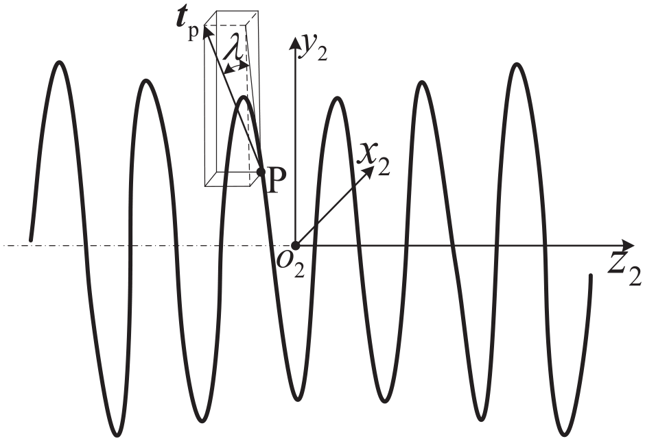
The thickness of this hourglass worm can be controlled by fixing one tooth surface and rotating a certain angle of the other tooth surface. The relationship of conversion principle and tooth thickness control are shown in Figure 4. Curve L1 is the toroidal helix on the right-hand tooth surface. Curve L2 is the initial toroidal helix on the left-hand tooth surface, the curve L2 is rotate around the axis by an angle to obtain the curve L3, and the tooth thickness relationship between L1 and L3 is correct, P1, P2, and P3 are the intersections of curve L1, curve L2, and curve L3 with the throat plane respectively, and

Conversion principle of circular helix: (a) circular helix (b) points on plane x2o2y2.
Bringing the
Curve L3 is obtained by turning curve L2 by an angle
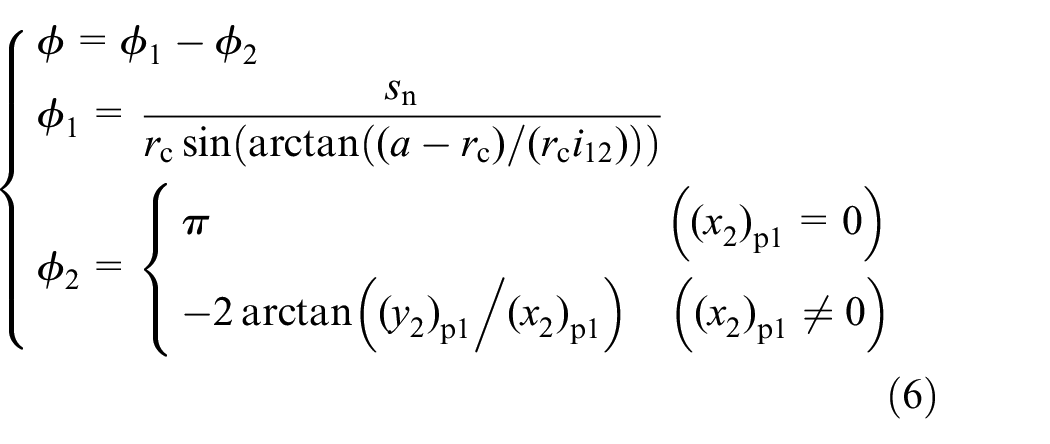
In formula (6),
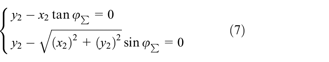
The hourglass worm can be intercepted by plane ∑ passing through axis

Axial tooth profile of hourglass worm.
In Figure 5, the axial tooth thickness of hourglass worm should satisfy the follows:
Combining the worm tooth surface equation with equation (7), the axial tooth profile of tooth surface can be confirmed. By intersecting the circular arc
As shown in Figure 6, the axial tooth thickness of dual-lead helical gear enveloping hourglass worm tooth surface is:


Geometric relationship of axial tooth thickness.
The variation of axial tooth thickness on the addendum circle, the pitch circle and the dedendum circle of dual-lead helical gear enveloping toroidal worm can be obtained, as shown in Figure 7. The axial tooth thickness is distributed in sinusoidal wave shape, and the change trend of the addendum circle is significant, the change of pitch circle is gentle, as well as the change of tooth dedendum circle is extremely small. The maximum difference of axial tooth thickness change on the addendum circle, the pitch circle, and the dedendum circle are 0.332, 0.108, and 0.020 mm, respectively. Therefore, the dual-lead helical gear enveloping hourglass worm is not prone to the phenomenon that the tooth tip becomes sharp.

Axial tooth thickness curve of hourglass worm.
Undercutting curve
The enveloping curve of the contact lines in the developing process is the undercut curve. If the root tangent enters the effective area of tooth surface, the undercut phenomenon will occur on and resulting in poor meshing quality, and reducing the carrying capacity and shorting the service life.
Taking the parameters Table 1 as an example, it can be calculated that the root tangent of the enveloping toroidal worm right-hand tooth surface, and it can be shown in Figure 8.

Undercutting curve on the left-hand tooth surface of hourglass worm: (a) horn helix and (b) points on end face.
In Figure 8, PC is the intersection of the root tangent and the end face, and its coordinate value is
If
If
Therefore,

Taking the aforementioned parameters in Table 1 as an example, the influence laws of main geometric parameters such as helix angle, normal modulus, transmission ratio, and pressure angle on the undercutting are analyzed, as shown in Figure 9.

Variation rule of undercutting curve: (a) helix angle, (b) transmission ratio, (c) normal modulus, and (d) pressure angle.
The pressure angle and helix angle have very little influence on the tooth undercutting. The change of transmission ratio and normal modulus will lead to the change of dedendum arc radius of hourglass worm, so it has a slight influence on tooth surface undercutting. Therefore, the tooth surface of dual-lead helical gear enveloping hourglass worm is less prone to undercutting.
Manufacturing of toroidal helix tooth surface
3D model of toroidal helix tooth surface
Based on the toroidal helix model in equation (3), the toroidal helix of hourglass worm in Table 1 can be calculated by the MATLAB, and the two sides of toroidal helix is shown in Figure 10(a). Based on the toroidal helixes, the tooth surface can be developed by the surface fitting in Siemens Unigraphics NX, and the hourglass tooth surface is shown in Figure 10(b). The contact lines are shown in Figure 10(c) and (d), and there are five pairs of teeth in line-contact.

3D model of hourglass worm tooth surface: (a) toroidal helix, (b) tooth surface, (c) contact line on left-hand tooth, and (d) contact line on right-hand tooth.
Processing method of toroidal helix tooth surface
Though the toroidal helix, the tooth surface can be milled by the five-axis linkage vertical machining center, as shown in Figure 11. Figure 11(a) show the toroidal helix machining path on the tooth surface, and it is simulated in the HyperMill as shown in Figure 11(b).

Machining path of toroidal helix: (a) machining path on tooth surface and (b) simulation of tooth surface machining.
Manufacturing of toroidal helix tooth surface
The tooth surface was manufactured by the high-precision five-axis machining center DMU 60 mono BLOCK, and the machining processing site is shown in Figure 12, as well as the roughness is tested by the Beijing Time-top SF200, and the tooth surface roughness is Ra 0.653 μm.

Manufacturing of tooth surface.
Measuring of toroidal helix tooth surface
Profile errors of tooth surface
The free scanning function is used to obtain the tooth shape data points of hourglass worm, and it can be shown in Figure 13.

Detection principle of tooth surface.
In Figure 13, the position ① is the initial reference position of the probe, the position ② is the moving schematic diagram of the scanning process, and the axial tooth profile of different circumferential angles can be measured by rotating the C-axis.
The tooth surface is measured by the Klingelnberg P26 in Figure 14(a), and the measuring points is shown in Figure 14(b). The measured data points need to be converted to the actual data through probe radius compensating. Through the data processing,26–28 the tooth surface deviations can be obtained in Table 2.

Errors measuring of tooth surface: (a) measuring site and (b) measuring points.
Tooth surface deviations of tooth surface.

In Table 2, Δfmax is the maximum deviation of tooth surface, while ΔfΣ is the average deviation. The maximum deviation is 24.7 μm on the left-hand side, while the average deviation is 12 μm. The maximum deviation is 17.2 μm on the right-hand side, while the average deviation is 9.3 μm.
Transmission errors of hourglass worm drive
The reducer prototype was assembled and the transmission accuracy was tested, as shown in Figure 15.29–31

Transmission accuracy test bench: (a) testing principle and (b) testing site.
The rotation angle of worm was collected though angle encoder I, while the rotation angle of worm wheel was collected though angle encoder II. Based on the angle encoder, the input angle φ1 and the output angle φ2 can be obtained, and the transmission error is ε = φ2 − φ1/i21, where i21 is the transmission ratio.
The transmission errors of this prototype are measured as shown in Figure 16. In Figure 16, the clockwise rotation refers to the right-hand tooth surface of hourglass worm meshing with the left-hand tooth surface of dual-lead helical gear, and it is abbreviated as “cw,” while the counter-clockwise rotation is abbreviated as “ccw.” In the clockwise rotation, the short-cycle transmission error is 22″, while the long-cycle is 59″. And in the counter-clockwise rotation, the short-cycle transmission error is 53″, while the long-cycle is 81″.

Transmission errors.
The long-cycle transmission error takes the shape of sinusoidal wave, which is caused by the eccentricity error of dual-lead helical gear. And the short-cycle transmission error is 22″ in the clockwise, while that is 53″ in the counter-clockwise. That is because the maximum deviation is 24.7 μm on the left-hand tooth surface of hourglass worm, which is the meshing tooth surface on the counter-clockwise rotation, while the maximum deviation is 17.2 μm on the clockwise meshing tooth surface, as shown in Table 2.
Conclusions
(1) The helix angle of the hourglass worm toroidal helix shows the convex trend, and the change trend of root circle is obvious, while the addendum circle is relatively small.
(2) The axial tooth thickness is distributed in sinusoidal wave shape, and the change trend of addendum circle is significant, while the root circle is extremely small.
(3) The pressure angle and helix angle have little effect on undercutting of tooth surface, while the transmission ratio and normal modulus have a slight influence on the undercutting.
(4) The tooth surface can be precision manufactured though the toroidal helix, and the hourglass worm sample show that the maximum deviation of tooth surface is 24.7 μm, while the maximum transmission error of hourglass worm drive is 81″.
Footnotes
Handling Editor: Chenhui Liang
Declaration of conflicting interests
The author(s) declared no potential conflicts of interest with respect to the research, authorship, and/or publication of this article.
Funding
The author(s) disclosed receipt of the following financial support for the research, authorship, and/or publication of this article: This research was funded by the Science and Technology Research Program of Chongqing Municipal Education Commission (KJZD-K202104401, KJZD-K202204401), Robot and Artificial Intelligence Technology Youth Science and Technology Innovation Research Team Project.