
Abstract
In this paper, the research status of three types of wheel-rail interaction force measuring approaches, that is, IWS, ground measurement method and indirect measurement method, are summarized systematically. According to the measuring locations, the IWS can be determined by measuring the bending strain of the axle, as well as the strain of the wheel web. The measuring principle, bridge assembly method, calibration test and sensing technology of IWS are introduced respectively. This paper introduces the ground measurement method of measuring·wheel-rail force by arranging sensors on the rail and other track components to test their response, and the indirect methods for wheel-rail forces measurement are reviewed, which is derived from inertial force and suspension force of wheelset according to the force states of the wheelset. The advantages and disadvantages of the IWS, the ground measurement method and the indirect measurement method are analyzed. The investigation results show that the measuring principle of the IWS is relatively mature, and its measurement accuracy mainly depends on the manufacturing technology, bench calibration and signal acquisition. Future development of the IWS tend to realize the non-destructive, wireless, continuous and accurate measurement of the wheel-rail forces and contact points locations.
Introduction
The core that determines the dynamic performance of a railway vehicle is the interaction force between the wheels and the rail. The wheel-rail force is transmitted to the bogie and the car body through the suspension system, which is very important for the stability of snaking, riding quality, wheel tread wear and derailment safety. At the same time, the wheel-rail force also causes problems such as rail head side wear, rail disease, loose fasteners, rail corrugation, etc. 1 Therefore, both domestic and foreign vehicle/track dynamics standards require the evaluation of wheel-rail forces and related indicators. The wheel-rail force can be decomposed into three mutually vertical components, namely the vertical force, the lateral force against or away from the wheel rim, and the longitudinal force parallel to the rail, as shown in Figure 1. Wheel-rail vertical force is mainly affected by factors such as wheel out-of-round, rail corrugation, rail joints, line distortion, etc. It is mainly used to assess the derailment risk caused by vehicle damage to the track and wheel load reduction; Wheel rail lateral force and axle lateral force are mainly affected by wheel rail creep, hunting motion and curve passing. It is mainly used to assess the risk of rail rollover and the stability of vehicle snaking motion. The ratio of wheel-rail lateral force to vertical force is used to judge the safety of derailment; The longitudinal force is mainly affected by the longitudinal impulse, traction and braking force of the train, it determines the wheel-rail adhesion performance of the heavy-duty train.1–5

Traditional wheel-to-wheel-rail force measurement method. 61
Railway transportation is constantly developing in the direction of high speed, heavy load, multiple systems and new structures, which puts forward higher requirements on the accuracy of wheel-rail force measurement, and has become the focus of research in recent decades. Because the wheel-rail contact point moves quickly on the rail as the wheel rotates at a high speed, it is impossible to directly measure the wheel-rail force in the contact spot, but the wheel-rail force will be transmitted to the axle and bogie through the vehicle spokes, which will also at the same time acting on the rails. Therefore, the current wheel-rail force measurement methods mainly include the force-measuring wheel-set method based on the strain of the wheel web or axle, based on the rail waist strain, and the indirect wheel-rail force measurement method. The location of each method test is shown in Figure 1.
This article is mainly divided into four parts to summarize: (1) The development status, measurement principle, calibration test and sensing technology of IWS; (2) measuring principle and calibration test of force measuring rail method; (3) indirect measurement method of wheel-rail force principles and judgments; (4) Dynamic analysis of development.
Force measurement of wheel IWS method
Development status of IWS
The Swedish Interfleet company is one of the world’s professional manufacturers of IWS products. It has been manufacturing IWS since the 1950s and is the first company in the world to develop IWS products. At present, there are mainly two typical products of Interfleet. The IWT3 type is shown in Figure 2(a) and the IWT4 type is shown in Figure 2(b). Both products calculate the wheel rail contact force by sticking a strain gauge on the wheel web to measure the deformation near the contact spot, but the two products are technically very different. The IWT3 type IWS was developed in the 1950s and is a traditional product. It is an IWS for intermittent measurement and is suitable for measuring wheel-rail force in the low-frequency range of low-speed vehicles. IWT3 performs patching by looking for special deformation areas of the web. These areas are only sensitive to the lateral force (or vertical force), but not to the vertical force (or lateral force), and then group the bridges to output signals and process the data afterward. It is necessary to establish a decoupling equation to realize the decoupling of lateral force and vertical force.

Mainstream products of Swiss Interfleet Company 2 : (a) IWT3 and (b) IWT4.
The IWT4 type IWS is a fourth-generation technical product. Compared with the IWT3 type IWS: (1) IWT4 outputs the signals of all strain gauges in real time, collects the strain data of all positions in the circumferential direction of the wheel at the moment of wheel-rail contact, and then passes the data recognition system calculates the current wheel-rail force according to the pre-calibrated test results; (2) The main feature of the IWT4 type IWS is that the algorithm training must be carried out in the laboratory before use; (3) IWT4 is not limited by the structure of the wheelset, which reduces the influence of the structure of the wheelset on the measurement plan and structure; (4) IWT4 no longer needs to drill holes on the spokes, and replace it with a signal wireless transmission system, which reduces the arrangement of signal lines and power supply cables. Its working principle is to paste the acceleration sensor or strain gauge onto the tested equipment, and the sensor is connected with the encoder through the corresponding conditioning module. Then the encoder wirelessly transmits the collected signal to the user through the signal transmitter. The equipment on the axle is powered by electromagnetic induction. As shown in Figure 3. The test cost is greatly reduced, and the production cycle of the IWS is also shortened. The IWT4 type IWS system has passed the certification of the German Federal Railway Administration (EBA), and has been tested with a large axle load of 37.5 t. 2
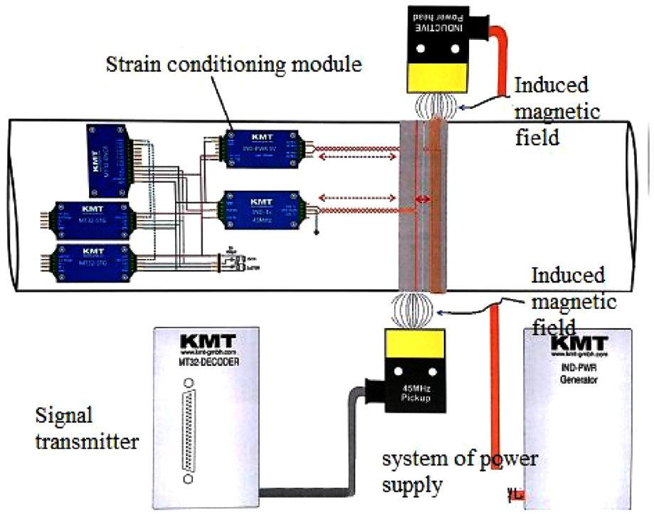
Working principle of wireless transmission system.
MeRaN IWS is the latest generation of IWS product developed by Austrian company PJ Messtechnik (PJM). MeRaN is suitable for straight roulette, radial corrugated roulette and bell roulette. MeRaN adopts electronic control, supplemented by finite element calculation and simulation, and selects the appropriate calibration method through the iterative calculation of linear equations according to the load conditions to obtain more accurate results. Through the use of software and hardware specially developed by PJM, the related detection units of the IWS are simpler than other systems.
Japan’s RTRI (Railway Technical Research Institute), Korea’s rapid rail transit and Australian Railway Corporation have all carried out research on wheel rail force measurement methods. It can be seen from the research papers published by their domestic scholars that they are all carrying out research on continuous wheel rail force measurement methods.6–10
Cetest, a third-party testing laboratory in Spain, has developed an IWS11,12 suitable for high-speed vehicles. The wheel set also measures the wheel rail force by decoupling means based on the sensor system, and records the wheel rail contact force in three directions at the same time. The system mainly uses strain gauges to directly measure the wheel stress without being affected by the wheel rail contact position. The system does not need any modification for the tested wheel set, and can customize the solution according to the customer’s requirements, so as to meet any wheel set. The IWS can collect vertical force, transverse force and longitudinal force in real time, the acquisition error rate is less than 1%, and the sampling frequency can reach 1 ksa/s. The adaptive communication of wheel set can be realized by using optical fiber telemetry technology. It is calibrated and verified on a special test-bed to simulate the dynamic and static response under actual conditions. The maximum wheel rail contact stress can reach 200 kn and the maximum angle of attack at the contact position can reach 2000 rpm.
TTCI (Transportation Technology Center, Inc.) of the United States has developed IWSs suitable for large axle load trucks.13,14 The dynamometer wheelsets developed by ttci can be used from light load trains to 125 ton heavy load trains. Ttci can manufacture test wheelsets consistent with the customer’s locomotive specifications, lease or sell them to the other party, so as to obtain the relevant analysis data required to complete the test. Ttci provides reliable analysis report, more cost-effective price, faster and accurate test, and can provide wheel sets of any size according to customer requirements. The National Research Council of Canada (NRCC) realized the identification of wheel rail force in three directions through IWS, which were applied to heavy-duty freight and passenger vehicles respectively (Figure 4), and successfully exported the products to European countries such as Spain. 15

NRCC-CSTT dynamometer wheel set of National Railway Administration of Canada. 15
Zeng et al. of China Academy of Railway Sciences16,17 began to study the theory and practice of continuous measurement technology of IWS at the end of last century. At the initial stage of the research, the wheel rail force was identified by using the wheel spoke strain method. In recent years, the traditional IWS method has been mature and applied to the real vehicle for line tracking test. At present, they began to study the non-contact collector ring, and the test accuracy is constantly improving. Xiao et al. 18 studied the strength of the dynamometer wheel set after drilling, and concluded that the strength will indeed decrease after drilling, but it can still meet the standard requirements. Chu et al. 19 studied the error of IWS caused by centrifugal force through finite element simulation, and evaluated the dynamic frequency response characteristics of dynamometer wheel set. Hu et al. 20 studied a new IWS calibration test-bed.
Chen21–28 studied the measurement method based on neural network and genetic algorithm, established the IWS calibration test-bed, and finally proposed the method to improve the test accuracy of IWS and the patch scheme. Ren and Chen29,30 studied the change characteristics of wheel rail contact state, data processing method and wireless IWS detection system in detail. Finally, they carried out experimental research on IWS and verified the measurement method proposed in this paper. Lai et al. 31 studied a method for measuring wheel/rail force at high frequency. In order to eliminate the influence of wheel-pair modal resonance, based on traditional FIR filter, an all-phase filter is designed by considering all the subsections when the filter coefficients are fixed in length. The all-phase filter designed can be used to calculate comparatively accurate high-frequency wheel-rail force.
Mr. Jin Xincan’s team of Beijing Jiaotong University has systematically studied the force measuring wheelset method in recent years. Under his guidance, Zhang 32 studied the application of improved BP neural network in wheel rail force measurement technology, and He 33 studied and designed the IWS calibration test-bed, Wang 34 did a research on the calibration method of the high-speed straight-web plate IWS, Kang 35 also applied the IWS in the paper, and studied the load spectrum and stress spectrum of the 400 km/h high-speed wheel axle. Li 36 developed the IWS calibration test-bed and studied the calibration technology. Gong et al.37,38 studied the IWS method of wheel axle combination method. Taking the 1:5 wheel set model as the research object, she studied the reasonable patch bridge assembly scheme and designed the static calibration test-bed.
Load measuring wheel set bridge assembly method
The IWS can be divided into three categories according to different measuring positions, namely: (1) identify the wheel rail force according to the axle bending strain; (2) Identify the wheel rail force according to the wheel web strain; (3) Wheel rail action point measurement.
Calculate wheel-rail force by measuring the bending strain of the axle
Deutsche Bundesbahn (Deutsche Bundesbahn) scholars focus on the study of the IWS with strain gauges arranged on the axles, they calculate the bending moment of the axle by measuring the bending strain of the axle, and then analyze the relationship between the bending deformation of the axle and the load in the three directions to calculate the wheel-rail contact force. Figure 5 shows the strain gauge bridge scheme adopted by the axonometric IWS. The Wheatstone full bridge method is adopted, and the strain bridge is in a 90° orthogonal form. In order to reduce the test error caused by the change of the position of the contact point of the wheel set by the axonometric method, it is usually necessary to stick a strain gauge on the web to identify the bending deformation of the axle caused by different loads, such as the load generated by the vehicle on the axle during traction and braking, etc, requires complex decoupling algorithms and calibration tests to identify the magnitude of the contact force acting on the wheels. This is also the reason why axonometric force measurement wheelsets are difficult to apply to power wheelsets, which limits its engineering application scope.

Bridge assembly method of axonometric IWS. 21
The disadvantage of this method is that it is assumed that the axle is a Saint-Venant beam, and it is necessary to calibrate the force measuring wheel several times before use, determine the conversion coefficient between strain and load, and arrange strain gauges on multiple sections. Due to structural space constraints, it is difficult to measure the strain at all desired locations. At the same time, the error sources of the IWS based on the axle strain method are also many, and the axle strain is inevitably affected by the position of the wheel-rail contact point. The mass inertia of the wheelset between the contact point and the measuring point of the strain gauge will also cause measurement errors. Therefore, it is also necessary to measure the vibration acceleration of the wheelset to eliminate this error. Due to the large difference in the quality of the wheel sets of different structures, the degree of influence of the inertia varies greatly, which makes the accuracy of the IWS of the axonometric method far inferior to that of the spoke-type IWS. Furthermore, the strain signal of the axonometric IWS is easily affected by the rotation of the axle, that is, the strain amplitude output is the modulation signal of the axle speed, However, compared with the signal amplitude modulation phenomenon of the spoke-type IWS, the output signal demodulation of the axonometric method is easier. The axonometric method based on the bending deformation of the axle will be affected by the first-order bending mode of the axle (about 80 Hz), so the sampling frequency of the axonometric force wheel set is not higher than 40 Hz. The first-order bending mode of the wheel is about 200 Hz, which is significantly higher than the bending mode of the axle.
Calculate wheel-rail force by measuring the strain of the wheel web
The IWS based on the strain of the web can be divided into the IWS for intermittent measurement and continuous measurement in terms of measurement principle. The early IWS were measured intermittently, and the wheelset rotated one revolution to get a peak value. Only the peak value of the waveform reflects the effective value of the force on the wheel-rail contact point. When continuous recording of the wheel-rail force is required, it can only be determined approximately by the envelope of the waveform, the accuracy of the test is not high, and it cannot accurately reflect the changing process of wheel-rail force. Continuous measurement means that under the constant wheel-rail force, the output of the measuring bridge is constant and is not affected by the rotation of the wheelset. The bridge assembly method for continuous measurement of wheel-rail lateral force mainly uses the orthogonal principle of two sets of sine and cosine signals, and the measurement result has nothing to do with the wheelset rotation angle by obtaining the square sum; the bridge assembly method for continuous wheel-rail vertical force measurement is mainly Using the principle of superposition of two sets of 45°phase relationship triangle waves, continuous force measurement is achieved by summing the two.
The method of identifying wheel-rail contact force through wheel spoke strain originated in the United Kingdom. This is mainly due to the spoke-type wheels used in early British railway vehicles, because the strain measured by the spoke-type wheels is directly decoupled in the lateral and vertical directions. And the spoke strain is not sensitive to the position of the wheel-rail contact point. This method is also widely used on Japanese railways. However, the spoke-type IWS method is not directly applicable to the spoke-type wheel set, so this also limits the scope of its engineering application.
Scholars all over the world have carried out a lot of research on the spoke plate IWS, mainly because the spoke plate IWS does not need to make great changes to the structure of the wheelset itself, which has many advantages:
It is applicable to moving wheelsets and trailer wheelsets, that is, it is not limited by the geometric structure of the wheelset, such as brake disc and transmission system.
It is applicable to independent wheels. Since the independent wheels and axles are not rigidly coupled together, the axle measurement method cannot be used. Therefore, the application range of spoke wheel is much larger than that of spoke wheel.
Because the strain gauge sticks to the spoke plate and is closer to the wheel rail contact point, it is less affected by the inertia of the wheel set structure.
The frequency response bandwidth of spoke plate IWS is much higher than that of axle IWS. It can be used to study various structural vibration and damage caused by wheel rail contact.
It is necessary to study the patch position of the strain gauge on the wheel spoke to determine the radial and circumferential arrangement of the spoke plate IWS. Reasonable arrangement of strain gauges can not only control the components of wheel rail contact force in three directions, but also effectively reduce the modulation and interference of variable output corresponding to wheel rotation. There are many methods for the radial arrangement of strain gauges, 12 which can be selected at the position where the coupling effect of wheel rail transverse force and vertical force is the smallest, or in the area where the response amplitude of strain to transverse force and vertical force is the same, and then the force decoupling can be realized by data post-processing method, or the strain gauge can be arranged in the drilling area on the wheel spoke, This area is most sensitive to wheel vertical forces. Figure 4 shows several typical strain gauge arrangement schemes. It is usually necessary to determine the radial and circumferential arrangement areas of strain gauges in combination with computer simulation techniques such as finite element method. The strain gauges shown in Figure 6(a) are evenly and equally spaced along the circumferential direction of the wheel, and the continuous output of radial strain of the wheel can be realized by adding the output of the used strain; Figure 6(b) shows that only when the corresponding position of the strain gauge moves to a certain position, the measurement or signal output can be carried out, which can eliminate the modulation effect of wheel rotation on the variable signal output. Of course, this method also reduces the frequency response range of the IWS, and this arrangement method is not recommended in engineering application; Figure 6(c) shows that the strain gauges are arranged at 90° on the same radius position. This method can effectively reduce the impact of wheel rotation on signal output, and can also realize the continuous output of wheel rail force. It is necessary to post process the two strain signals, but it is similar to the output of wheel rail force measurement by axial measurement method, and is vulnerable to high-frequency harmonic interference.

Layout scheme of corresponding variable plate of spoke plate dynamometer: (a)scheme of attaching strain gauge in circumferential direction; (b) location of eliminate the modulation effect of wheel rotation and (c) train gauge arranged at 90°. 12
The stress concentration effect can be caused by drilling holes on the wheel web. Using this feature, the vertical force acting on each wheel can be accurately measured, 9 while the transverse force is still obtained by measuring the bending deformation of the web. As shown in Figure 7, four holes need to be drilled to decouple the transverse force and vertical force. Alstom company of France continuously measures the wheel rail force by arranging strain gauges at multiple radial and circumferential positions, making full use of the advantages of the above force measurement method. A total of 32 strain gauges and 16 strain gauges on one side of the spoke plate are used. This method needs to balance the accessory strain caused by wheel inertia, has high output signal-to-noise ratio and the highest response frequency of 100 Hz, but the cost is expensive.

Layout scheme of corresponding variable plate of Web drilling dynamometer. 12
Lucchini company of Italy, together with universities such as the University of Rome and Milan Institute of technology, has developed a new generation of IWS method,3–5 which calculates the wheel rail contact force by measuring the deformation of axle and wheel spoke. At the beginning of the design, the FEM method is used to determine the optimal arrangement scheme of strain gauges. Similarly, 32 strain gauges and 16 strain gauges on one side of the spoke plate are arranged at the same radial position at the same angle (22.5°). In order to identify all components of wheel rail contact force (six in total), strain gauges need to be arranged on six different axle sections to measure the vertical and transverse bending deformation of the axle respectively, and two additional strain bridges need to measure the torsional deformation of the axle to identify the longitudinal force. To sum up, strain bridges are arranged for different force components, and the decoupling of each force is realized by data decoupling algorithm. Lucchini IWS method adopts signal wireless transmission system, which improves transmission efficiency and reliability, reduces cable layout and reduces workload.
Application advantages of IWS method:
(1) Provide a method to obtain the wheel rail contact force in real time, and the measurement method is the most direct and the test result is the most reliable; It can measure the transverse force, vertical force and longitudinal force on the left and right wheels of the same wheel set, and identify the specific position of the wheel rail contact point on the wheel profile.
(2) Compared with the wheel rail force measurement technology installed on the track, the IWS method can measure the wheel rail force in real time and continuously, while the wheel rail force measurement technology based on track instrument can only provide the force of the vehicle at the moment when it passes the test position, and is only suitable for monitoring the vibration impact of multiple vehicles at the test point. In order to better monitor the vehicle operation status, The IWS method shall be used.
(3) Through the on-line measurement, storage and data analysis of wheel rail force, the operation safety and stability of vehicles can be evaluated in real time, the track irregularity level can be evaluated, and the real-time status of vehicles and tracks can be provided, so as to realize the on-line monitoring and intelligent operation of vehicle operation status.
Disadvantages of IWS measurement method:
(1) The manufacturing cost of IWS is high. The patch scheme of IWS is complex and takes a long time to make.
(2) The IWS needs to be perforated on the spoke plate, which destroys the strength of the vehicle and is not suitable for long-term use.
(3) The IWS can only measure the low-frequency wheel rail force. Because the calibration process of IWS is quasi-static and the wheel rail force response caused by the modal vibration of wheel set is not considered, it is not applicable to obtain high-frequency wheel rail force IWS.
(4) Calibration experiment is required, and the program is complex. The data directly obtained by the IWS is the strain data at the spoke and other positions. How to connect the strain data with the wheel rail force is the problem to be solved in the calibration test.
Calibration test of IWS
The relationship between wheel rail force and web strain can be obtained through finite element calculation, bench calibration and line test. Using the finite element calculation method and referring to UIC510-5 standard, the wheel rail transverse force and vertical force are applied at the nominal rolling circle, the flange thickness measurement point and the tread 105 mm away from the wheel back respectively. Taking the straight spoke wheel as an example, Figure 8 shows the von Mises equivalent stress distribution and surface radial stress distribution of the wheel when the vertical force and transverse force are applied. It can be seen that the equivalent stress is evenly distributed along the thickness direction when the vertical load is applied, and the surface stress changes sign when the transverse load is applied. When the vertical load is applied, the change of wheel rail contact point has a great influence on the web surface stress, while the transverse force identification is not sensitive to the position of the action point. Therefore, the measuring points and bridge groups can be selected according to the strain distribution of the wheel web.

Stress distribution on wheel web surface.
The IWS calibration test-bed determines the relationship between force and bridge strain by accurately applying wheel rail load. Academy of Railway Sciences 20 TK-LDBD IWS alignment bench realizes independent and combined loading of IWS in vertical, horizontal and vertical directions; Beijing Jiaotong University33,36 carried out strength calculation, modal calculation and strength check of bolted connection for the bearing base platform and gantry of the calibration platform, so as to ensure that the mechanical structural components can meet the loading requirements of load measuring wheelset, and compared the difference between strain wheel based on axle measuring method and wheel strain measurement. The NRC IWS calibration bench in Canada uses hydraulic actuators to load the vertical force and transverse force, and rollers and drive motors are installed under the wheel set to realize dynamic rotation calibration. The author’s team has developed a continuous IWS calibration test-bed, with the specific structure shown in Figure 9. The test-bed meets the functional requirements of temperature and humidity environment, patch process, three-dimensional loading with large load, influence of contact point, dynamic rotation calibration, continuous wheel rail force measurement, high calibration accuracy, and so on.

Continuous dynamometer wheel set calibration test bench.
As a high-precision wheel rail force measuring device, the test accuracy of IWS should generally be controlled within 5%, which puts forward higher requirements for IWS patch, bridge assembly and calibration. In order to ensure the test accuracy, the calibration process of IWS includes bench calibration and line verification. The bench calibration needs to apply horizontal or vertical force step by step to obtain the force strain calibration coefficient matrix, and compare the calculated wheel rail force with the loading force, so as to control the measurement error. The line calibration shall also verify the error between the measured wheel rail vertical force and the actual wheel weight on the straight line, and also verify the wheel weight and unbalanced centrifugal force of the whole bogie when quasi-static passing through the curve.
IWS sensing technology
The strain gauges arranged on the IWS rotate with the wheels at high speed. In order to realize the stress measurement of the rotating parts, there are currently two power supply and signal transmission methods, namely the collector ring and the wireless telemetry. The IWS collecting ring is usually installed on the inner ring of the bearing, and the cable needs to penetrate the axle, which will inevitably cause damage to the wheel set structure, as shown in Figure 10(a). Therefore, the wireless telemetry system has become the development trend of the IWS method in recent years. The Swedish Interfleet 1 adopted the signal wireless transmission system on the fourth generation IWS to avoid drilling holes in the wheel spokes and effectively reduce the signal and the arrangement of the power supply cables. MeRaN uses 32-channel infrared wireless transmission, so there is no need to process the axles in order to install the cable sleeve. Infrared transmission can achieve a great bandwidth and provide a higher data transmission rate while ensuring high digital resolution. Infrared transmission has stronger anti-interference ability than radio transmission, and eight groups of full bridge signals can be transmitted simultaneously through infrared. China Research Institutes have also learned from the mature wireless sensing technology of rotating parts abroad or off-road, as shown in Figure 10(b). The author’s team has introduced Interfleet and KMT wireless transmission hardware equipment to achieve wireless non-destructive measurement of the acceleration, stress and temperature of rotating parts such as wheels, axles and brake discs.

Power supply and signal transmission mode of IWS: (a) collecting ring and (b) wireless telemetry system.
Method of instrumented rail
Train wheel-rail force measurement rail method refers to the method of arranging sensors on the rail or other track components to test its response, thereby evaluating the wheel-rail force. The earliest ground wheel-rail force measurement method was achieved by measuring the deflection of the rail between two sleeper spans, but the under-rail support is elastic, and the track will settle to a certain extent when the vehicle passes by. When measuring the deflection, it is necessary to reduce the settlement displacement, and it is not easy to find a fixed reference position for the installation of the sensor during the measurement. In the 1930s, with the invention and popularization of resistance strain gauges, a method for measuring rail and wheel force based on rail strain came into being, and the method for measuring rail deflection was eliminated. Strain-based measurement methods have become the mainstream and have been used to this day.
The patch scheme of the strain gauges is also constantly being improved. The initial measurement of the force of the steel rail is achieved by the normal stress of the steel rail when it bears the wheel. However, the flexural modulus of the steel rail is relatively high. The sensitivity of the system is too small to evaluate the force by measuring the normal stress, and the change of the wheel-rail contact point has a great influence on the normal stress, so a relatively large error will occur. The shear stress patch method overcomes the above shortcomings and has relatively high sensitivity. Shear stress method, as the name implies, is to obtain the wheel/rail vertical force through the shear stress distribution of the rail. According to the American test data, on the section 10–15 cm from the load point, there is no vertical normal stress and no longitudinal normal stress at the horizontal axis of the rail, which is the pure shear strain state. In the pure shear strain state, the principal stress and shear stress in the direction of the element body are equal. Therefore, the shear stress value is obtained by sticking a strain gauge at the neutral axis of the rail waist to measure the principal stress at that point, and then the load value is obtained through laboratory calibration. The Figures 11 and 12 describe the patch methods of shear method measurement in various countries. 39 This method eliminates the influence of the change of wheel-rail contact points on the test results through the strain gauge group bridges on both sides of the rail. The shear stress method is the mainstream method currently used. Another method is to measure the wheel-rail force by measuring the bending moment difference at the bottom of the rail, but this method is less sensitive than the shear stress method, and the field operation is complicated, so it has not been widely used.

Strain gauge scheme and bridge assembly method in the United States and Canada. 39

Strain gauge scheme and bridge assembly method in France and China. 39
In 1997, Jönsson et al. 40 gave the theoretical basis of arranging strain gauges on the rail to measure the quasi-static wheel-rail force based on the Vlasov thin-walled beam theory and the continuous evaluation based on the stiffness of the smooth sleeper and the theory of rotational elasticity, and used the finite element method. The model was verified.
According to the characteristics of wheel-rail interaction and the constraints of the track system, Zhao et al. 41 proposed a continuous measurement method of wheel-rail horizontal force with steel rail as the sensing element. The continuous test of wheel-rail force is realized by measuring the shear force at the cut-off boundary and the reaction force at the rail bottom. According to the finite element calculation results, the strain gauge is affixed to 10 cm from the midline of the sleeper. The upper strain gauges were connected in series to form the bridge as shown in Figure 13.The method is verified by finite element, laboratory and field tests, as shown in Figure 14.

Bridge assembly method. 41

Wheel/rail force test results. 41
Pan and Zhang of Southwest Jiaotong University 42 designed a continuous wheel-rail force measurement system that measures the strain of the rail according to the force characteristics of the rail when the wheels pass. On both sides of the rail waist, paste the vertical and horizontal bridge according to Figures 15 and 16. Force calculation equations and related factors, and the feasibility of the system is verified through line tests. The validation results are shown in Figure 17.

Patch position. 42

Bridge assembly method. 42

Wheel/rail force test results. 42
According to the characteristics of wheel rail interaction, Li et al. 43 extracted effective wheel rail force data by using the information of ground test data and threshold judgment method. Design an algorithm based on radial basis function neural network to deal with the nonlinear relationship of wheel-rail force at different test units, and train the neural network with the horizontal and vertical forces under the action of different positions of different wheels and different points of action, and realize the wheel-rail Continuous test of force and simulation test for three working conditions. Nong of the State Key Laboratory of Traction Power of Southwest Jiaotong University 44 studied the stress and deformation of steel rails under wheel loads to provide a theoretical basis for measuring wheel-rail forces. After a specific data processing method, the vertical force of the wheel and rail is obtained by the patch group bridge on the steel rail. Hong 39 also used the method of rail-reversed wheel-rail force, the difference is that he used BP neural network for continuous measurement of wheel-rail force, which verified its feasibility. Ding 45 studied the response of the support reaction force at the sleeper and the output curve of the vertical force group bridge, and determined the continuous inversion scheme of the vertical force using the steel rail as the sensing element, and used the support reaction force and shear force compensation. The method accurately inverts the vertical force. Through the distribution of the strain field of the rail under lateral load, the arrangement method of the corresponding strain and the output curve of the bridge group are studied, and the reasonable position of the patch is obtained.
The Huang et al. research group of Central South University defined the high-speed rolling force generated by the wheel on the track as the sweeping force of the train wheel, and the shear strain was measured by pasting a strain gauge at the waist position to obtain the wheel-rail force. According to this idea, the design and construction of the high-speed sweeping force ejection test bed was completed, and the simulation of the high-speed sweeping model of freight car wheels was realized. The influence of the rail support stiffness on the sweeping force was studied through the test bed. Impact and other issues.46,47 Yang 48 of East China Jiaotong University used the shear force method to identify the wheel polygon phenomenon by testing the wheel-rail vertical force.
In the 1990s, on the basis of the track load ground monitoring system, the Chinese Academy of Railway Sciences developed a dynamic monitoring of vehicle running quality that integrates running status detection, tread scratch detection, and overload and unbalanced load detection. System (TPDS for short) is a monitoring system developed for trucks in my country. Zhang 49 of the China Academy of Railway Sciences established a virtual design analysis platform for the wheel-rail force ground test system based on the existing TPDS platform, using finite element software and virtual bridge technology. Based on virtual simulation research, a new test plan is proposed; and combined with fiber grating technology, a preliminary plan of a ground continuous test system for wheel-rail force suitable for high-speed trains is proposed. Li et al. 50 analyzed the “shear force + supporting force” wheel-rail vertical force measurement method, and proposed a composite measuring area method for the ground continuous measurement of the wheel-rail vertical force, without changing the “shear force + supporting force” Wheel/rail vertical force measurement method While the continuous unit measurement area is arranged, the effective wheel/rail vertical force of the composite measurement area composed of each continuous unit measurement area and the adjacent continuous unit is extracted by adding constraint conditions and constructing a composite measurement area, and according to the time sequence is combined to realize the long-distance full continuous measurement of the wheel-rail vertical force on the ground without adding hardware. Based on the actual measurement data of the railway vehicle operating state ground safety monitoring system (TPDS), the specific implementation of the composite measurement area method is carried out, and the simulation results are compared to verify the effectiveness of the method for the full continuous measurement of the wheel rail vertical force.
Indirect measurement method
Whether it is based on the strain recognition method of the axle, the strain recognition method of the wheel web or the wheel-rail force recognition method of the wheel and axle combination, the IWS method must be equipped with many strain gauges. The manufacturing process is complicated and the calibration test requirements are relatively high. Even the original wheel structure needs to be modified and the cost is relatively high, which is difficult to meet the long-term tracking test on the line, the wheel-rail force test of the built-in axle box bogie, and the flexible wheel vehicle. The long-term service tracking test of high-speed trains has a strong demand for continuous tracking of wheel-rail force. Mastering the evolution of wheel-rail force has a strong supporting role in the study of wheel polygon formation process, rail wear, and vehicle-track interaction. Therefore, scholars at home and abroad have developed a method of indirect measurement of wheel-rail force.
Polish scholar Uhl 51 simplified the wheel-rail system into a linear system, established a dynamic model of the vehicle, and reversed the wheel-rail vertical force and lateral force according to the acceleration of the axle box position, through simulation and measurement of the system response between the least square method error is used as the objective function to control the accuracy of the wheel-rail force derived inversely. For non-linear systems, this method is also applicable, but puts forward higher requirements for the simulation model. Australian scholar Xia et al.52,53 established a reverse thrust model. Based on the acceleration signal of the freight car body, the wheel-rail force was obtained by reverse thrusting. The test comparison was carried out on the test bench. The wheel-rail forces measured in the test are relatively close, but the model has certain limitations, that is, it is only suitable for trucks of the same model. The author applies this test method to propose the maximum speed of the vehicle based on the acceleration of the vehicle body. Japanese scholar Akira et al. 54 measured the deformation of the wheel web by arranging a non-contact eddy current sensor on the axle box, and then corrected the wheel-rail lateral force by using other gap sensors. The wheel-rail vertical force is calculated by the strain of the side beam of the bogie frame and the displacement of the primary suspension. These data can be measured by strain gauges and displacement sensors. The longitudinal force is derived from the strain of the positioning arm of the axle box pull plate. The test method was verified by rolling table test and running test on commercial lines. The traditional wheel-rail force test method was compared with the wheel-rail force measurement method he proposed. The result proved that the new measurement method and traditional wheel-rail force measurement The wheel-rail force trend obtained by the method is very consistent, but the data obtained by the new method is too small. The Japan Institute of Rail Technology uses the frequency response function and the ARX vehicle model to establish the correlation between wheel-rail force, axle box acceleration and track irregularity, which can predict the appearance of large-value wheel-rail forces.
Gao et al. of Changchun Rail Vehicle Co., Ltd. 55 proposed that by attaching strain gauges to the spring struts of the rubber pile, the bridge is properly assembled to decouple the lateral force and the vertical force, and the required wheel-rail force can be obtained. The force spring calculates the method of measuring wheel-rail force. According to the measured data of axlebox acceleration and wheel-rail force, Wang et al. 56 and others of the Chinese Academy of Railway Sciences found that there is a certain similarity in the waveforms. Using spectrum analysis and coherence function analysis, the transfer of wheel-rail force and axle box acceleration was obtained. Function, a predictive model for analyzing wheel-rail force based on the acceleration of the axle box is established, and the applicable range of the wheel-rail force can reach 90 Hz. Sun et al. 57 obtained the relationship between axlebox acceleration and wheel-rail force based on dynamic simulation, took the axlebox acceleration of the forward model as input, and used the single-degree-of-freedom wheel-rail vertical force identification model to identify the wheel-rail vertical force. Recognition was carried out, but the model is a multi-rigid body dynamics model, and does not consider the flexible response of key components, so it can only be applied to the identification of low-frequency wheel-rail forces.
Zhu of Southwest Jiaotong University 58 derived a new non-iterative dynamic load inversion mathematical model based on dynamic programing and Bellman optimization principles. He built a 27-degree-of-freedom dynamic model with SIMPACK software, and applied the Beijing-Tianjin spectrum as input. Extract the lateral, vertical and longitudinal accelerations of the axle box, take these responses as the input of the mathematical model, and bring them into the inversion mathematical model to invert the wheel-rail lateral and vertical loads. The wheel-rail force obtained by this inverse calculation is compared with the wheel-rail force calculated by SIMPASK, so as to achieve the purpose of verifying the inversion model.
Wang 59 of Beijing Jiaotong University applied finite element software and dynamics software to establish a model, analyzed the relationship between wheel rail vertical force and axle box acceleration in frequency domain and time domain under different speed levels of straight-line and curve working conditions, carried out correlation analysis, and obtained the most value fitting curve of wheel rail vertical force and axle box vertical acceleration.
The authors research team, relying on the 12th Five-Year National Science and Technology Support Project “Smart Train,” carried out a systematic study of the wheel-rail force test method for the long-term operation of the EMU, based on the relevant framework force method of the UIC standard, proposed an indirect measurement method of wheel-rail force and applied for a patent. Wei et al.60,61 regarded the wheelset as a rigid body. According to the force state of the wheelset, the lateral force H and the vertical force Q of the wheel axle were derived from the inertial force and suspension force of the wheelset, and then the conversion was derived, as shown in Figure 18. All unknowns are expressed by a series of displacement and axle box acceleration, and these responses are easy to measure. The application of derailment evaluation method, dynamic model simulation and line test have been verified, which proves the feasibility of the method. Using this method, the loading line test was carried out on CRH2, CRH3, CRH5, and Fuxing EMU, and it has also been applied to more than 10 subway projects at home and abroad. Because this method is simple and easy to implement, has high test accuracy and low cost, it has been popularized and applied to the long-term tracking test of EMU lines. The wheel-rail force test results are shown in Figure 19. Then, he used the indirect measurement method to measure the wheel-rail force to evaluate the safety of high-speed trains under the action of crosswind 62 and studied a method On-board measurement of aerodynamic loads for high-speed trains negotiating transitions in windbreak walls. 63 Gong 64 and Cui 65 respectively studied the feasibility of applying indirect measurement methods to subway vehicles and low-floor vehicles, and they have been applied in multiple projects of urban rail transit vehicles at home and abroad.

Analysis of forces exerted on a wheelset. 60

Wheel/rail force obtained by indirect measurement. 62
Conclusions and prospects
Although great achievements have been made in the research of wheel-rail force measurement methods, there is still a lot of room for development. The author believes that more in-depth research should be done from the following directions:
(1) For the direct measurement of the IWS and the force measuring rail method, it is necessary to study the optimal strain gauge bridge scheme to improve the test accuracy. Improve the signal output quality of strain gauges, reduce the influence of environmental noise, wheel temperature gradient, and radial stress distribution gradient on the identification of wheel-rail contact forces. Considering the signal output and receiving methods, the decoupling of forces in three directions can be achieved to the greatest extent. And realize the demand of continuous measurement.
(2) For the direct measurement of the IWS, the focus should be on the test method that does not damage the wheel and axle structure, the research on the single-sided patch technology of the wheel web, the wireless telemetry system is fixed on the axle, and the development is more compact and compact Transmission system.
(3) Research the testing technology of high-frequency wheel-rail force. In order to better study the vibration characteristics of railway vehicles and study the formation mechanism and development process of wheel polygons, high-frequency wheel-rail force testing is still necessary. For the indirect measurement method, an accurate rigid-flexible coupling dynamic model is established, considering the local vibration characteristics of the wheel set and other components, and establishing a reverse model based on the transfer function, which can obtain high-precision high-frequency wheel-rail forces.
Footnotes
Handling Editor: Chenhui Liang
Declaration of conflicting interests
The author(s) declared no potential conflicts of interest with respect to the research, authorship, and/or publication of this article.
Funding
The author(s) disclosed receipt of the following financial support for the research, authorship, and/or publication of this article: Authors would like to thank the support from National Natural Science Foundation of China (Grant number: U1934202), Independent Research and Development Project of the State Key Laboratory of Traction Power (Grant number: 2018TPL-T11), the Introduction of Talent Research Start-up Fund of Chongqing University of Arts and Sciences (Grant number: R2019SZZ15), the Natural Science Foundation of Chongqing (Grant number: cstc2020jcyj-msxmX1019) and the Science and Technology Research Program of Chongqing Municipal Education Commission (Grant number: KJQN202001331).