
Abstract
In modern internal combustion engines, the lubricant viscosity affects greatly the friction power loss. To obtain maximum fuel economy of the engines, the lubricants with different viscosities are considered to evaluate the friction properties of the compression ring-cylinder liner conjunction in the engines in this study. To conduct the evaluation, an improved mixed lubrication model is developed with considerations of the cylinder liner deformation, the lubricant thermal effect & transportation, and the change of lubrication condition from full flooded to starve. On this basis, the influence of different viscosity lubricants on the minimum oil film thickness, friction, power loss, FMEP, and wear load are investigated. The numerical result indicates that the low viscosity lubricant is more beneficial to facilitate the change of lubrication condition from starve to fully flooded. Furthermore, the low viscosity lubricant will result in large wear load on the compression ring surface while reducing the friction power loss.
Introduction
In modern industry, one of the main power sources is known as the internal combustion engines. 1 To improve the energy conversion efficiency and running reliability of the engines, some low-friction technologies are applied to the piston assembly (i.e. piston ring, piston skirt, piston pin, and etc.), which friction power loss contributes significantly to the engine energy efficiency.2–4 In these low-friction technologies, the application of low-viscosity lubricant has been recognized as an effective approach to reduce the friction power loss of the piston assembly. 5 However, due to the complex working conditions, the effect of lubricant viscosity on the frictional properties of the piston assembly is still not entirely clear. Therefore, it is of special significance to investigate the frictional properties of the piston assembly for the lubricant with different viscosities.
In piston assembly, the compression ring usually acts as a sealing ring, and prevents the leakage of high-temperature gas in the combustor chamber. In generally, the power loss caused by the friction between the compression ring and cylinder liner is significant. 6 Therefore, the researches on the frictional properties of compression ring get more and more attention. Bolander et al. 7 and Avan et al. 8 studied the film thickness and frictional at the interface between a piston ring and cylinder liner by the numerical model and experimental apparatus. The film thickness and friction measured experimentally agree well with the output from the numerical model. Zavos and Nikolakopoulos 9 presented a new thin compression ring, and the deformations and friction of the compression ring were investigated by the CFD numerical model and the experimental. The results showed that a higher contribution is noticeable by thin compression ring friction. Rozario et al. 10 experimentally investigated the influence of the compression ring surface coating on the friction coefficient and wear of the compression ring-cylinder liner conjunction. They concluded that the PVD CrN-TiN 1° group coating on the compression ring surface has small wear and friction coefficient. Di et al. 11 prepared CrMoN/MoS2 solid coating on the compression ring surface by using magnetron sputtering technology. And then the morphologies of the coating surface and the friction performance were tested under high load, speed, and temperature conditions. Their results showed that the CrMoN/MoS2 coating with ideal solid lubrication layer has good high-temperature friction properties. Besides the PVD CrN-TiN 1° group coating and CrMoN/MoS2 coating, the DLC (i.e. diamond-like carbon) coating,12,13 Ni-P-TiN coating, 14 CrN coating, 15 and Ni-Mo-Al alloy coating 16 are also applied to the compression ring-cylinder liner conjunction to improve the frictional performance, and reduce the friction power loss synchronously. However, the works above10–16 are mainly focus on the frictional performance of compression ring-cylinder liner conjunction with surface coatings.
Moreover, some research works have also been done in the aspects of profile optimization of compression ring, surface texturing, and etc. Zhang et al. 17 proposed an algorithm to optimize the compression ring axial profile under mixed lubrication regime. Their results indicated that the compression ring with an optimized profile can obtain minimum friction and maximum load-carrying capacity. Singh et al. 18 investigated the performance of compression ring with different axial profiles for an engine fueled with various biodiesel. They found that the compression ring with reasonable axial profile can obtain superior performance and fuel economy. The works of Zhang et al. 17 and Singh et al. 18 are conducted from the perspective of compression ring profile optimization, and significant improvement in the frictional properties can be obtained. Recently, to further improve the friction properties of the compression ring-cylinder liner conjunction, surface texturing technology has been applied on the surfaces of compression ring and cylinder liner.19,20 The common forms of surface texturing contains micro dimples and micro grooves. 21 Liu et al. 22 numerically investigated the friction reduction effect of micro groove texturing on the compression ring surface. The influence of different distribution patterns of grooves on the friction, power loss, and FMEP (i.e. friction mean effective pressure) was evaluated under various lubricant supplies. Profito et al. 23 proposed a mixed lubrication model for the compression ring textured with laser micro dimples, and a reciprocating tribological experiment was also conducted to verify the results obtained by the mixed lubrication model. By further considering the realistic lubricant rheology and engine working conditions, Usman and Park 24 proposed a simulation method to investigate the frictional energy loss of the surface textured compression ring during warm-up of spark ignition engine. The works above22–24 showed that the compression ring-cylinder liner conjunction with surface texturing has lower friction than the untextured compression ring-cylinder liner conjunction.
According to the works above, the recent studies are mainly focus on the frictional performance of the compression ring-cylinder liner conjunction with surface coating, modified compression profile, or surface texturing. The frictional performance of the compression ring-cylinder liner conjunction for different viscosities of lubricant is less investigated and not entirely clear. Therefore, this study investigates the influence of the lubricant viscosity on the frictional properties of the compression ring-cylinder liner conjunction. The purpose of this study is to explore the potential use of low-viscosity lubricant in reducing the friction power loss. To conduct the study, an improved mixed lubrication model is developed with considerations of the cylinder liner deformation, the lubricant thermal effect & transportation, and the change of lubrication condition from full flooded to starve. On this basis, the influence of different viscosity lubricants on the minimum oil film thickness, friction, power loss, FMEP, and wear load are investigated.
Lubrication model
Governing equation of lubrication
Figure 1 shows the schematic diagram of the compression ring-cylinder liner conjunction. For the conjunction in the internal combustion engines, the domain lubrication regime is hydrodynamic at run-time. However, with the improvement of the reinforcement degree of the engine, the backpressure acting on the inner surface of compression ring rises greatly because of the high cylinder pressure in the combustion chamber. Under this context, the clearance between the compression ring and cylinder liner will be very small, especially when the compression ring reaches near the dead centers of piston. Consequently, the lubrication regime of the compression ring-cylinder liner conjunction will change from the hydrodynamic lubrication regime to the mixed lubrication regime. 25 To describe the lubrication behaviors of the compression ring-cylinder liner conjunction, the average Reynolds equation with modified factors is accepted and applied in most simulation works about the lubrication of compression ring-cylinder liner conjunction. The average Reynolds equation with modified factors for the compression ring-cylinder liner conjunction can be written as follows 26 :

Schematic diagram of the compression ring-cylinder liner conjunction.

With


where x is the slide direction of compression ring in the inner surface of cylinder liner, and y is the direction along the circumference. p is the hydrodynamic pressure generates in the clearance of the conjunction. σ is the composite roughness of the conjunction, σ1 and σ2 are the surface roughness of the compression ring and cylinder liner respectively, r and ω are the radius and angular velocity of the crank. l is the length of the connecting rod. θ is the crankshaft angle, and its range is from 0° to 720° for a four-stroke engine. U is the relative slide speed of compression ring. μ is the viscosity of lubricant, and its relationship with the lubricant temperature and hydrodynamic pressure will be introduced in the next section. t is known as the time. Φs is the modified factor related to the shear flow of lubricant, Φx and Φy are the modified factors related to the pressure flow of lubricant, Φs is the shear flow factor, and their detailed expressions are defined by Patir and Cheng. 27 Φc is known as the contact factor, and the expression developed by Wu and Zheng 28 is used in this study. h is the lubricant thickness in the conjunction clearance, and some discussion on the lubricant thickness is provided in the following section.
Describing equation on lubricant thickness
The accurate description on the lubricant thickness is of special significance for the lubrication analysis of the compression ring-cylinder liner conjunction. Generally, the lubricant thickness in the conjunction clearance consists of three parts: the MLT (i.e. the minimum lubricant thickness), the lubricant thickness caused by the profile of compression ring, the lubricant thickness caused by the profile of deformed cylinder liner. Hence, the detailed expression of lubricant thickness can be written as:

where hmin is the MLT, and its value is determined by solving the force balance equation in the radial direction. For the detailed discussion and form on the force balance equation of compression ring, the interesting readers can refer to our previous works. 25 However, it should be noted that the compression ring twist is not considered in the study to simplify the calculation, and its influence is not included in the MLT. hring and hliner are the lubricant thicknesses caused by the profiles of compression ring and cylinder liner.
In the design of compression ring, to obtain low friction and wear, the profile of compression ring is usually designed as barrel-shaped, and can be described by using a parabolic equation. The parabolic equation of barrel-shaped compression ring is as follows 22 :

where b and δ are known as the axial width and crown height of compression ring. It should be the wear of compression ring is inevitable because of starved feeding of lubricant at the top dead center of piston. Therefore, the compression ring profile will lose its initial shape. The wear profile of compression ring is not considered in this study.
During the machining and service processes, many factors deform the cylinder liner, the classical factors include: the clamping force during honing, the mechanical force at the run-time, and the thermal load in the combustor chamber.29,30 According to the previous reports on the compression ring-cylinder liner conjunction, the cylinder liner deformation will worsen the lubrication performance of the conjunction, and then raises the friction power loss. Therefore, the cylinder liner deformation should be considered in the lubrication analysis of compression ring-cylinder liner conjunction. According to the reported works, 30 taking the complexity of compression ring into consideration, the radius variation of cylinder liner caused by deformation can be described by a Fourier equation with 4th order.
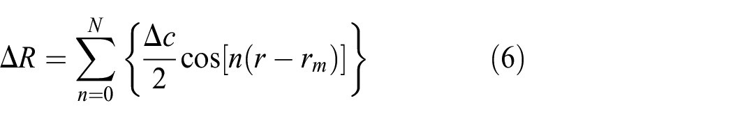
Where ΔR is known as the radius variation of cylinder liner. Δc is known as the maximum value of cylinder liner deformation. n and N are known as the deformation order and maximum deformation order. r is known as the circumferential angle, and rm is known as the angle where the maximum deformation occurs. The detailed illustration about the deformation can refer to the works of Dunaevsky. 29
Hence, the lubricant thickness in the clearance between the compression ring and cylinder liner can be expressed by:

Where ΔRmin is known as the minimum radius variation of cylinder liner. Dring is known as the complexity of compression ring, and its expression can be written as 30 :

where a is the radial thickness of compression ring. R is the radius of un-deformed cylinder liner. Ering and g are known as the elastic modulus and end gap of compression ring. pg is the backpressure acting on the inner surface of compression ring. α is the ratio between the backpressure and cylinder liner pressure, and a typical value of 0.7 is used in this study.
Pressure boundary conditions
To solve the average Reynolds equation mentioned above, the essential pressure boundary conditions must be provided. For the reciprocating compression ring, the lubricant will flow in or out of the clearance between the compression ring and cylinder liner (i.e. lubrication zone). The pressure of lubricant at the inlet and outlet of lubrication zone is given as follows:


Where xin and xout represent the inlet and outlet positions of lubrication zone, they will be discussed in the following section. pinter_ring is known as the pressure between the compression ring and oil control ring, and an atmosphere is usually adopted for it in the simulation.22,25,30pcombustor is the gas pressure in the combustor chamber.
For the rough compression ring-cylinder liner conjunction at run-time, the cavitation may occur. Generally, the cavitation contains two types. One is the cavitation occurred between the asperities on the rough surface (i.e. micro cavitation). The other is the cavitation occurred in the divergent zone of lubrication (i.e. macro cavitation). It should be noted that the micro cavitation has a small effect on the lubrication performance. Therefore, the micro cavitation between the asperities is not considered in this study. For the macro cavitation, two cavitation boundary conditions (i.e. Reynolds cavitation boundary condition and JFO (Jakobsson-Floberg-Olsson) cavitation boundary condition) are usually adopted. Compared with the Reynolds cavitation boundary condition, the JFO cavitation boundary condition takes the lubricant film reformulation into consideration, and can simulate the lubrication behaviors more reasonably. Therefore, the JFO cavitation boundary condition is used in this study.
According to the JFO theory, the lubrication zone can be divided into full film zone and cavitation zone when the lubricant is rupture, and the corresponding pressure conditions at the rupture and reformulation boundary positions can be written as 31 :

Where pc is the saturated vapor pressure of lubricant. ρ is the density of lubricant, and ρc is the density of lubricant in the full film lubrication zone.
Thermal model of lubricant
Analytical thermal equation of lubricant
At the run-time of compression ring-cylinder liner conjunction, the friction heat caused by the asperity contact under mixed lubrication regime will rise the temperature of lubricant, and consequently reduce the lubricant viscosity further or make the lubrication film difficult to form.
To simulate the lubricant temperature at run-time, two thermal models are usually used. The first thermal model is developed by solving the energy equations of lubricant and solids (i.e. compression ring and cylinder liner) numerically and iteratively. It can provide a more reasonable result, but it is time-consuming. Compared to the first numerical thermal model, the other thermal model is developed by using an analytical approach. It can also provide an acceptable and reasonable result, and more importantly, it reduced the computer time significantly. In this study, the second analytical thermal model proposed by Morris et al. 32 is applied to simulate the lubricant temperature.
It is assumed that the friction heat generated in the center of the clearance between the compression ring and cylinder liner, and will be distributed by heat conduction and heat convection (as shown in Figure 2). Hence, according to the model of Morris et al., 32 the temperature of lubricant can be simulated by:

Where Rliner, Rring, and Roil are known as the thermal resistance of cylinder liner, compression ring, and lubricant respectively. Toil, Tliner, and Tring are known as the temperatures of lubricant, liner surface, and compression ring surface respectively. Qfriction is known as the friction heat, Tinlet is the inlet temperature of lubricant, and their expressions can be written as 32 :


Distribution path of the friction heat generated in the compression ring-cylinder liner conjunction.
Lubricant rheological property
The lubricant rheological properties affect significantly the frictional performance of the compression ring-cylinder liner conjunction. Generally, the lubricant rheological properties can be described by the density and viscosity. Because the lubricant is usually known as incompressible fluid and the lubricant density fluctuates slightly in the simulation, the lubricant density variation at run-time of compression ring-cylinder liner conjunction is not considered in this study. According to the Vogel model, the dynamic viscosity variation at run-time can be reasonably described by the lubricant temperature, and the detailed relationship between the lubricant viscosity and temperature can be given as follows 33 :

where A, B, and C are Vogel parameters. Table 1 shows the lubricants with different viscosities and their corresponding Vogel parameters. The lubricant viscosity versus the temperature is depicted in Figure 3.
Lubricants with different viscosities and the corresponding Vogel parameters.

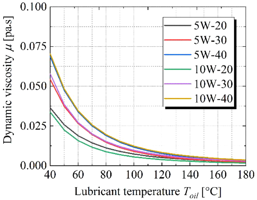
Lubricant dynamic viscosities for different temperatures.
Asperity contact model
As mentioned above, the lubrication regime of the compression ring-cylinder liner conjunction changes at run-time, and changes from the hydrodynamic lubrication regime to the mixed lubrication regime when the compression ring slides near the dead centers of piston. Under the mixed lubrication regime, the asperities on the rough surfaces of compression ring and cylinder liner will contact. For the asperity contact analysis, Greenwood-Trip and Greenwood-Williamson models are usually used in the recent researches because they are easy to implement and have good rationality. Relatively, compared to the Greenwood-Williamson model, the Greenwood-Trip model has a further improvement, and it considers the two random rough surfaces. Therefore, it is more closer to actual contact behaviors of compression ring-cylinder liner conjunction, and then it is used in this study. According to the model of Greenwood, the asperity contact force and asperity contact area can be written as 34 :


with

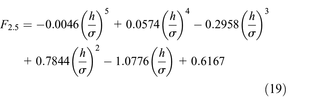

Where σβ is known as the roughness parameter, and σ/β is known as the gradient parameter of asperities. Ecomposite is the composite elastic modulus of the compression ring-cylinder liner conjunction. νring and νliner are the Poisson ratios of the compression ring and cylinder liner respectively. pasperity is the asperity contact pressure, and Aasperity is the asperity contact area.
Generally, the cylinder liner is cross-hatched/honed, and its surface asperity heights are usually not Gaussian distributed. However, based on the testing results of Gore et al., 35 after running-in period, the asperity heights of liner surface are closely to a Gaussian distribution. Therefore, the assumption of Gaussian distributed asperity heights of the liner surface is considered to be acceptable and reasonable, and adopted in the study. More realistic asperity distribution will be considered in our future research works.
Lubricant transport equation
In internal combustion engines, the compression ring acts as a sealing ring, and prevents the leakage of high-temperature gas in the combustor chamber. Hence, the lubricant supplied to the clearance between the compression ring and cylinder liner may insufficient at some crankshaft angles. This means that the assumption of fully flooded lubrication will invalid at some crankshaft angles. Therefore, it is necessary to estimate the lubrication condition (i.e. fully flooded or starved, as shown in Figure 4) dynamically according to the lubricant supplied to the compression ring.

Schematic diagram of the compression ring under different lubrication conditions: (a) starved lubrication condition and (b) fully flooded lubrication condition.
To estimate the lubrication condition of the compression ring-cylinder liner conjunction at each crankshaft angle, two control volumes are specified at the inlet and outlet of the lubrication zone. According to a mass conservative principle, 36 two mass conservative equations for the two control volume can be written as follows:


with


Where Qina and Qena are the average flow rates of lubricant that flow in and out of the front control volume. Qouta and Qexa are the average flow rates of lubricant that flow in and out of the back control volume. Qen and Qex are the flow rates of lubricant at inlet and outlet of the lubrication zone. Qfa and Qba are the average variation of flow rate of lubricant in the front and back control volume. VABCD and VWXYZ are the volumes of the front and back control volumes. hen is the thickness of lubricant that supplied to the compression ring. hf and hb are the clearance at the leading and trailing edges of the compression ring. hin and hout are the lubricant thickness at the inlet and outlet of lubrication zone. k is the factor for the control volume. The superscripted number 0 is known as the parameters at the previous moment. Figure 5 shows the diagram of the control volume.
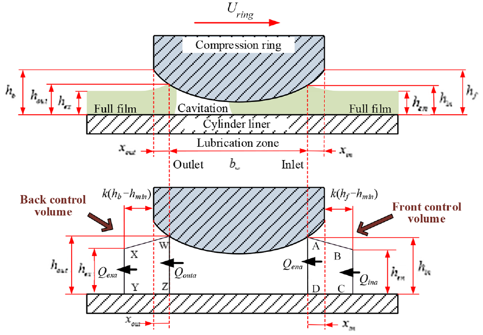
Schematic diagram of the compression ring with two control volume.
By solving the mass conservative equations, the inlet and outlet positions can be determined according to the supply of lubricant (it is depend on the lubricant left behind the oil ring). And then, the starved lubrication condition or fully flooded lubrication condition at current crankshaft angle can be recognized. More detailed discussion on the lubricant transport model can refer to the previous works. 25
Evaluation index
To evaluate the lubrication performance of the compression ring-cylinder liner conjunction, a very important parameter is the friction force. Because the mixed lubrication regime exists in the lubrication of the compression ring-cylinder liner conjunction, the friction force consists of two parts: the hydrodynamic friction force caused by the shearing stress of lubricant, and the boundary friction force caused by the asperity contact. The hydrodynamic friction force and boundary friction force can be expressed as 25 :


with

where
Hence, the total friction force, power loss, and friction loss (i.e. FMEP) can be calculated by the following expressions 33 :


Where ftotal is the total friction generated between the compression ring and cylinder liner. Wpower_loss and FMEP is the power loss and friction loss respectively. Vcombustor is the single-cylinder displacement of the engine.
Furthermore, the wear load on the compression ring surface is also simulated, and its expression is as follows 33 :
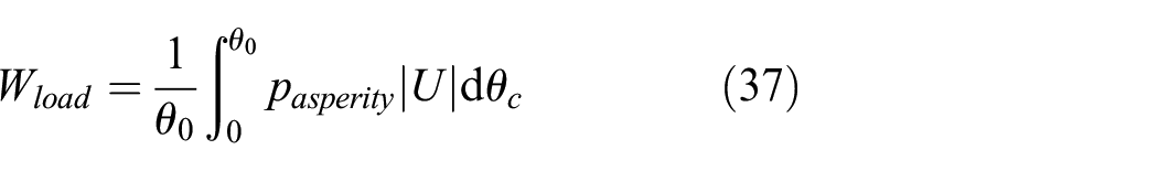
where θc is the crankshaft angle, θ0 is 720° for a four-stroke engine.
Results and discussion
Before solving the model, the model should be verified. In our previous research work, 37 the main part of the model is verified by comparing with the reported work of Gu et al., 38 and the results calculated by our model is consistence with the results calculated by the work of Gu et al. This indicates that the model in this study can be used to analyze the frictional performance of the compression ring.
For the model, the average Reynolds equation with modified factors and JFO boundary conditions is solved by the finite difference method, and the convergence criteria of the hydrodynamic pressure of oil film is 1e-5. After solving the hydrodynamic pressure of oil film, the force balance equation of compression ring in radial direction (i.e. the difference among the external load, oil film pressure, and asperity contact pressure is equal to the inertia force of compression ring) is solved to obtain the minimum oil film thickness, and the convergence criteria of the force balance is 1e-4.
Furthermore, 0.1 crank angle is adopted as time step of solution in this study to achieve the convergence.
Based on the numerical model mentioned above, the friction force, power loss, MLT, and friction loss of the compression ring-cylinder liner conjunction can be simulated for the lubricant with different viscosities. In the simulation, the engine speed is 2000 rpm, and the corresponding cylinder pressure and the relative slide speed of the compression ring are shown in Figure 6. The parameters of the compression ring-cylinder liner conjunction used in the simulation are provided in the Table 2. It should be noted that only one-fourth cylinder liner is considered as the simulation zone because the cylinder liner with 4th order deformation is axisymmetric.

Cylinder pressure and relative speed of compression ring for the engine speed 2000 rpm.
Parameters of the compression ring-cylinder liner conjunction used in the simulation.
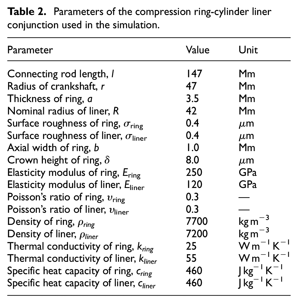
Figure 7 depicts the results of MLT for different lubricants. In Figure 7, the difference of MLT among different lubricants is significant, especially when the compression ring slides near the middle of the compression and power strokes (i.e. the crankshaft angle is from 180° to 540°). Furthermore, when the compression ring operates at the dead centers of the stroke (i.e. the crankshaft angle is 360° and 540°), the ratio of minimum lubricant thickness to the composite roughness less than 4, the lubrication condition is regarded as mixed condition, and the difference of MLT among different lubricants is really small. By comparing with the lubricant of 5W-20, the MLT is relatively small for the lubricant of 10W-20. However, a reverse trend is observed for the lubricants of 5W-30 & 10W-30 and 5W-40 & 10W-40 (i.e. the MLT for the lubricant of 5W-30 is smaller than the lubricant of 10W-30, and the MLT for the lubricant of 5W-40 is also smaller than the lubricant of 10W-40). This is because that the lubricants of 5W-30 and 5W-40 have small dynamic viscosities.

MLT between the compression ring and cylinder liner for different viscosities of lubricant.
In actuality, the compression ring is usually under starve condition because of the lubrication control effect of oil ring. Therefore, the minimum oil film thickness under fully flooded condition is not analyzed in this manuscript. When the compression ring is under starved condition, the minimum oil film thickness is usually less than the minimum oil film thickness for the ring under fully flooded condition, the interesting readers can refer the previous study. 25
The hydrodynamic friction force and asperity friction force between the compression ring and cylinder liner are shown in Figure 8 for different lubricants. It can be seen from Figure 8(a) that the lubricant viscosity has a great influence on the hydrodynamic friction force. Compared with the hydrodynamic friction force at the dead centers, the difference of hydrodynamic friction forces is large when the compression ring-cylinder liner conjunction at the middle of the intake, compression, power, and exhaust strokes (i.e. the crankshaft angle is 90°, 270°, 450°, and 630°). This is because that the slide speed of compression ring is high at the middle of the strokes. Relatively, the lubricant of 10W-20 has small hydrodynamic friction force because of its low viscosity. From Figure 8(b), it can be seen that the lubrication regime of the compression ring-cylinder liner conjunction is mixed when the crankshaft angles are about 360° (i.e. the top dead center of the power stroke) and 540° (i.e. the bottom dead center of the power stroke). Furthermore, in a reversal of the trend of hydrodynamic friction force, the lubricant of 10W-20 shows larger asperity friction force than the other lubricants. The reason is that the low viscosity of lubricant of 10W-20 results in a low load-carrying capacity and a relatively small clearance between the compression ring and cylinder liner, and consequently causes a significant asperity contact behavior on the rough surfaces of compression ring and cylinder liner.

Hydrodynamic friction and asperity friction forces between the compression ring and cylinder liner for different viscosities of lubricant: (a) hydrodynamic friction and (b) asperity friction.
To recognize the lubrication condition (i.e. fully flooded lubrication condition or starved lubrication condition) of the compression ring-cylinder liner conjunction, the inlet positions of lubrication zone for different lubricants are simulated. The simulated results are shown in Figure 9. It can be seen from Figure 9 that the inlet position value is equal to zero when the crankshaft angle is change from 360° to 540°. This result means that the leading edge of the compression ring is fully flooded when the compression ring operates on the power strokes. This is because that the clearance between the compression ring and cylinder liner is small, and consequently the lubricant supplied to the clearance is enough to cover the leading edge of the compression ring. Moreover, the inlet position value is greater than zero at the middle of the intake, compression, and exhaust strokes, and the lubricant of 10W-40 has larger value of inlet position than the other lubricants. This indicates that the lubrication condition of the conjunction at the middle of the intake, compression, and exhaust strokes is starved, and the degree of starve for the lubricant of 10W-40 is worse than the other lubricants.
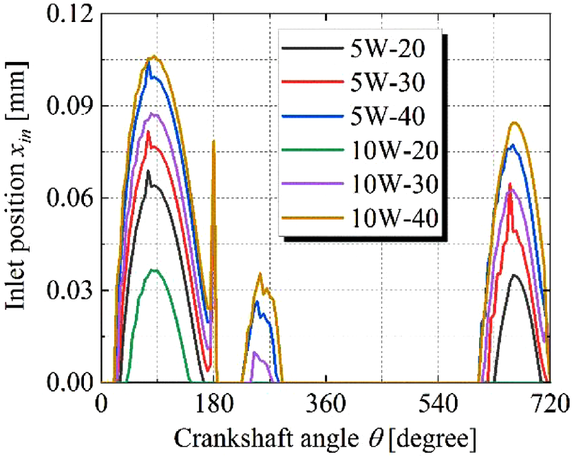
Inlet positions of lubrication zone for different viscosities of lubricant.
Moreover, it can be also seen that the lubricant of 10W-20 has minimum inlet position value and the range of crank angle is large for the zero inlet position value. This indicates that the lubricant with low viscosity is more beneficial to facilitate the change of lubrication condition from starve to fully flooded.
Figure 10 shows the power loss of the compression ring-cylinder liner conjunction caused by the hydrodynamic friction force and asperity friction force for different lubricants. In Figure 10(a), similar with the results of the hydrodynamic friction force, the lubricants also show a significant influence on the power loss caused by the hydrodynamic friction force, especially when the relative slide speed of compression ring is large (i.e. middle of the strokes). From Figure 10(b), it can be seen that the power loss caused by the asperity friction force mainly exists at the dead centers of the power stroke. And the lubricant of 10W-20 shows large power loss caused by the asperity friction force.
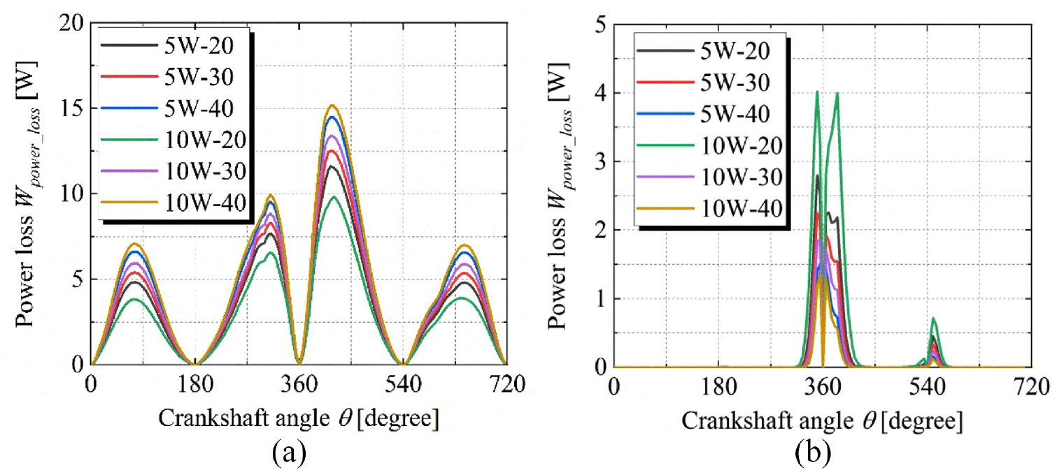
Power loss caused by hydrodynamic friction and asperity friction forces for different viscosities of lubricant: (a) power loss caused by hydrodynamic friction and (b) power loss caused by asperity friction.
To simulate the wear of the compression ring-cylinder liner conjunction, Figure 11 shows the wear load acting on the surface of compression ring for different lubricants. It can be observed that lubricant viscosity has a great influence on the wear load on the compression ring surface. This means that the wear degree of compression ring-cylinder liner conjunction has close relation with the lubricant viscosity. In details, it can be seen from Figure 11 that the maximum wear load is observed for the lubricant of 10W-20. This indicates that the lubricant with low viscosity may result in large wear. Furthermore, the maximum wear load is mainly occurs at the middle of the compression ring in the axial direction. This is because the clearance between the compression ring and cylinder liner is minimum at the middle of the compression ring in the axial direction.

Wear load on the compression ring surface for different lubricants: (a) lubricant of 5W-20, (b) lubricant of 5W-30, (c) lubricant of 5W-40, (d) lubricant of 10W-20, (e) lubricant of 10W-30, and (f) lubricant of 10W-40.
The FMEP is also calculated for the compression ring-cylinder liner conjunction for different lubricants to evaluate the friction loss. The results of FMEP for different lubricants are shown in Table 3. In Table 3, different FMEP values are observed for different lubricants. This indicates that the influence of lubricant viscosity on the friction loss of the compression ring-cylinder liner conjunction is significant. Specially, for the lubricants in this study, the lubricant 10W-20 has small friction loss because of its low friction and viscosity. This result also shows that the lubricant with low viscosity has potential to reduce the friction power loss of the compression ring-cylinder liner conjunction.
FMEP values of the compression ring-cylinder liner conjunction for different lubricants.

In this manuscript, we mainly focused on the effects of lubricant viscosity on the frictional performance, the effect of starved and fully flooded lubrication conditions on the frictional performance is discussed in details in our previous studies. 25
Conclusions
In this study, an improved mixed lubrication model is developed for the compression ring-cylinder liner conjunction with considerations of the cylinder liner deformation, the lubricant thermal effect & transportation, and the change of lubrication condition from full flooded to starve. And then, the influence of the lubricant viscosity on the frictional properties of the conjunction is investigated. The main conclusions are as follows:
The lubricant viscosity has significant influence on the MLT, friction force, power loss, and inlet lubrication condition of the compression ring-cylinder liner conjunction, especially at the middle of the strokes. Generally, the lubricant with low viscosity will obtain low friction, MLT, and power loss. Furthermore, the lubricant with low viscosity is also more beneficial to facilitate the change of lubrication condition from starve to fully flooded. However, it should be noticed that the lubricant with low viscosity also results in higher wear load on the compression ring surface. It means that the compression ring-cylinder liner conjunction is more prone to wear if low viscosity lubricant is used.
It should be noted that the dynamic motion of the compression ring is not considered in this study, and it will be the direction of our further study. Furthermore, the effect of starved and fully flooded lubrication conditions on the frictional performance for different viscosity lubricant will be also discussed in our future works
Footnotes
Handling Editor: Chenhui Liang
Declaration of conflicting interests
The author(s) declared no potential conflicts of interest with respect to the research, authorship, and/or publication of this article.
Funding
The author(s) disclosed receipt of the following financial support for the research, authorship, and/or publication of this article: This work was supported by National Natural Science Foundation of China (No. 52075438), Research Program of Weinan of Shaanxi Province of China (No. STYKJ2022-5), Science and technology innovation team project of Shaanxi Railway Institute (No. KJTD202101).