
Abstract
Thermal effects on fatigue life were investigated by analyzing the thermomechanical behavior of double-row tapered roller bearings (DTRBs) and a fatigue life prediction model was developed. A bearing’s mechanical behavior was analyzed using a quasi-static model and its thermal behavior was analyzed using a thermal network method. Viscous drag and sliding friction at the contact area were considered as heat generation factors for DTRBs. The bearing lubrication characteristics and shape dimensions interacted with the temperature and the analysis was repeated until the entire DTRB system’s temperature converged. DTRB fatigue life was estimated using a fatigue life formula based on Gupta and Zaretsky’s statistical model. Results confirmed that the fatigue life decreased rapidly because of an interference fit that occurred at very high rotation speeds or at very low supply oil flow rates. This interference fit phenomenon is caused by thermal expansion of the bearing element. The interference fit can be prevented by designing with a large initial clearance value, but an initial clearance that is too large affects fatigue life negatively because of load distribution imbalance. Optimal design of the roller end sphere radius to minimize sliding friction for the flange part can provide additional help in preventing interference fit.
Keywords
Introduction
Rolling bearings are essential mechanical elements that provide support and power transmission while maintaining the rotational motion between two mechanical elements, and are frequently subjected to harsh operating conditions, including high stresses and high rotational speeds. The harshness of these operating conditions has been highlighted continuously in recent years as higher operating speeds and weight reduction of the mechanical parts have been achieved. Additionally, the performance of rolling bearings should be secured and the bearing lifespan should be extended. Rolling contact fatigue (RCF), which is an important factor that limits the performance and lifetime of rolling bearings, has become the most important failure mechanism for these bearings over the past few decades. RCF studies have been developed by numerous researchers,1,2 despite the assumptions required for appropriate mounting and lubrication. In addition, the severe operating conditions cause the temperature of the rolling bearings to increase along with increasing RCF. Recently, research into the thermal behavior of rolling bearings has been increasing rapidly. 3 In particular, because the thermal deformation of bearing elements caused by a temperature increase changes the pressure between the raceways and the rolling elements significantly, even with low thermal expansion, clear identification of the effects of thermal behavior on the performance of rolling bearings is now a very important research topic.
The double-row tapered roller bearing (DTRB), which is a type of rolling bearing, is widely used in helicopter gearboxes, gas turbine engines, railways, and other applications because DTRBs can transmit severe load conditions, particularly in the case of very large axial and radial loads. Because of this increasing demand for DTRBs, many researchers have studied the mechanical or thermal behavior of these bearings.4–7 The mechanical behavior of the DTRB is generally analyzed as a load distribution based on a quasi-static model and is an important factor when calculating the bearing fatigue life and the heat generation value. Harris 8 established a quasi-static basic model of rolling bearings and then calculated their load distribution. Andreason 9 calculated the load distributions of tapered roller bearings (TRBs) using vector analysis and slicing methods and predicted the rated life of these bearings. Nelias et al. 10 established a quasi-static model by considering the skewing of the rolling elements in a TRB and also calculated the skewing values according to the speed, misalignment, and shape dimensions of the TRB. The mechanical behavior of single-row TRBs has been improved through the efforts of several other researchers.11,12 However, because DTRBs are structures in which two single-row tapered roller bearings are assembled, a different model is required for DTRB analysis. Bercea et al. 13 introduced vector analysis and slicing methods and then calculated the load distribution of a DTRB by considering the five degrees of freedom of the inner raceway and the three degrees of freedom of the roller. Luo and Luo 14 developed a model that provided excellent convergence without using the individual equilibrium equation for each roller and considering only the three degrees of freedom of the DTRB; however, it was difficult to confirm the mechanical properties of DTRBs at high speeds using this model because it did not consider the centrifugal force. Yang et al. 4 improved on the model proposed by Luo and Luo 14 by considering both the centrifugal force and the angular misalignment and studied the load distribution characteristics of the DTRB while considering the rotational speed, the load, and the angular misalignment. In the model in this paper, the mechanical behavior of the DTRB was analyzed by applying the model of Yang et al., 4 which consisted of three degrees of freedom, and modifying it to have five degrees of freedom.
Thermal network models and finite element models (FEMs) are used widely to investigate thermal effects in rolling bearing systems. Thermal network models are primarily used to analyze the thermal behavior of complex systems because they offer faster analysis times and better convergence than FEMs. Pouly et al.15,16 built a thermal network model of a lubricant/air-lubricated rolling bearing and calculated the temperature increase based on the heat source location and the lubricant–air ratio. Ai et al. 5 established a thermal network model of a DTRB and investigated the effect of the roller end sphere radius on the thermal behavior under grease lubrication conditions. However, they investigated the steady-state temperature distribution only, and the coupling effect of the thermal expansion caused by the temperature increase in the structure, which would affect the load distribution, was not considered. Ma et al. 17 established a transient thermal network model of a spherical roller bearing lubricated with grease. Zheng et al.18–20 constructed a thermal network model that considered the thermal expansion of an angular contact ball bearing and compared their model’s results with experimental results; they concluded that the difference between the model values and the experimental values decreased as their thermal network model became increasingly sophisticated. Hao et al. 21 established a thermal network model for cylindrical roller bearings and proposed a thermal–fluid–solid coupling model in which a temperature increase affects both the lubricant and the bearing structure. Their thermal–fluid–solid coupling model showed better agreement with the experimental results than the existing thermal model, which did not consider the coupling effect. Although many other researchers have conducted studies that considered the mechanical and thermal behaviors of rolling bearings, or indeed considered both behaviors simultaneously, studies that analyzed the effects of the reduction in clearance caused by thermal expansion on the thermomechanical behavior of DTRBs are difficult to find. In addition, no quantitative analysis of the influence of this effect on the fatigue life, which is the most important aspect of the performance of rolling bearings, has been conducted to date. Therefore, this study has investigated the fatigue life change based on the thermal effects on DTRBs by considering the interacting thermomechanical behavior.
In this study, thermal effects on the fatigue life of DTRBs were analyzed by developing a model to analyze the thermomechanical behavior and the fatigue life of the DTRB system. The DTRB load distribution was calculated using a quasi-static model analysis. In addition, to investigate the DTRB system’s thermal behavior, a transient thermal network model that included a cooling device, the sliding friction of the contact area, and viscous drag heat generation was used. After the thermal network model analysis, the load distribution was recalculated by considering the clearance changes caused by the thermal expansion of each element, and this process was repeated until the temperature of the entire DTRB system converged. The DTRB’s fatigue life was estimated using the statistical model of Gupta and Zaretsky. 22 The analysis results demonstrated the effects of the operating conditions, e.g. the rotational speed and the supply oil flow rate, and the design dimensions, e.g., the initial clearance and the radius of the roller end sphere, on the thermomechanical behavior and the fatigue life of the DTRB.
Theoretical analysis
DTRB load distribution with thermal expansion
Figure 1 shows a cross-section of the DTRB that considers the internal clearance


Cross-section of the DTRB.
The DTRB has an asymmetric load along each row because of the axial load, which causes an asymmetric clearance. The subscript
where
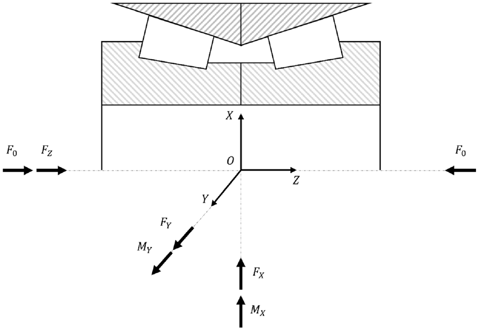
DTRB external load condition and coordinate system.

Displacement of an inner raceway (where the outer raceway is fixed) due to the application of combined radial, axial, and moment loadings.
Based on the radial and axial displacements when the effects of the bearing’s angular displacement are considered, the linear displacement of the roller can be obtained as follows:


where

where
Subsequently, if the roller displacement is converted into the vertical displacement of the outer raceway–roller contact, the contact force can then be obtained using the load–displacement relation.


where

where
The normal contact force acting on the outer raceway can be decomposed into components based on the coordinates of the bearing system and can be expressed as follows:


where
The moment caused by the contact force can be expressed as follows.


The contact force of the DTRB outer raceway can be obtained based on the sum of the internal load and the moment applied to the outer raceway, the equilibrium condition with the external load and the moment, and the equilibrium equation of the outer raceway, as follows:


where the subscript
When the DTRB outer raceway contact force has been obtained, the inner raceway and flange contact forces can then be obtained by substituting the outer raceway contact force into the equilibrium equation for the roller. The equilibrium equation for each roller is:

where
Heat generation and heat transfer of the DTRB
Heat generation of the DTRB
The rolling friction power loss in roller bearings is generally small when compared with the other sources of power loss and is thus neglected. 21 Therefore, only the sliding friction power loss and the viscous drag power loss are considered in the DTRB model presented here.
Sliding friction heat generation of the DTRB
The sliding friction heat generation that occurs between the roller and the raceway can be obtained by integrating the lubricant shear stress and the relative sliding speed over the contact area. 8

where


where
The shear rate can be approximated as follows by assuming that the oil film thickness on the contact surface remains constant at the central oil film thickness. In addition, in the DTRB, the raceway–rolling element contact is a line contact, but the large roller end with a radius of


The viscosity is considered as a function of both pressure and temperature using the Houpert equation: 26


where
A method to calculate the contact area relative to the sliding speed
Viscous drag heat generation of the DTRB
When the roller rotates around the shaft between the lubricants, heat is generated because of the viscous drag. 27
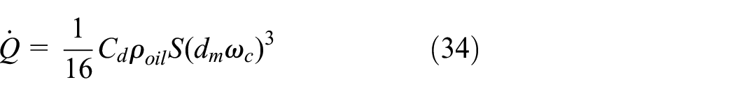
where
Heat transfer of the DTRB
A thermal network model was selected to perform the thermal analysis of the rolling bearing system. The heat generated in the DTRB is transferred by both conduction and convection. In the thermal analysis of rolling bearings, the effect of thermal radiation is generally negligible; therefore, it is ignored in this model.21,18
Thermal conduction resistance of the DTRB
The axial heat conduction resistance of cylinders such as raceways, housings, shafts, and rollers is defined as: 28
where
The radial thermal resistance of hollow cylinders such as raceways, housings, and shafts is defined as: 28

where
The radial thermal resistance of a cylinder such as a roller is: 28
The contact resistance caused by the presence of the contact force can be expressed by considering the size and the movement of the Hertz contact, as follows: 29


where
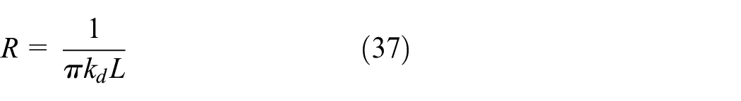
Thermal convection resistance of the DTRB
In a DTRB system, heat is transferred first to the lubricant and subsequently to each bearing element. The heat is then transferred to the surrounding air, and this process can be expressed as convective heat transfer in the thermal network model. The convection thermal resistance is expressed as a function of the Nusselt number

Convection with the outside air occurs on the inner surface of the hollow shaft. In this case, the Nusselt number is given by: 31

where
Natural convection occurs between the outer surface of the housing side and the surrounding air. In this case, the Nusselt number is given by: 32
Convection occurs between the sides of the rotating shaft and the outside air. In this case, the Nusselt number is given by: 33

where
Natural convection also occurs between the front outer surface of the housing and the surrounding air, which can be simplified by regarding it to be natural convection in parallel plates. Here, the Nusselt number is: 34
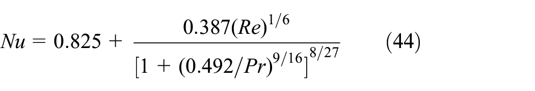
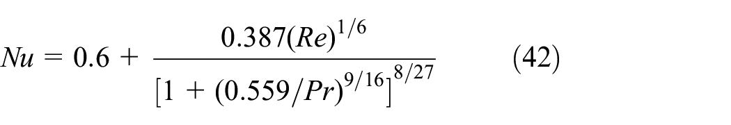
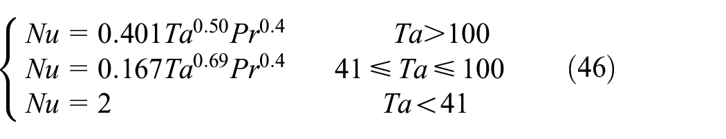
Convective heat transfer occurs when the rollers move between the lubricants. The Nusselt number in this case is: 35

The outer and inner raceways are cylindrical and the space between these raceways is filled with the lubricating oil during operation. Here, the raceways can be simplified to be a concentric rotating cylindrical model, and the Nusselt number between the surface of the raceway and the lubricant is expressed as follows: 30
where
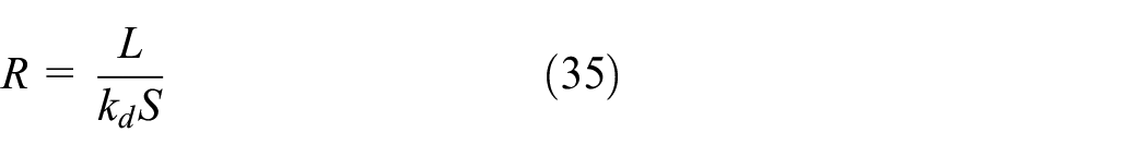
The lubricating oil supplied inside the bearing absorbs the heat and is then discharged to the outside. The thermal resistance to the supply and discharge of the lubricant is given by: 15

where
Thermal network model of the DTRB
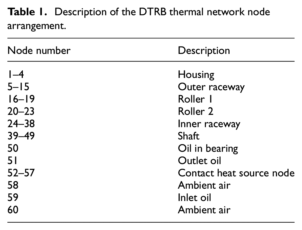
Thermal network node planning
After the bearing structure has been simplified, the thermal network node can be divided into several thermal nodes (see Figure 4). As the number of nodes in the thermal network model increases, the accuracy of the analysis improves but the computational cost increases.
18
According to Zheng and Chen,
18
multi-node models provide the most accurate analytical values. Therefore, the analysis model in this work was set up as a thermal network model with 62 nodes based on a multi-node model. Each node is connected via conduction or convective thermal resistance. The red dots shown in Figure 4 indicate the heat sources of the DTRB;

Thermal network model of the DTRB.
Description of the DTRB thermal network node arrangement.

Conductive and convective heat resistance relationships between the DTRB elements.
Establishing the thermal equation
The transient temperature calculation for the thermal network method is based on the fact that the heat flux for a node is equal to the increment in its internal energy. When node

where
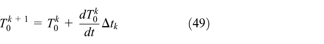
where

Application of the equation above to the DTRB thermal network model allows a set of transient thermal analysis equations to be obtained for all nodes. These equations can be expressed as determinants and are then solved via Gaussian elimination.

Configuration of the heat transfer model for node 0.
Figure 7 shows an overall flow chart for the analysis model. First, a quasi-static analysis is performed based on the operating conditions, including the external load, the inner raceway rotation speed, and the supply oil flow rate. The mechanical properties of the DTRB that were obtained through quasi-static analysis are then used to determine the heat generation, conduction, and convective thermal resistance. The DTRB’s temperature distribution can be obtained by analyzing the thermal network model of the DTRB. Subsequently, the internal clearance of the bearing can be corrected by calculating the thermal deformation of each element caused by the temperature increase in the DTRB element. Additionally, the viscosity of the lubricant and the film thickness can both be modified by considering the temperature of the lubricant inside the bearing. This analysis is repeated until the convergence condition shown in Figure 7 is reached.

Flowchart for the DTRB thermomechanical analysis.
Fatigue life of the DTRB
The main failure mechanism of rolling bearings is rolling contact fatigue and the LP model presented by Lundberg and Palmgren is currently the most widely used model for bearing lifetime prediction.36,37 Gupta and Zaretsky 22 subsequently removed the relationship between the lifetime and the stress depth from the LP model and changed the critical failure stress into the subsurface shear stress. The lifetime coefficient for the shear stress in the life equation was the variability of the test data, or the Weibull constant was improved such that it was independent of the fatigue life equation.

where
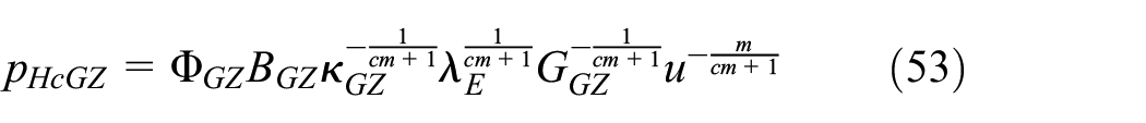
The equation for the Gupta-Zaretsky (GZ) fatigue life of the raceway in line contact is expressed as follows:

Here, the dynamic stress capacity


Similar to the approach for the raceway, the GZ fatigue life equation for the roller can be expressed as follows:
The dynamic stress capacity of the roller and its related parameters are then expressed as follows.


All other parameters are the same as those used for the raceway.
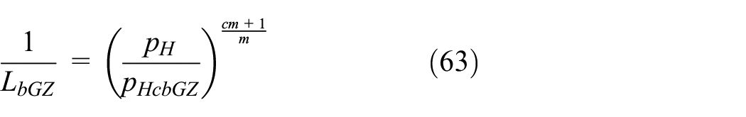
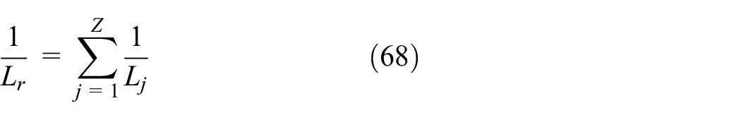
The life equations above provide an estimate of the lifetime at each contact for the bearing. To calculate the lifetime for the entire bearing, the lifespans for each contact must be summed statistically. For a fixed race in which only one of the raceways rotates within the bearing, each contact is independent of the others; therefore, the service life of the fixed raceway

For a rotating raceway, the same load variation is applied periodically at each contact point. Therefore, the lifespan of the rotating raceway
For a rotating roller, the service life of the roller

The life equation for the entire bearing, which statistically sums up the fatigue lives for the raceways and the balls, can be expressed as follows:

where the subscript
When analyzing the fatigue lifetimes in this study, the fatigue lifetime results for the American Iron and Steel Institute (AISI) 52100 material used in the GZ study were used, and all important values required for this analysis are listed in Table 2. It was assumed that the material properties used in the lifetime equation are independent of temperature.
Estimated model constants derived from experimental life data.

Results and Discussion
To verify the DTRB load analysis of this model, the results from Nélias et al. 38 were compared with those obtained using the current model without consideration of the thermal effect. The bearing structure parameters for the analysis were obtained from the analysis model of Nélias et al. 38 Table 3 compares the displacements of the inner raceway under the various radial and axial loading conditions of Nélias et al. 38 and the proposed model. Nélias et al. 38 provided a complex vector analysis-based model that considers the displacement of each rolling element, and the model proposed here considers only the displacement of the inner raceway to ensure numerical convergence. However, these two models showed very good agreement, with a maximum difference of approximately 5.37%.

The fatigue life prediction results of the current analysis model are affected significantly by the contact pressure; therefore, the results may vary significantly depending on the external load. In this study, to check the effects of the operating speed, the supply oil flow rate, and the DTRB’s precision design parameters on the fatigue life rather than the external load, the external load states were:
Parameters of double-row tapered roller bearing.

Lubricant parameters.
Figure 8 shows the load distributions of the DTRB when the thermal effect is not considered under a given load condition at a rotational speed of 6 kr/min. When an axial load is applied to one side, the load in row 1 of the DTRB is generally higher than that in row 2. This causes asymmetry of the contact pressure and the clearance that is dependent on the heat of the DTRB. Therefore, the results are considered to be the clearance, the film thickness, and the maximum contact pressure in row 1 under a high load under the current conditions.

Contact loads of the DTRB. (a) Contact load of roller–outer raceway; (b) contact load of roller–inner raceway; (c) contact load of roller–flange.
Thermal analysis of the DTRB
The heat sources of the DTRB result from a combination of the sliding friction at the contact area and viscous drag. Figure 9 shows the heat generation results for the DTRB heat sources versus the rotation speed when the supply oil flow rate was fixed at

Heat generation of the DTRB for various inner-raceway rotational speeds.
To verify the effects of the rotational speed and the supply oil flow rate on the temperature of the DTRB, Figure 10 shows the temperature at each node in the thermal network model. The supply oil flow rates were 60 and 180 cc/min, the rotation speeds were 2 and 8 kr/min, and results for a total of four cases were obtained. Figure 9 shows that the increase observed in the DTRB temperature distribution was insignificant at low speeds because of the low heat generation value. However, at higher speeds, the amount of heat generated increased rapidly, the temperature increased significantly, and the temperature differences between the nodes also increased. Greater supply oil flow rates produced a greater cooling effect that absorbed the heat through a forced convection heat transfer process and then discharged it from the bearing, thereby lowering the overall DTRB system temperature. At each node, the temperature difference relative to the supply oil flow rate was insignificant at low speeds at approximately 2.5%, whereas the temperature difference relative to the supply oil flow rate under the high-speed condition was approximately 49.5%. These results indicate that the cooling effect of the supply oil flow rate played a major role under the high-speed condition, where large-scale heat generation occurred relative to that at the low-speed condition.

Node temperatures of the DTRB for various inner-raceway rotational speeds and supply oil flow rates.
Effect of operating conditions on fatigue life of the DTRB
Figure 11 shows the fatigue life characteristics of the DTRB versus the rotation speed at various supply oil flow rates when the initial clearance was fixed at

DTRB fatigue life predictions vs. inner-raceway rotational speed at various supply oil flow rates.

(a) DTRB clearance and (b) maximum Hertzian contact pressure vs. inner-raceway rotational speed at various supply oil flow rates.
Effect of precision design parameters on the DTRB fatigue life
The precise design parameters that were considered in this study were the initial clearance and the radius of the roller end sphere. When the thermal effects are considered, these variables interact and can change the fatigue life of a DTRB significantly within a given operating environment. Therefore, in this section, the effects of the initial clearance and the roller tip radius on the thermal behavior and the fatigue life of the DTRB are analyzed.
Effect of initial clearance
Figure 13 shows the effect of the initial clearance of the DTRB on the fatigue life. The rotation speeds were set at
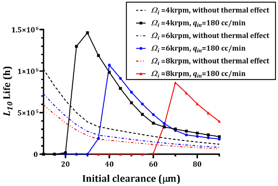
Predicted fatigue life vs. initial clearance at various inner-raceway rotational speeds.
Effect of the roller end sphere radius
The main cause of fatigue life reduction in the current analysis model is the interference fit of the DTRB caused by high heat generation. Therefore, minimization of the heat generation value is an important factor in the DTRB fatigue life. As shown in Figure 9, the viscous drag-based heat generation accounts for the largest proportion of the heat generation in the DTRB. However, viscous drag-based heat generation is dependent on the rotation speed, the lubricating oil’s properties, and the roller surface area, and thus has only slight relevance to the precision design parameters. Additionally, the radius of the roller end sphere that is in contact with the flange of the inner raceway has slight effects on both the load volume and the volume of the DTRB; therefore, this radius can be regarded as a useful design factor for reduction of the amount of heat being generated. Flange sliding friction-based heat generation is affected by the oil film thickness and the relative speed of the contact area, and is also significantly affected by the roller end sphere radius. Therefore, in this section, the effect of the roller end sphere radius on the fatigue life and the heat generation value is discussed. Figure 14 shows the fatigue life versus the roller end sphere radius at various initial clearances. The radius of the roller end sphere was varied from 120 to 360 mm. To check the effect of the roller end sphere radius under different conditions, we set initial clearance values of 25, 30, 40, and 50 μm, while the supply oil flow rate and the rotation speed were fixed at 200 cc/min and 6 kr/min, respectively. When the initial clearances were 40 and 50 μm, the fatigue life changes were insignificant because no additional contact force was generated because of the interference fit under the corresponding operating conditions. In addition, the fatigue life was generally higher at 40 μm than at the initial clearance of 50 μm. This was because, as explained in the previous section, when the interference fit did not occur, a smaller clearance produced a more evenly distributed load. When the initial clearance was 30 μm, the fatigue life decreased sharply because of the interference fit over the entire radius of the roller end-sphere, and the fatigue life showed a maximum value when the roller end-sphere radius was approximately 200 mm. In the other sections, the fatigue life exhibited a large gradient and decreased. When the initial clearance was 25 μm, the same tendency was also shown, and the overall fatigue life was reduced because of the larger interference fit effect. The DTRB fatigue life relative to the roller end sphere radius and the initial clearance was analyzed in terms of the sliding friction-based heat generation and the clearance. As shown in equation (29), an increase in the central oil film thickness reduced the sliding friction-based heat generation, whereas an increase in the sliding speed caused the sliding friction-based heat generation to increase. To investigate this behavior in more detail, Figure 15(a) shows the sliding speed and the central oil film thickness characteristics for two cases: with an initial clearance of 30 μm and an interference fit, and with an initial clearance of 50 μm but without the interference fit. The central oil film thickness increased as the roller end sphere radius increased, and the thickness at the initial clearance of 30 μm was generally lower than that for the initial clearance of 50 μm because of the increase in the contact force caused by the interference fit. The sliding speed showed almost no difference relative to the initial clearance, and in both cases, the speed decreased gradually as the radius of the roller end sphere increased before subsequently increasing rapidly from a radius of 210 mm. Figure 15(b) shows the tendency for the sliding friction-based heat generation with a minimum value at a specific speed when these two factors were combined. The clearance took the form of a maximum value at the roller end sphere radius of 210 mm (see Figure 15(c)). This was the opposite trend to the frictional heating case, and it can be interpreted as the effect of reduction of the clearance due to sliding friction-based heat generation. In particular, for an initial clearance of 30 μm, at which the interference fit occurred, a greater negative clearance due to heat generation led to greater contact pressure being caused by the interference fit (Figure 15(d)), and the fatigue life thus decreased. Therefore, the maximum fatigue life occurred when the clearance was at its largest, i.e., at the radius of the roller end sphere with the lowest negative clearance. However, as mentioned above, when the initial clearance was 40 or 50 μm, the negative clearance was not sufficient to cause an interference fit. Therefore, almost no change occurred in the contact pressure relative to the roller end sphere radius in these cases, and the change in the fatigue life was also insignificant as a consequence.

Predicted fatigue life vs. roller end sphere radius characteristics at various initial clearances.

(a) Central film thickness and relative sliding speeds, (b) flange–roller sliding friction heat generation, and (c) DTRB clearance for various initial clearances and roller end sphere radius values. (d) Maximum Hertzian contact pressure.
The previous section confirmed that there was an optimal initial clearance and optimal roller end sphere radius where a minimum amount of heat was generated under given operating conditions. Generally, a smaller initial clearance is better, but if the clearance is exceedingly small, then an interference fit may occur. Therefore, if the thermal effect is considered, the precision design parameters for the DTRB should be designed by considering their close interactions with each other.
Conclusion
In this study, the thermal effect on the fatigue life of DTRBs was investigated by analyzing the thermomechanical behavior of these DTRBs and developing a fatigue life prediction model. The main cause of the thermal effect that affects the fatigue life is the clearance change that occurs because of thermal expansion. The conclusions that were drawn from this study are given as follows.
(1) When the rotational speed is very high or the supply flow rate is very low, the fatigue life of the DTRB may decrease rapidly. This occurs because the cooling effect of the supply oil flow rate is insufficient in this case, which results in an interference fit being caused by the thermal expansion of the DTRB.
(2) The initial clearance can compensate for the thermal expansion of the DTRB. Under low-speed conditions, where the thermal expansion does not occur on a significant level, a large initial clearance adversely affects the fatigue life because it causes an imbalance in the load distribution. However, under high-speed conditions where greater thermal expansion occurs, the initial clearance of the DTRB should be set to be larger to compensate for the thermal expansion.
(3) The sliding friction of the flange part, which is the main cause of the high heat generation factor of the DTRB, can be minimized by adjusting the radius of the roller end sphere. The reason for this effect is that the oil film thickness and the sliding speed of the flange part are both affected by the roller end sphere radius. In addition, the occurrence of the interference fit has a significant effect on the flange’s sliding friction, and the main cause of this phenomenon is the reduction in the oil film thickness caused by the rapid increase in the contact force.
Although the fatigue life equation used in this study had already been verified by Gupta and Zaretsky, the main limitation of this study is that the results of the fatigue life analysis with consideration of the thermal effect were not verified experimentally. Therefore, our follow-up study will focus on the experimental validation of this fatigue life prediction model.
Footnotes
Handling Editor: Chenhui Liang
Declaration of conflicting interests
The author(s) declared no potential conflicts of interest with respect to the research, authorship, and/or publication of this article.
Funding
The author(s) disclosed receipt of the following financial support for the research, authorship, and/or publication of this article: This work was supported by the National Research Foundation of Korea (NRF) grant funded by the Korean government (MSIT) (No. 2022R1C1C2003523) and by the Basic Science Research Program through the National Research Foundation of Korea (NRF) funded by the Ministry of Education (No. 2021R1I1A3060132).