
Abstract
Cutterhead is the key component of the mega shaft boring machine (SBM), whose complex structure and huge size lead to high manufacturing difficulty and cost, and its reliability is difficult to guarantee under huge loads. It is difficult to design the cutterhead only referring to the existing small horizontal tunnel boring machine cutterhead. In order to brainstorm innovative ideas, the paper incorporates the TRIZ into AD to address the following issues. Firstly, engineering conflicts in designing process are eliminated by TRIZ tools to generating innovative ideas. Then, the decomposition of functional requirements and design parameters are employed based on independence axiom of AD, transferring the abstract ideas into concrete design solutions. Moreover, fuzzy comprehensive evaluation is adopted to choose a better design scheme from alternatives of critical component. Finally, the feasibility and practicality of the proposed approach has been demonstrated through case study of designing a novel mega SBM cutterhead. The cutterhead structure is significantly improved with embedded movable cutter boxes, which can excavate step by step to reduce the driving torque, and the manufacturing and transportation cost has been greatly reduced. The method can help designer to innovative design the key components of large-scale underground tunneling equipment.
Keywords
Introduction
A shaft boring machine (SBM) is a large complex shaft excavation equipment, the main functions include rock cutting, much removal, and shaft support. Owing to the advantages of high excavation efficiency, wide geology adaptability, and good completion quality,1,2 it can be widely applied in the construction of shafts in urban infrastructure and mineral resources development, such as underground parking lots, water storage tanks, mine shafts, etc. Cutterhead is the key component of the SBM for rock cutting, which directly determines the safety of construction, manufacturing difficulty, and cost of the whole machine. The SBM evolved from the tunnel boring machine (TBM), which provides a valuable reference for the design of SBM. However, the TBM has formed mature design criteria and products for applying to different geological conditions.3,4 In the past, The SBM/TBM cutterhead design mainly relied on the experience of designers and engineering test. 5 With the development of computer technology and mathematic theory, most of the researches of cutterhead design focus on optimizing the existing structure to improve the performance.6–9 Due to the quick increase of SBM/TBM construction projects in recent years, some extreme projects put forward higher requirements for the cutterhead and even the whole machine system design. In particular, mega SBM/TBM cutterheads are required for the construction of tunnels and shafts with a diameter of more than 20 m, but the mega cutterhead needs to bear a huge load at work, consequently, the reliability of the cutterhead and the performance of the drive system are required to be higher. 10 Moreover, there is no practical case experience to learn from, because the diameter of the existing TBM/SBM cutterheads is generally no more than 18 m. If the existing mega cutterhead design scheme is used, the structural strength and stiffness of the cutterhead need to be strengthened, and large and complex drive systems need to be configured, as a result, the manufacturing difficulty, production cycle, and cost will increase significantly. Therefore, to solve the common technical problems faced by the mega SBM/TBM cutterhead, it is necessary to adopt new design methods to guide the innovative design of the cutterhead. By improving the existing cutterhead structure, to meet the construction needs of shaft/tunnel with a diameter of more than 20 m.
Scientific and systematic design theory is very important in the product development process, which helps to improve the product design quality, decrease design faults and shorten development time. The design process has gone through the intuitive design phase, the empirical design phase, the semi-theoretical and semi-experience phase, and is now in the modern design phase. Universal Design, General Design Theory (GDT), Theory of Inventive Problem Solving (TRIZ) and Axiomatic Design (AD) are four typical schools of design theory and method, the study emphasis of them is different. 11 Compared with other design methods, TRIZ and AD make the conceptual design of new products more implementable, which has attracted extensive attention from scholars around the world. TRIZ studies the product design process based on the law of technological development and evolution, which provides a set of theoretical systems to solve the problem of new product development, so that the design process has clear guidance rather than relying on the randomness of experience. TRIZ can find out the contradictions in the process of invention and creation, then provide solutions. 12 AD proposes a theoretical basis based on a logical and rational thinking process to improve design activities and provides a directional and operable method to achieve design objectives, it can reduce the number of random searches and iterative trials. 13 AD includes Independence Axiom and Information Axiom, which provide judgment criteria for the rationality and priority of the design scheme. In the conceptual design process, the Independent Axiom is used to make design decisions. When several design schemes meet the Independent Axiom, the best one is selected according to the Information Axiom.14,15
With decades of development, TRIZ and AD theory have been widely used in many fields. 16 However, either of them has its advantages and limitations, TRIZ has the advantage of solving contradictions and technical problems, but can not directly provide specific design procedures.17,18 AD theory is often used to generate design schemes meeting functional requirements, but can not provide tools to ensure the functional independence of the scheme. Due to the good complementarity of TRIZ and AD theory, the integrated application of TRIZ, AD theory, and other modern design methods have gradually become the focus of product innovative design research. Ng et al. 19 used TRIZ to solve the manual labor contradictions in the roof tile manufacturing industry, and proposed a design concept of automated roof tile transportation and inspection system. Kim et al. 20 proposed a conceptual robot design for an automated layout of building structures by integrating QFD and TRIZ, to meet different functional needs and technical requirements compared with the existing ones. Khodadadi and von Buelow 21 proposed a GA + TRIZ computational design exploration method, to help designers in the field of architecture quickly find a series of suitable solutions. Yang et al. 22 proposed a modular design method based on TRIZ and AD to design a TBM cutter changing robot, the modular division of products is based on scenarios decomposition, and the module structure hierarchy is built based on AD and TRIZ tools. Li et al. 23 proposed a design method integrating AD, TRIZ, and Module-based Reasoning for product design under an incomplete information environment, by calculating the similarities of new product attributes between the new modules and the existing modules, the identical modules are reused, while the non-identical modules are redesigned using AD and TRIZ. Yang et al. 24 proposed a hybrid design method based on Iterative Matching, TRIZ tools such as Trimming Technology, the Ideal Final Results (IFR), and Technology Evolution Theory, to improve the traditional Axiomatic Design theory, and the best design scheme with the lowest amount of information content is obtained. Wu et al. 25 proposed a new synergistic approach based on AD, TRIZ, Fuzzy and Grey relational analysis, the coupling problem of the axiomatic design matrix is solved by using the Invention Principle, Physical Contradiction and Separation Principle, Standard Solutions, and other TRIZ tools, the Grey-Fuzzy Information Axiom is adopted to deal with multiple attributes and complicated alternatives in the framework.
Although a large amount of research work has used AD and TRIZ theory to carry out product innovative design, but they are oriented to different stages in the design process, and different theoretical tools are used to solve problems.26–28 Some studies mainly focus on creative design19–21 or detailed scheme design22,23 of new products. Most of the above studies only generate one feasible scheme. While, as for complex mechanical system with multiple functions, tremendous possible alternatives may generate to meet the product requirement. 29 It makes the design process time-consuming and ineffective. Artificial intelligence technology provides convenience for designers to quickly explore solutions,30,31 but human factors may still affect the outcome evaluation. 21 Other studies pay more attention to the detailed scheme design and evaluation of new product schemes,24,25 but the functional requirements of product are mainly planned based on the designers’ knowledge. However, in the process of new product development, the scheme design must go through three vital stages: creative design, detailed design and scheme evaluation. After that, the prototype design and performance inspection design stage can be started. Facing new customer requirements, how to quickly propose creative ideas, find feasible solutions, and objectively select the best scheme, is the key to improving the market competitiveness and production efficiency of enterprises.
This paper proposes a design method integrating TRIZ and AD theory, which can quickly complete the creative design, detailed scheme design and evaluation of a complex mechanical products when meeting new customer requirements. The TRIZ is used to rapidly find a solution to solve technical contradictions and give new design ideas for products, then the detail scheme design is completed according to the Independent Axiom, and the optimal scheme can be selected through the combination of fuzzy comprehensive evaluation method and Information Axiom, which can reduce the influences of subjective factors. This method is used to guide the design of a mega SBM cutterhead with a diameter exceeding 20 m, the innovative design scheme of the cutterhead is also applicable to the mega TBM cutterhead. At the same time, this design method can also provide a reference for the innovative design of other key components of large-scale underground tunneling equipment.
Background
Correlation and comparison between the SBM and TBM
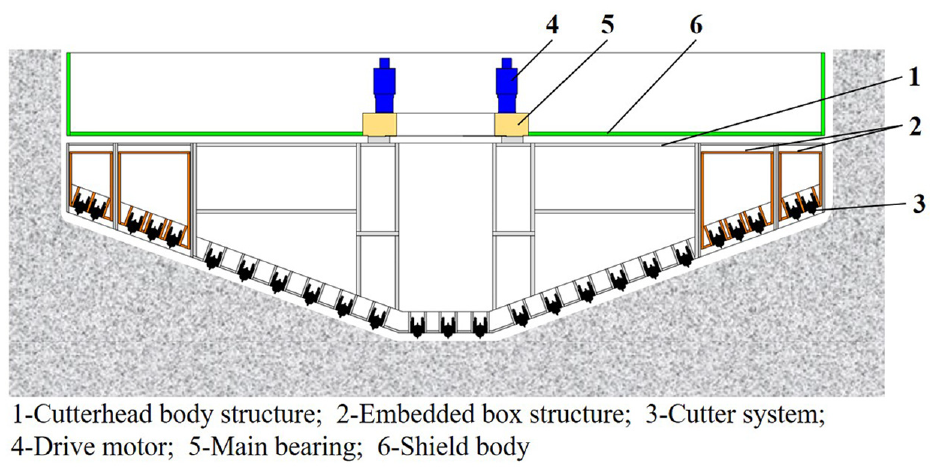
The SBM and TBM realize excavation through the cutterhead penetration and rotation, the cutterhead is powered by the drive system, and the muck produced by excavation is transferred to the outside of the tunnel/shaft through the mucking system, their working principles are the same. The SBM and TBM include cutterhead, shield body, drive system, much removal system, etc. The cutterhead is composed of a body structure and some cutter system, the cutter system is installed on the body structure and can be replaced once damaged, the cutter system and the body structure are fixed together during the working process of the cutterhead. The drive system mainly includes drive motors and the main bearing, the cutterhead is installed on the main bearing, and the main bearing is used to transmit the power of the drive motors to the cutterhead, the structure comparison of SBM and TBM is illustrated in Figure 1.

Structure comparison between SBM and TBM: (a) main structure of SBM and (b) main structure of TBM (Original figure of SBM cited from Herrenknecht AG 32 ).
Although the working principle and structure composition of TBM/SBM are similar, however, it can be seen from Figure 1 that there are significant differences in the structure profile of the cutterhead. The TBM cutterhead is a planar structure, while the SBM cutterhead is a conical structure, which is mainly determined by its working characteristics. TBM is normally used for horizontal or low slope (less than 5°) tunnel excavation, the muck is produced by cutterhead excavation, then the muck falls in the bottom space under the gravity condition, and finally, the muck is discharged through screw conveyor, hydraulic pipeline, or belt conveyor,4,33 as illustrated in Figure 2. The planar structure of the TBM cutterhead is more conducive to much removal. Besides, the TBM needs to maintain the stability of the excavation face,34,35 and the planar cutterhead is more beneficial to stabilize the excavation face.

Schematic diagram of TBM muck removal process: 1: muck falls to the bottom of the tunnel, 2: muck is transferred to the outside of the tunnel.
SBM excavates the shaft vertically downward, and there is no risk of collapse on the excavation surface, so the cutterhead does not need to maintain the stability of the excavation surface, however, the muck removal of SBM is more difficult than TBM. If a planar structure similar to the TBM cutterhead is adopted, it will be difficult for automatic accumulation of muck, which is detrimental to the discharge of muck. Therefore, the SBM Cutterheads generally adopt a conical structure, the muck can slide down to the center along the conical excavation face under the gravity condition, and finally is transferred to the outside of the tunnel, as illustrated in Figure 3. There are two main ways of SBM muck removal, one is the upward muck removal mode when the muck is gathered in the center, it is lifted and discharged outside of the shaft through the hydraulic pipeline or other ways, as illustrated in Figure 3(a). The other is the downward muck removal mode, which needs a bottom haulageway for muck removal, before SBM excavation, the pilot hole needs to be excavated first, and the muck fall to the bottom haulageway through the pilot hole, then collected in the bottom haulageway and discharged, as illustrated in Figure 3(b).
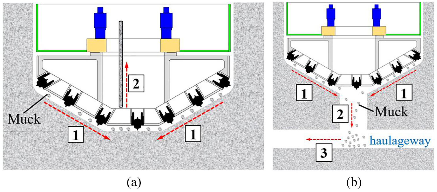
Schematic diagram of SBM muck removal process: (a) upward muck removal mode, 1: muck slides onto the center of the shaft, 2: muck is lifted and discharged outside the shaft and (b) downward muck removal mode, 1: muck slides to the center of the shaft, 2: muck falls to the bottom through the haulageway pilot hole, 3: muck be collected in the bottom haulageway and discharged.
Challenges of the existing mega SBM and TBM cutterhead
With the rapid economic development and accelerated urbanization process, the super large-scale cities have gradually become a trend, but along with that is the problem of land resource scarcity in urban core areas and environmental protection has become increasingly obvious. Due to the high space utilization rate of super large diameter tunnels/shafts, it is helpful to alleviate the problems caused by the shortage of land resource, such as heavy traffic. The market demand of super large diameter tunnels/shafts is increasing in recent years, as a result, the construction equipment with better performance is also required.36,37 For example, in the construction of larger diameter urban traffic tunnels (especially across rivers, lakes, sea waters, etc.) or underground parking lots, the environmental-friendly mega TBM/SBM is undoubtedly a very good choice, because the use of mega TBM/SBM has little impact on the ground and surrounding environment, most importantly, it can build more lanes and parking position spaces with one-stage completion.
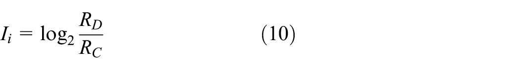
As a key component of SBM/TBM, mega SBM/TBM not only means the increase in cutterhead structure size, workload, and manufacturing difficulty, but also directly affects the equipment drive system configuration, increasing equipment complexity, and cost. During the cutterhead design and drive system selection phase, the empirical formula is used as the reference for the working torque prediction, the formula is defined as 38 :

Where

Drive system of the TBM for SR99 tunnel project. 40
Herrenknecht AG has proposed a double cutterheads design scheme for mega TBM, including a central cutterhead and outer cutterhead, both cutterheads can be rotated independently in the clockwise and anti-clockwise directions as the cutterheads are powered by two independent drive systems, as illustrated in Figure 5. Compared with the single cutterhead, the main performance indicators such as the torque, thrust, eccentric force, overturning moment of the double cutterheads are smaller. 41 However, the machine needs two sets of cutterhead and drive system, which are installed together, the manufacturing difficulty and complexity of the equipment are higher. Therefore, the double cutterheads scheme is only used in a few engineering projects, and a large number of mega TBMs still use a single cutterhead design scheme.

Double cutterheads and drive systems of Mega TBM for the Madrid M-30 tunnel project, the central cutterhead and outer cutterhead are powered by two independent drive systems, both cutterheads can be rotated independently. (Original figure cited from Herrenknecht AG 42 ).
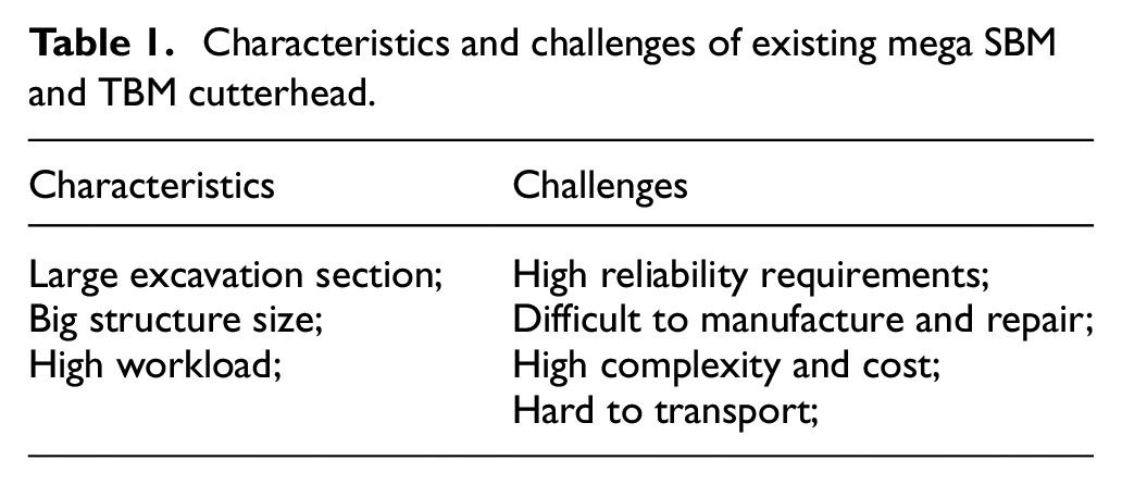
As for the cutterhead with a diameter of more than 20 m, it can be applied to the construction of some extreme large-diameter tunnels/shafts, but the manufacturing difficulty and reliability requirements of the machine are higher. As a result, the cost and manufacturing cycle of the machine increases sharply, and the maintenance is more difficult, the characteristics and challenges of mega SBM/TBM cutterhead are listed in Table 1.
Characteristics and challenges of existing mega SBM and TBM cutterhead.
Therefore, the existing cutterhead structure is needed to be improved, to reduce the load on the cutterhead during excavation, and the requirements of the drive system, besides, it can also ensure the reliability of the machine, so as to reduce the cost, shorten the manufacturing cycle, and improve the construction safety.
Methodology
To meet the needs of product innovation and optimization, it is necessary to constantly improve the existing products. How to generate new design ideas according to customer requirements is the key to product innovation. TRIZ tools, such as the Evolutionary Trends, Contradiction Matrix, and Invention Principle, can help designers quickly find new design ideas. The Independence Axiom can quickly guide the decomposition of functional requirements to obtain detailed schemes, and the combination of Information Axiom and fuzzy comprehensive evaluation can be used to select the best scheme and reduce the impact of human factors. The design method based on TRIZ and AD can provide directional and operable guidance for designers, making the innovative design process traceable, so as to quickly determine new schemes and improve design efficiency.
TRIZ
TRIZ provides a guiding method to solve practical problems during product development, which studying the internal laws and principles of the invention. TRIZ theory mainly includes three core ideas: (1) the development and evolution of technology system follows the objective law; (2) technical problems and contradictions are the driving force to promote the evolution process; (3) the ideal state of technology system development is to achieve the maximum benefit with the least resources. TRIZ provides a set of theoretical tools to solve invention problems, including the Invention Principles, Contradiction Matrix, Separation Principle, Ideal Final Results, etc.
The general process of applying TRIZ is as follows: firstly, defining the contradiction problem to be solved, then, converting the contradiction problem into a standard problem according to the TRIZ, and finally, using the tools of TRIZ to solve it.
Axiomatic design
AD aims to form a systematic process from product conceptual design to detailed design, and provide designers with a theoretical tool based on the logical and rational thinking process. AD believes that a good design needs to meet the Independent Axiom and Information Axiom. The Independent Axiom requires that the functional requirements of the design are independent of each other, and the Information Axiom requires minimizing the information content of the design scheme. Axiomatic design theory defines the design process as a zigzagged mapping of the functional domain

Where
Information Axiom is used to select the best scheme satisfying the Independence Axiom, that is, the design scheme with the highest success probability to achieve the goal of functional requirements. The information content

The success probability

Design process integrating TRIZ and AD theory
After long-term development, despite the TBM/SBM has formed a relatively mature design method, when the application field and customer requirements of TBM/SBM change, the existing design methods cannot guide the product technology innovation to meet the new requirements. Therefore, it is necessary to put forward a proper method for the technical innovation of TBM/SBM. The design process based on TRIZ and AD is as follows:
Step 1: Analyzing the innovative customer requirements of the new product, transforming the customer requirements into contradiction problems;
Step 2: Establish the TRIZ contradiction matrix to find the recommended Invention Principle, according to the Invention Principle, the designers can quickly find solutions to contradictory problems, and the creative ideas for new product design is obtained;
Step 3: Based on the creative design ideas, the Independent Axiom is applied to guide the detailed design, in the mapping process from functional domain
Step 4: Judge whether the design matrix is coupled, if it is, the TRIZ tools will be used for matrix until the design matrix is uncoupled. Then, judge whether the design matrix satisfies the Independence Axiom, if not, repeat the above mapping and decoupling process.
Step 5: The detailed design scheme is obtained according to the design matrix, if there are multiple feasible schemes, the Information Axiom and fuzzy comprehensive evaluation method are used to select the best scheme.
Step 6: The total information content of each feasible scheme is calculated, and the scheme with the least information content will be selected as the final design scheme.
The workflow of the proposed method is presented in Figure 6.

Workflow of the proposed approach.
Case study
This paper takes a mega SBM cutterhead with a diameter exceeding 20 m which was manufactured by CRCHI Co. LTD as an example, the design process of the new cutterhead scheme is described, at present, there is no reference case for the cutterhead design of this specification. By analyzing the functional requirements of the mega cutterhead, the design idea of the new cutterhead is put forward by using the proposed design method, and the cutterhead design scheme is finally obtained.
Customer requirements analysis
Due to the limitations of the existing cutterhead structure scheme with a diameter exceeding 20 m, to obtain a new product innovation idea, it is necessary to analyze the customer requirements of the mega cutterhead design.
(1) The cutterhead needs to meet the excavation of a large shaft, the cutterhead structure size increased with the increase of excavation diameter.
(2) As the excavation diameter increases, the driving torque required by the cutterhead will increase, it is expected that the driving torque required by the cutterhead as small as possible.
(3) The cutterhead needs to bear a greater working load during excavation, so it puts forward higher requirements for the reliability of the structure.
(4) To transport and install the machine easily, it is required that the weight and volume of the structure should not exceed limits.
(5) To reduce the manufacturing difficulties and costs, it is expected to use a low-power drive system and small main bearings, the complexity of the equipment shall be as low as possible.
According to the above customer requirements, the direction of cutterhead structure optimization can be determined.
Innovative idea generation
By analyzing the function and structural characteristics of the existing cutterhead, it can be known the working principle of the cutterhead. As the cutterhead rotates, the cutter systems installed on the cutterhead break the rock, the cutterhead is powered by the drive system. According to the AD, the functional requirements and the design parameters of the existing cutterhead can be divided into transmission and support

According to the above analysis, the mega cutterhead with a diameter exceeding 20 m is facing new customer requirements, it can be converted into TRIZ contradiction problem, which are described by general engineering parameters, 43 and the solution to the problem can be found in the contradiction matrix. The contradiction matrix is an arrangement of 39 improving parameters and 39 worsening parameters, and the solutions suggested in the cells of the matrix can help to resolve the contradiction problem. The list of 39 parameters and 40 Inventive Principles can be found in “TRIZ for Engineers 12 .” In order to design a novel mega cutterhead, several parameters need to be improved. The cutterhead can excavate a larger area, which refer to the No.5 (area of moving object). The structural strength of the cutterhead should be higher, which refer to the No.14 (strength). To facilitate transportation and assembly, the weight of the cutterhead should be as light as possible, which refer to the No.2 (weight of stationary object), and the volume of the cutterhead should be as small as possible, which refer to the No.8 (volume of stationary object). However, other parameters will deteriorate. The driving torque required by the cutterhead will increase, which refer to No.10 (force). The increase of cutterhead diameter leads to the increase of weight and volume, which refer to No.2 (weight of stationary object) and No.8 (volume of stationary object). The complexity of the equipment will also increase, which refer to No.36 (device complexity). Thus, the contradiction matrix of the innovative design of the mega SBM Cutterhead is constructed, as illustrated in Table 2.
TRIZ contradiction matrix.

The possible Invention Principles for solving contradictions can be found in the contradiction matrix:
(1) No. 1: Segmentation, dividing an object into independent parts, make an object easy to disassemble.
(2) No. 2: Taking out, separate an interfering part or property from an object, or single out the only necessary part (or property) of an object.
(3) No. 15: Dynamic, divide an object into parts capable of movement relative to each other.
(4) No. 19: Periodic Action, instead of continuous action, use periodic or pulsating actions.
According to the working characteristics of the SBM cutterhead, combined with the possible invention principle in the contradiction matrix, a preliminary scheme is obtained. Due to the working load of the cutterhead mainly comes from the rock breaking and the friction against the cutterhead, 44 considering that the SBM cutterhead is not required to maintain the stability of the excavation surface, consequently, the torque generated by friction against the cutterhead of the SBM accounts for a relatively low proportion of the total torque. Therefore, the torque generated by rock cutting is the main factor affecting the total torque of the SBM cutterhead, and it can also affect the structural reliability and equipment configuration. Based on the invention principles No. 1 (segmentation) and No.19 (periodic action), the existing integral continuous excavation mode is changed to a multi-step cyclic excavation mode, that is, the whole excavation face is divided into multiple annular sections for excavation. When the cutterhead excavates a certain annular section, only the cutter systems installed on the annular area of the cutterhead are used to cutting the rock. Based on the invention principle of No. 2 (extraction) and No. 15 (dynamic), the integral body structure is improved. The integral body structure is partially extracted, and a movable box structure is designed to change the existing body structure, which is embedded in the body structure and can move relative to the body structure, the embedded box structure moves together with the cutter systems installed on it. Besides, based on invention principle No. 1 (Segmentation) and the manufacturing experience of existing large-diameter cutterhead, the cutterhead body structure can be divided into multiple parts for manufacturing, to avoid the size and weight of individual parts exceeding the limit during transportation and installation. The preliminary scheme is illustrated in Figure 7.
Schematic diagram of the preliminary scheme of novel mega SBM cutterhead.
The new working principle of the novel mega cutterhead is illustrated in Figure 8. All the cutter systems installed on the novel cutterhead no longer work at the same time, only a part of the work in each work step, which greatly reduces the working load of the cutterhead, and the safety margin of the cutterhead is improved. As illustrated in Figure 8, the cross-section with a diameter exceeding 20 m is divided into three steps to excavate. Firstly, the cutter systems installed on the inner ring of the cutterhead excavate the face, when the inner ring excavation is completed, the cutterhead is lifted. Secondly, the embedded box structure of the middle ring extends, and the cutter systems installed on the embedded box excavate the middle ring subsequently, when the middle ring excavation is completed, the cutterhead is lifted again, and the embedded box structure is retracted. Thirdly, the embedded box structure of the outer ring extends, and the cutter systems installed on the embedded box excavate the outer ring, when the outer ring excavation is completed, the cutterhead is lifted again, and the embedded box structure is retracted. Finally, when the whole cross-section is excavated, the cutterhead starts the next stage of excavation. The new multi-step cyclic working mode is proposed to realize the excavation of cross-section with a diameter exceeding 20 m, in this way, the mega cutterhead can be driven by the low-power drive system, thus reducing the configuration requirements and overall cost of the machine.

Schematic diagram of multi-step cyclic excavation working principle of novel mega SBM cutterhead.
The structure and working mode of the existing SBM cutterhead are improved through the TRIZ, the movable embedded cutter box structure is adopted to change the integral body structure. The functional requirements and design parameters of the novel mega cutterhead are redefined as transmission and support multi-step excavation

Conceptual scheme design
To get the detailed design scheme, the highest level of the design matrix needs to be decomposed. The functional requirement

The cutter systems

According to the decomposition results of the function domain, draw on the experience of the existing cutterhead structure in use, the primary scheme of the cutterhead structure, in this case, is obtained, as illustrated in Figure 9.
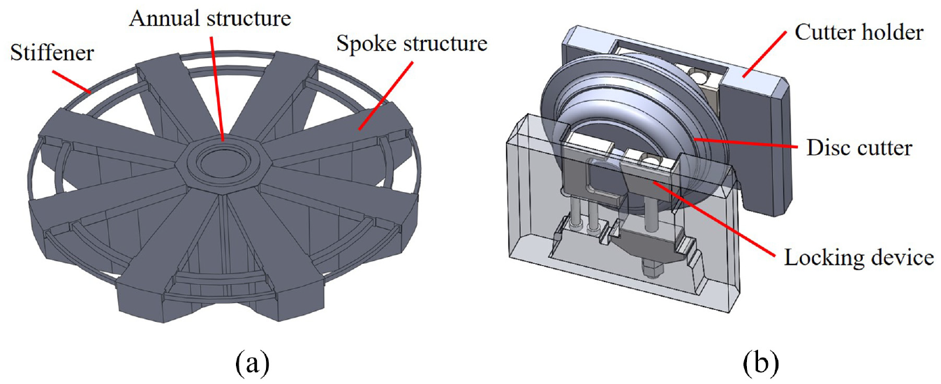
Schematic diagram of primary scheme: (a) body structure and (b) cutter system.
The functional requirement
The design parameter
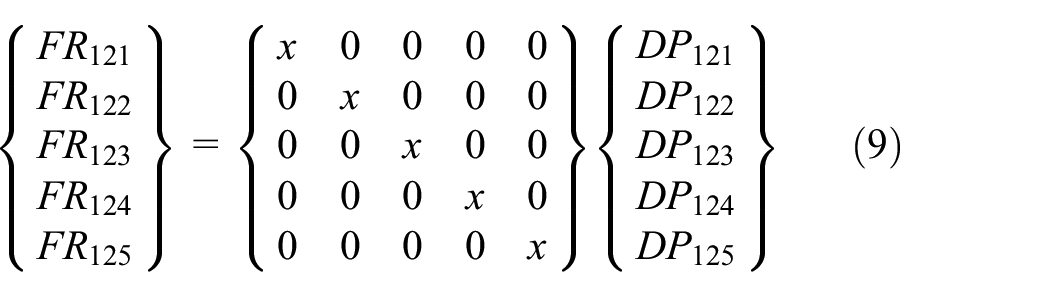
According to the above design matrix, two feasible design schemes meeting the requirements can be obtained. The structures of two feasible schemes are illustrated in Figures 10 and 11. There is a significant difference between scheme 1 and scheme 2, it can be seen that the structural forms of the mechanical locking device after embedded box extension

Schematic diagram of scheme 1: (a) embedded box retract state and (b) embedded box extend state.
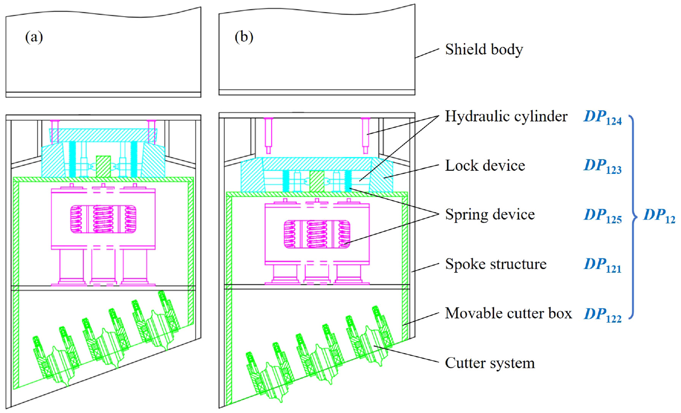
Schematic diagram of scheme 2: (a) embedded box retract state and (b) embedded box extend state.
So far, the design of a novel mega SBM cutterhead has been decomposed into leaf nodes to meet the principle of Independent Axiomatic. The relationship between functional requirements and design parameters is shown in Figure 12.

Relationship matrix between design parameters and functional requirements.
Evaluation of feasible schemes
When there are multiple feasible schemes during the scheme design process, it is necessary to select the best one. As for the indexes that can be quantitatively evaluated, the system information content can be easily calculated according to the Information Axiom, and it can be determined that the optimal scheme is the one with the least information content. However, some complex mechanical products usually can not directly obtain quantitative evaluation indexes, so it is necessary to convert the qualitative evaluation indexes with hierarchical concepts into quantitative values. The membership function of the evaluation index can be established by using the fuzzy mathematics theory, and its curve can be described in triangle, trapezoid, bell, rectangle and other forms, the trapezoid is easy to understand and can better express the characteristics of fuzzy variables, 45 so the trapezoidal membership function curve is selected in this paper.
Four evaluation indexes are determined according to expert opinions, and each evaluation index is divided into different levels, For example, the technical complexity is divided into “simple, relatively simple, general, relatively complex, and complex,” and the structural reliability is divided into “good, better, fair, worse and poor,” the installation difficulty is divided into “easy, relatively easy, general, more difficult and difficult”; and the environmental adaptability is also divided into “good, better, fair, worse and poor,” the membership function curve corresponding to the evaluation factors can be divided into five levels “

Membership function curve of qualitative evaluation index.
The area enclosed by the membership function curve of the design range is defined as the fuzzy design range, and the area enclosed by the membership function curve of the system range is defined as the fuzzy system range, besides the overlapping area between the fuzzy design range and the fuzzy system range is defined as the fuzzy common range, as shown in Figure 14. To describe the satisfaction of the fuzzy system to the fuzzy design range, this paper defines the calculation equation of fuzzy information content is written as follow:
Where

Schematic diagram of fuzzy design range, system range, and common range.
The cutterhead functional requirements of the technical complexity, environmental adaptability, and installation difficulty should reach the level “
Information content Statistics of feasible scheme evaluation indexes.

As can be seen from Table 2, the total information of scheme 1 is 2.43, while the total information of scheme 2 is 8.43. The total information of scheme 1 is significantly lower than that of scheme 2. According to the Information Axiom, scheme 1 is better, so scheme 1 is determined as the final design scheme. Besides, considering the weight reduction and structural strengthening of the body structure, the three-dimensional schematic diagram of the final design scheme is obtained, as shown in Figure 15.

Design scheme of the novel mega SBM cutterhead: (a) overall structure of cutterhead, (b) movable cutter box structure for middle ring excavation, (c) movable cutter box structure for outer ring excavation, and (d) cutter system.
Conclusion
Aiming at the innovation and optimization requirements of complex mechanical products, this paper proposes an innovative design method integrating TRIZ and AD theory, it has been successfully applied to guide the design of a mega SBM cutterhead with a diameter exceeding 20 m. Firstly, the customer requirements of the mega SBM cutterhead are analyzed. Then, the innovative idea of cutterhead improvement is obtained based on TRIZ theory, combined with the working principle and structural characteristics of the cutterhead, the detailed scheme design is completed based on AD theory. Finally, a novel scheme to meet the customer requirements is obtained. The innovation of the new scheme is changing the working mode of the existing SBM cutterhead, a new movable cutter box is added to the existing SBM cutterhead body structure, and the integral continuous excavation mode of the cutterhead is transformed into a multi-step cyclic excavation mode. As a result, the working load of the novel mega cutterhead during the working process is significantly reduced, thereby the reliability and safety margin of the cutterhead structure is improved. Besides, the drive system configuration requirements of the machine are reduced, so the mega cutterhead with a diameter exceeding 20 m can be driven by the low-power drive system, thus, the manufacturing difficulty and cost of the whole machine are greatly reduced. The design scheme obtained in this paper is not only suitable for mega SBM cutterhead, but also mega TBM cutterhead.
The main benefit of the proposed design method is to help designers quickly find product innovation ideas, and generate feasible schemes that meet the new customer requirements. The qualitative evaluation of products is transformed into the quantitative evaluation of information content index, which is convenient for judging the good and bad of new design schemes, it can reduce the influence of subjective factors, to select the best scheme. According to the new product design, this method can effectively improve design efficiency.
However, there may be multiple schemes that can satisfy the functional requirements, owing to the limitation of design time and knowledge of the designer, this paper finally gives two schemes that meet the requirements, and the better one is selected as the final scheme. For the key components of a complex mechanical system, experienced designers can quickly find feasible solutions from few design schemes. When designing a new complex mechanical system with many functional requirements, it will be very hard for designers to explore a large number of potential solutions. In the future research, the technology of artificial intelligence, database and machine learning can be used to help designers get more solutions efficiently, and a design case library is worth establishing, it will greatly improve the application scope of the proposed design method.
Footnotes
Handling Editor: Chenhui Liang
Declaration of conflicting interests
The author(s) declared no potential conflicts of interest with respect to the research, authorship, and/or publication of this article.
Funding
The author(s) disclosed receipt of the following financial support for the research, authorship, and/or publication of this article: This work was supported by the special funding support for the construction of innovative provinces in Hunan Province (No.2019GK1011) and the Project of State Key Laboratory of High Performance Complex Manufacturing, Central South University (No. ZZYJKT2021-15).