
Abstract
Corner separation occurs easily in highly loaded compressor stators. This paper proposes a novel slot inside the stator blade, with the slot inlet located at the blade leading edge and the slot outlet located at the suction surface, by using the momentum of the incoming flow to form a high velocity jet to control the development of the boundary layer on the blade suction surface. For 3D compressor cascades, the influence of the key geometrical slot parameters on the flow fields in the slot and cascade passage and the aerodynamic performance of the cascade were investigated with a numerical method. Then, the stator blades in a highly loaded compressor stage were slotted to improve the flow in the stator blade passages. The main results can be summarized as follows. The use of slotted blades in the cascade effectively suppresses corner separation. When the cascade inlet velocity is high or the inlet flow is at a positive attack angle, the separation control effect improves. In the highly loaded compressor stage, slotted stator blades considerably reduced the flow loss at the stator corner, and the stage efficiency increased over the entire flow rate range. Furthermore, two cascades with unslotted and slotted blades were tested. The experimental and numerical results were consistent, demonstrating that the total pressure loss coefficient of a cascade can be effectively reduced by slotting the blades in the cascade.
Introduction
In the late 1960s, Rockenbach proposed slotting inside compressor blades and used the pressure difference between the pressure and suction surfaces to form jets and control the development of the boundary layer on the suction surface. Various slot configurations were developed for the rotor and stator blades of single-stage axial compressors. The experimental results showed that the slot suppressed flow separation in the middle section of the blade but had no positive effect on corner flow control. 1 Mikolajczak et al. 2 and Fottner 3 experimentally investigated flow fields in cascades with slotted blades, and the results showed that the flow loss control was not only unsatisfactory but also had a negative effect (the loss increased). Sturm et al. 4 hypothesized that the low speed of the slot outlet caused these suboptimal results and proposed using an external air source to form jets to actively control the boundary layer on the blade suction surface, with the jet speed equivalent to the local mainstream speed and the jet direction as parallel to the mainstream direction as possible. Sinnette and Costello 5 studied the feasibility of jet flows improving the aerodynamic performance of compressors via theoretical analyses.
On highly loaded compressor cascades, Wiederhold et al. 6 used jet flows to suppress the development of boundary layers on the blade surfaces and reduce blockages in the cascade passages. The results showed that when the jet flow rate was 0.5% of the main flow rate, the static pressure ratio increased by more than 10%. On the test bench of a four-stage low-speed axial compressor, Kirtley et al. 7 used an external jet to control the boundary layers on blade suction surfaces to design ultralow solidity third-stage stators. Nerger et al. 8 used an external air source to generate jets on blade suction surfaces and endwalls to control corner flow in highly loaded low-speed cascades. The experimental results showed that the method increased the static pressure of the cascade. The studies of Fottner 3 and Gmelin et al. 9 showed that the effect of the jet on the performance of the compressor was related to the flow rate and direction of the jet. The jets produce by external air sources effectively reduced the flow loss; however, if the air source input energy was considered, profits were difficult to obtain.
To reduce the flow rate of the jet and thus decrease the energy input of the air source, Culley et al. 10 used an unsteady jet to control corner flows in the stator of a multistage low-speed axial compressor. The experimental results showed that better results were obtained by using an unsteady jet with the same flow rate as a steady jet. Gmelin et al. 9 obtained similar results on a highly loaded subsonic cascade via experiments and calculations. Zander and Nitsche 11 used cascade experiments to show that unsteady jets can strengthen mixing in the boundary layer by introducing external potential flows and delaying separation and blockages in the corners. Active control methods use external air sources to generate steady/unsteady jets. These methods can produce the desired jet speed on the blade suction surfaces and annular wall surfaces simultaneously, and the jets can be closed when control is not needed. However, these methods require external air sources, as well as high-frequency air valves to produce unsteady jets.
Slotting between a blade pressure surface and the suction surface to form a jet on the suction surface is simple and does not require an external air source; however, the resulting jet speed is usually low, and the control effect may not be satisfactory. Recognizing the lack of slotting methods, Cao et al., 12 Zhang et al., 13 and Wang et al. 14 proposed a convergent two-segment turning slot to reduce the difference between the directions of the main flow and jet outlet and increase the jet speed, thereby improving the control effect of the jet on the development of the boundary layer (see Figure 1). Moreover, the authors conducted a series of studies. For 2D cascades, the results showed that the slot can reduce flow loss at positive attack angles. For 3D cascades, the results showed that slotting near the blade hub or tip can reduce corner separation.15–18 For a single-stage compressor, slotting near the stator blade hub can effectively improve compressor efficiency at the design point and the stall margin.15,19–24
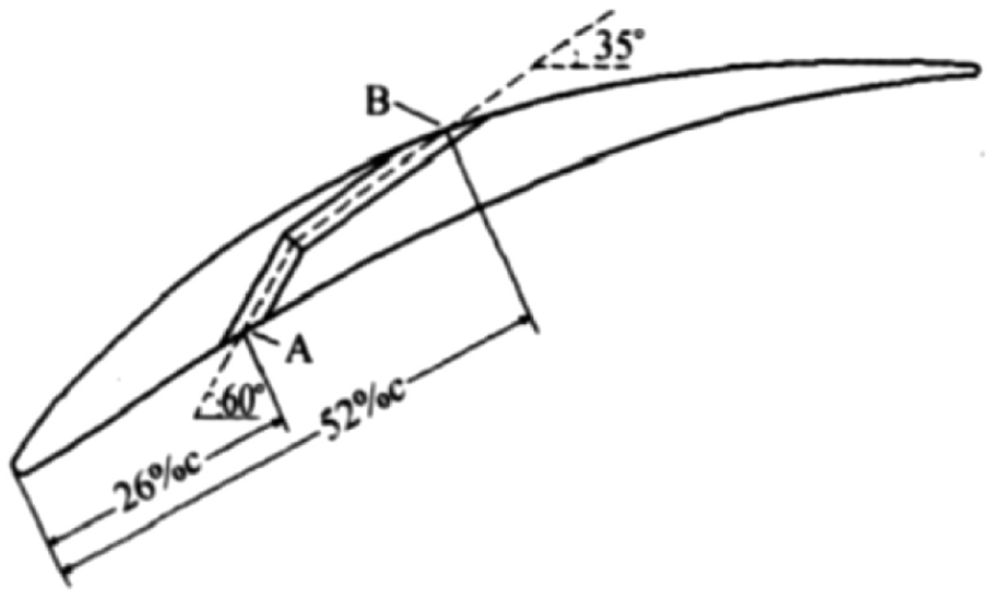
Convergent turning slot between two segments in the blade profile. 17
Sun et al. 25 and Yumeng et al.26,27 proposed creating two slots at the hub of a compressor blade to form three segments with a wing-like shape, which increased the flow rate in the slot and reduced the mixing loss between the jet and the main flow. For a highly loaded cascade, the experimental results showed that the two slots suppressed open separation and effectively improved the aerodynamic performance under multiple working conditions (especially at positive attack angles). The control effect of the two slots on the corner flow is better than that of one slot. 27
This paper proposes a new slotting method in which the velocity momentum of an incoming flow is used to form a high-speed jet. The effects of the main geometric parameters of the slot on the flow fields and aerodynamic performance of cascades with medium and high loads were investigated, and the stator blades in a highly loaded compressor stage were slotted to suppress corner separation in the stator blade passages and improve the stage efficiency.
Analysis of flow fields in a 3D slotted cascade
The slot in a compressor blade profile is shown in Figure 2. The air enters the slot at the blade leading edge and exits from the suction surface. In this paper, a 2D slotted cascade with a diffusion factor of 0.45 was extended into a 3D slotted cascade. The main parameters of the cascade are shown in Table 1, and the 3D slotted blade in the cascade is shown in Figure 3.

Slot structure.
Main parameters of the cascade.


The 3D slotted blade.
The flow fields in the cascade were simulated using NUMECA software; the Spalart-Allmaras turbulence model was selected, and H-shaped structured meshes were generated by Igg operation in the NUMECA software. Due to the small angle between the slot outlet and the suction surface in the slotted cascade, to ensure good grid orthogonality, two grid blocks were added to the H-shaped structured meshes near the slot outlet in the unslotted cascade, as shown in Figure 4.

Grid structure: (a) whole grid, (b) local grid near the leading edge, and (c) local grid near the slot outlet.
In the flow field simulation, the surface at blade middle was set as a symmetrical surface, only calculation results of half of the blade height were shown. The lower boundary is the endwall (solid wall), so Mach number tends to zero. The advective terms were discretized in second order upwind format. Generally, in numerical simulation of the flow field in turbomachinery, Spalart-Allmaras model is considered to be relatively accurate and the maximum yPlus should be less than 10. In the flow field simulations in this paper, the maximum yPlus value is 6.4 near the blade leading edge. As shown in Figure 5, when the number of grid cells in the cascade was increased to 330,000, the total pressure loss coefficient and flow turning angle remained approximately constant. Therefore, this number was used in the flow field calculations in this study.

Performance parameters of the cascade versus with the number of grid cells.
The aerodynamic performance of the slotted cascade (denoted as Slot 1) is shown in Figure 6, and that of the corresponding unslotted cascade (denoted as Unslotted) is shown in the same figure for comparison. As shown in Figure 6, over the entire attack angle range, the flow loss of the slotted cascade is smaller than that of the unslotted cascade, and the flow turning angle of the slotted cascade is larger than that of the unslotted cascade, especially at positive attack angles. As the angle increases, the thickness of the boundary layer on the suction surface increases, and the effect of the slot suppressing the boundary layer becomes more noticeable.

Performance of the unslotted and slotted cascades.
Figure 7 shows the limit streamlines on the blade suction surfaces. For cascades that are symmetrical about the middle of the blade, only half of the figure is shown. Figure 7 shows that at large positive and negative attack angles and zero attack angles (namely, −6°, 0°, and 8°), large corner separation occurs in the unslotted cascade passage, with larger attack angles leading to larger separation regions. The corresponding separation region is noticeably smaller in the slotted cascade passage.

Limit streamlines on the blade suction surfaces: (a) Unslotted and (b) Slot 1.
Moreover, Figure 8 shows that at the above three attack angles, compared with the unslotted cascade, the total pressure loss and outlet flow angle decrease (namely, the deviation angle decreases) near the blade hub in the slotted cascade due to the reduced corner separation; therefore, the number of blockages in the region decreases. Furthermore, the flow rate near the blade hub increases, which causes the flow rate and AVDR near the middle of the blade to decrease, resulting in an increase in the flow diffusion degree, flow loss and deviation angle near the middle of the blade.

Distributions of the aerodynamic parameters along the blade height: (a) at an attack angle of −6°, (b) at an attack angle of 0°, and (c) at an attack angle of 8°.
Table 2 shows that at an attack angle of 0°, the total pressure loss coefficient in slot
Aerodynamic parameters.

Based on the above comparison of the slotted and unslotted cascades, the overall effect of slotting is established. Next, the effects of the key geometric parameters of the slot on the slotted cascades are analyzed to better understand the flow characteristics of slotted cascades. As the loss increases, the deviation angle increases and the flow turning angle decreases; however, the influence of the key slot parameters on the flow turning angle is not analyzed further.
To evaluate the numerical method used in the above investigation and compare the aerodynamic performance of cascades with unslotted and slotted blades, several cascade flow field experiments were performed.
The experiments were performed on a plane cascade experiment bench at the Nanjing University of Aeronautics and Astronautics. The experimental bench includes an intermittent wind tunnel, and the air source is a 100 m3 high-pressure gas tank supplied by two compressors with high pressure ratios. The boundary layers at the upper and lower walls and sidewalls are sucked by a 200 m3 vacuum tank connected to three 200 kW vacuum pumps. The blade height in the cascades is 110 mm. The static pressures on the blade surfaces were measured by holes on the surfaces, and the wakes of the cascade were measured by five hole probes. Pressures in the five hole probes and on the blade surfaces were measured using a pressure scanning valve, the pressure sensor accuracy is 0.25%. Measurement uncertainties include pressure sensor accuracy, pressure sensor calibration errors, and transmission interference of electrical signals of the sensor. The overall error is not more than 0.5%. The uncertainty of isentropic Ma is determined by the uncertainty of the measured pressure. In these experiments, the suction of the boundary layers on the upper and lower walls and sidewalls was not considered.
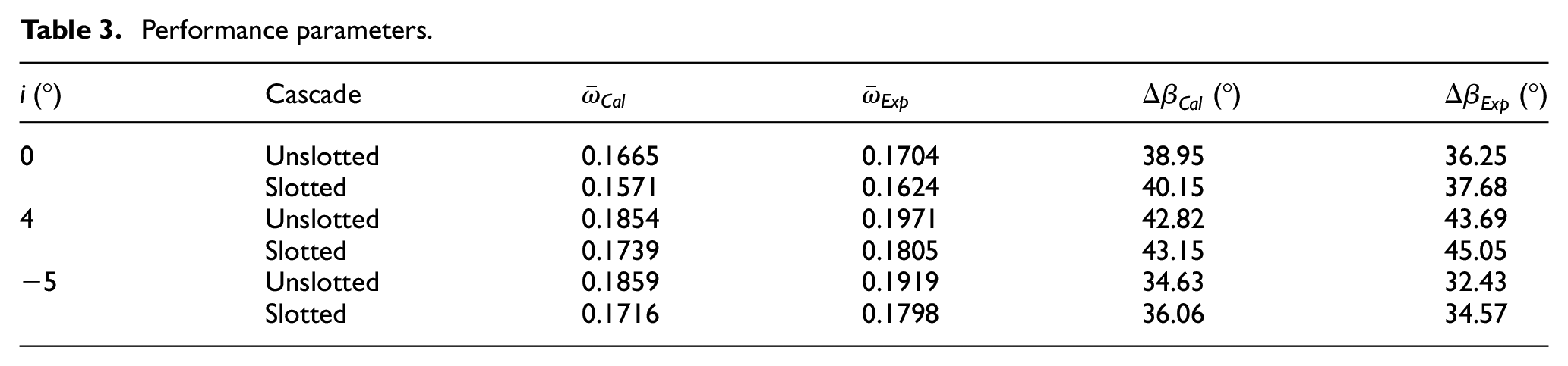
Figure 9 shows the isentropic Mach number distributions on the blade surfaces of slotted and unslotted cascade blades at an inlet Mach number of 0.75 Ma and an attack angle of 0°. Figure 10 depicts the distributions of the total pressure loss coefficient and the flow turning angle along the blade height at an attack angle of 0°. Table 3 shows the total pressure loss coefficients of the cascades at different attack angles. The figures and table indicate that the calculation results are in good agreement with the experimental results, demonstrating that the total pressure loss coefficient of a cascade can be effectively reduced by slotting the blades in the cascade.

Distributions of the isentropic Mach number on the blade surfaces at an attack angle of 0°: (a) at 50% of the blade height, (b) at 25% of the blade height, and (c) at 10% of the blade height
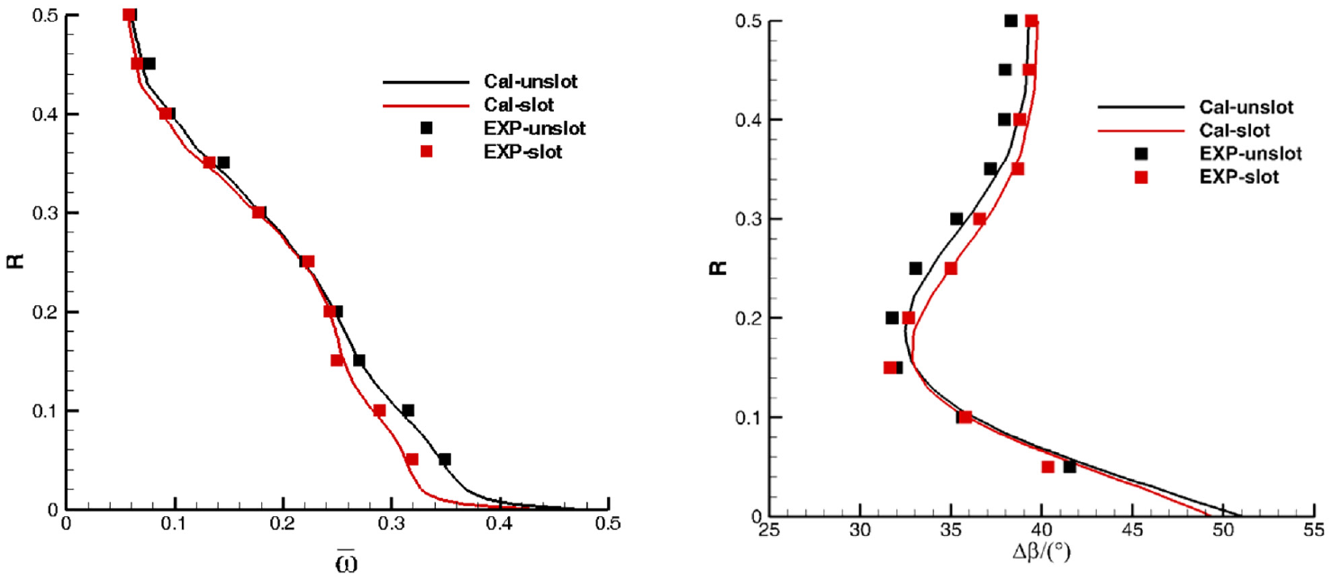
Parameter distributions along the blade height at an attack angle of 0°.
Performance parameters.
Effects of the key geometric parameters of the slot on the flow fields in the slotted cascade
Influence of the slot height
In Slot 1, the blade was slotted from the blade hub to the tip, and the slot was straight along the blade height. To study the effects of the slot height, the height of Slot 1 was reduced to 25% and 10% of the blade height from the blade hub, yielding two new slotted cascades, which are denoted as Slot 2 and Slot 3 (see Figure 11).
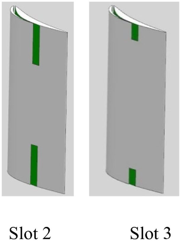
3D slotted blades.
Figure 12 shows that at large positive attack angles, shorter slots lead to an increased pressure loss. However, at large negative attack angles, only small differences between the total pressure losses of the three slotted cascades and unslotted cascade are observed.
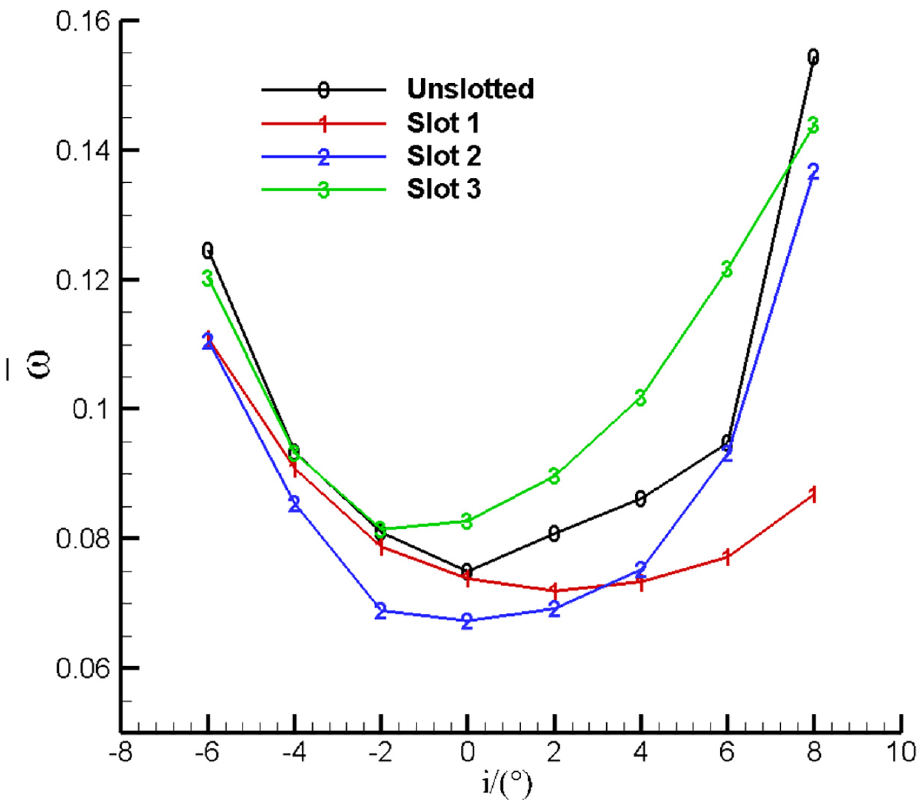
Performance of cascades with different slot heights.
Figure 13 shows that the losses near the blade hub in the three slotted cascades (Slot 1, Slot 2, and Slot 3) are significantly smaller than that in the unslotted cascade, which indicates that the slots effectively control the corner separation. However, the losses in the slotted cascades near the middle of the blade are greater than those in the unslotted cascade. At an attack angle of −6°, the three slotted cascades have approximately the loss near the middle of the blade. At an attack angle of 8°, the shorter the slot height is, the greater the loss near the middle of the blade. Figure 14 shows that the slot at the middle of the blade effectively controls boundary layer separation on the blade suction surface at large positive attack angles. Compared with the unslotted blade, the boundary layer separation at the blade middle did not be controlled by the slot. But if there is no slot at the blade middle, the separation at the blade middle will be larger. Because the slot near the blade hub suppresses the corner separation, which deteriorates the flow near the blade middle.

Total pressure loss coefficient along the blade height.

Mach number cloud maps at the blade middle at an attack angle of 8°.
According to the above analysis, slots near the blade hub can effectively control corner separation. However, when the corner separation is controlled, the AVDR near the middle of the blade decreases, and the inverse pressure gradient near the blade middle increases, which deteriorates the flow and results in flow separation near the middle of the blade (especially at large positive attack angles). Therefore, when the blade is slotted at the hub, the slot must be located at the middle of the blade; that is, the whole blade height must be slotted to ensure that corner separation control can be achieved without worsening or alleviating the adverse effects on the flow near the blade middle.
Influence of the slot outlet location
The outlet of Slot 1 is located at 60% of the axial chord length. To study the influence of the slot outlet location, the outlet of the slot was moved to 85% and 25% of the axial chord length without changing the outlet width, yielding slotted cascades that are denoted as Slot 4 and Slot 5. Figure 15 shows the limit streamlines at an attack angle of 0° on the blade suction surface of the unslotted and three slotted cascades. Figure 15 demonstrates that the slot in Slot 5 is located upstream of the corner separation, the slot in Slot 1 is located in front of the corner separation, and the slot in Slot 4 is located at the rear of the corner separation.
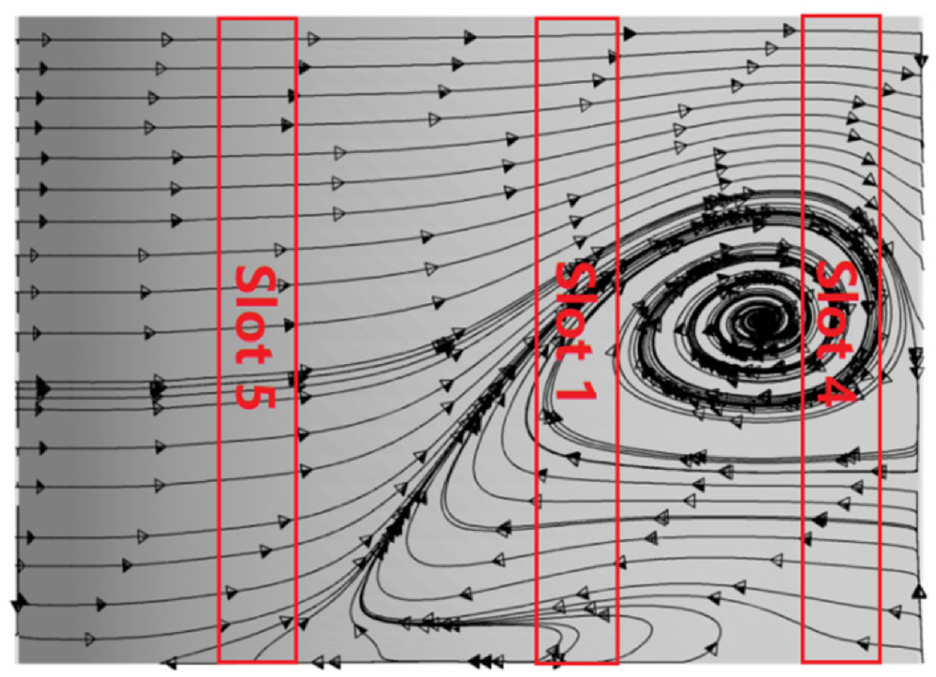
Limit streamlines on the blade suction surface of the unslotted cascade at an attack angle of 0°.
Figure 16 shows that the difference in the total pressure losses between Slot 1 and Slot 5 is small in the attack angle range. However, the loss of Slot 4 is noticeably larger at positive attack angles and smaller at negative attack angles than those of Slots 1 and 5.
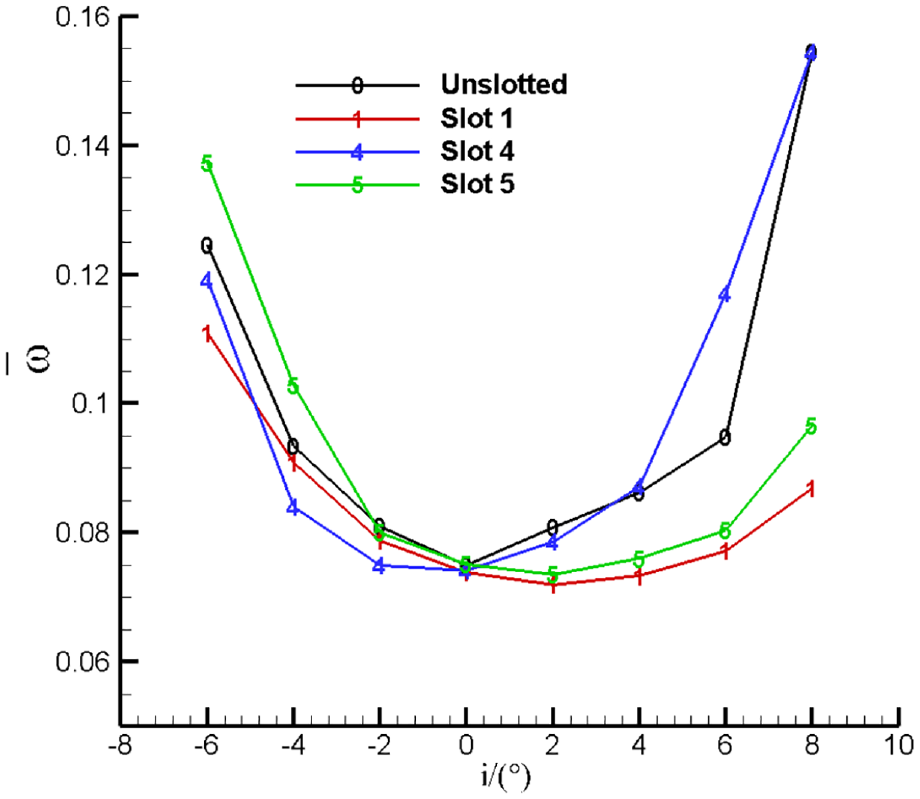
Performance of cascades with different slot outlet locations.
Figure 17 shows that, compared with the unslotted cascade, the loss near the blade hub is significantly reduced by the slots at the different axial outlet locations. Therefore, the corner separation control effect is approximately independent of the slot location. The slot has a small corner separation control effect only for Slot 5 at an attack angle of −6° because the boundary layer on the blade suction surface is very thin due to the large negative attack angle and the upstream slot location; thus, in this case, the loss near the blade hub is nearly the same as that in the unslotted cascade.

Total pressure loss along the blade height.
According to the above analysis, to effectively suppress corner separation, the slot outlet at the blade hub should be located near the corner separation, and the corner separation suppression effect is weak if the slot is upstream of the corner separation region. Moreover, if the slot outlet at the blade middle is near the blade leading edge or trailing edge, the slot cannot effectively control the development of the boundary layer on the suction surface near the blade middle. If the slot outlet is near the blade leading edge, where the boundary layer is very thin, or the trailing edge, where the boundary layer is fully developed, the boundary layer control effect is poor. Therefore, the axial location of the slot outlet should be changed along the blade height to improve the aerodynamic performance of the slotted cascades.
Influence of the location of the slot outlet along the blade height
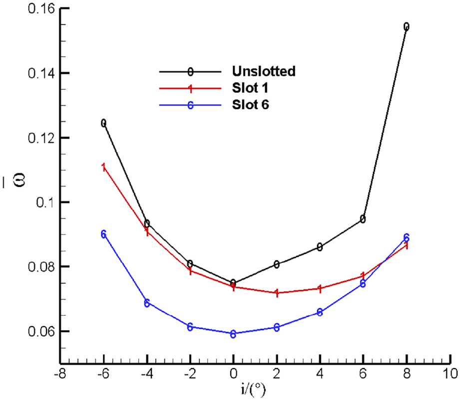
Based on the above analysis, the slot outlet location at the middle of the blade should be upstream of that at the blade hub. To confirm this argument, the slot outlet location at the blade hub was kept unchanged in Slot 1 (60% of the chord length), the slot outlet location at the blade middle was moved upstream to 30% of the chord length, and the position between the hub and middle was changed linearly along the blade height, thus obtaining a cascade denoted as Slot 6, as shown in Figure 18.

Slot in Slot 6.
Figure 19 shows that, compared with the straight slot in Slot 1, the loss of the inclined slot in Slot 6 across the full attack angle range was significantly reduced, with the reduction increasing as the attack angle decreased. Moreover, Figure 20 shows that, compared with Slot 1, the loss in the corner region of Slot 6 effectively decreases, while the loss near the blade middle increases. Furthermore, the slot outlet location near the blade middle may not be optimal and should thus be further improved. In engineering designs, the slot outlet location should not change linearly along the blade height.
Performance of the cascades.

Total pressure loss coefficient along the blade height.
Influence of the flow rate in the slot
The flow rate in the slot has a considerable influence on the control of the flow field in the blade passage. Therefore, to investigate this influence, the flow rate was changed by increasing the outlet width of Slot 6 by 50% and 100%, thus obtaining the slotted cascades denoted Slot 7 and Slot 8. Table 4 shows that the wider the slot is, the greater the flow rate in the slot and the higher the flow loss in the slot.
Performance parameters of cascades with different slot outlet widths.

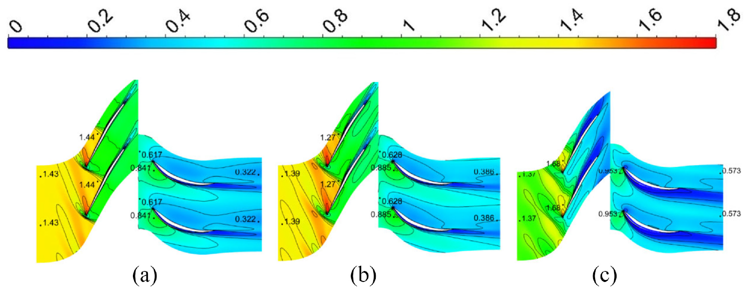
Figure 21 indicates that, compared with Slot 6 and Slot 8, in the overall attack angle range, Slot 7 has the lowest flow loss, and either too large or too small a flow rate in the slot is not conducive to reducing the flow loss in the cascade. Furthermore, Figure 22 shows that the flow loss in the potential flow region in Slot 8 (which has the widest slot blades) is significantly larger than that in Slot 6 and Slot 7, and the corresponding separation on the suction surface is also larger. To investigate the influence of the distribution of the flow rate in the slot along the blade height, Slot 9 was formed by adopting the widths of Slots 6 and 8 at the blade middle and blade hub, respectively, with the width between the hub and the middle varied linearly along the blade height. The Slot 9 results are shown in Figures 21 and 22.

Performance of cascades with different flow rates in the slot.

Total pressure loss coefficient along the blade height.
The above analysis demonstrates the flow rate in the slot and its distribution along the blade height have optimal values and that too large or too small values are not conducive to controlling the flow in the corner region and the suction surface boundary layer in the potential flow region.
To further evaluate the effects of the Mach number at the cascade inlet on the aerodynamic performance of the slotted cascades, the flow fields in the unslotted cascade and Slot 7 (which has the best aerodynamic performance among the considered slotted cascades) were simulated at inlet Mach numbers of 0.6, 0.7, and 0.75, and the performance is shown in Figure 23. Moreover, the geometrical parameters of Slot 7 were applied to a highly loaded cascade with a diffusion factor of 0.6 (the key geometrical parameters are shown in Table 5). Figure 24 shows the performance of the unslotted and slotted cascades at inlet Mach numbers of 0.6, 0.7, and 0.8. Figures 23 and 24 demonstrate that (1) because the boundary layer on the suction surface at a positive attack angle is thicker than that at a negative attack angle, the cascade performance is improved more by using slotting at positive attack angles than at negative attack angles; (2) the higher the inlet velocity of the cascade, the higher the flow momentum in the slot, and the better the improvement effects; (3) the larger the diffusion factor, the thicker the boundary layer on the suction surface, and the better the improvement effects; and (4) because a small inverse pressure gradient appears on the suction surface at negative attack angles, the performance improvement with slotting is weak, and the performance worsens (the flow loss increases) at negative attack angles.

Slot 7 performance.
Key geometrical parameters of a highly loaded cascade.


Highly loaded cascade performance.
Application of slots in stators in the highly loaded compressor stage
The practical effect of stator blades slotting in highly loaded compressor stages were examined in this section. The main parameters of the compressor stage are shown in Table 6. According to the above results, the proposed slotting scheme for the blades is shown in Figure 25. The outlet location of the slot at the blade middle is upstream of the outlet locations at the blade hub and tip, and the outlet location changes linearly along the blade height.
Main parameters of the axial compressor stage.


Slot in the stator blade.
The ratio of the number of grid cells in the rotor passage to that in the stator passage with unslotted blades is 1.2, and the ratio of the number of grid cells in the rotor passage to that in the stator passage with slotted blades is 0.87. Figure 26 shows that for the stage with slotted stator blades, as the number of grid cells in the rotor passage increases to 600,000, the total pressure ratio and efficiency remain approximately constant; thus, the number of grid cells in the rotor passage and the stator passages with unslotted and slotted blades was set to 600,000, 500,000, and 690,000, respectively, in the subsequent flow field calculations.

Variation in the performance parameters with the number of grid cells in the rotor passage.
Table 7 shows that at the design point, the total pressure loss coefficient of the stator with slotted blades is considerably less than that of the stator with unslotted blades; therefore, the efficiency of the stage with the slotted stator is higher than that of the stage with the unslotted stator blades, and the stall margin of the stage with the slotted stator blades is slightly smaller than that of the stage with the unslotted stator. Moreover, Figure 27 shows that at the design point, large corner separation occurs near the corner region in the stator passage with the unslotted blades, and the corresponding separation in the stator passage with the slotted blades is substantially reduced. Figure 28 shows that the efficiency of the stage with the slotted stator blades is noticeably higher than that of the stage with the unslotted stator blades throughout the flow rate range; however, the efficiencies of the two rotors are approximately equal.
Performance parameters at the design point.

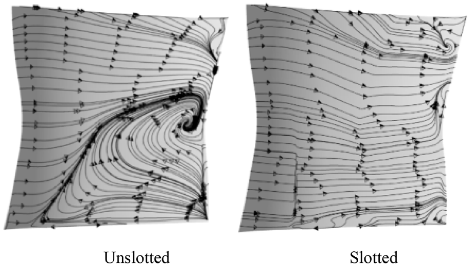
Limit streamlines on the suction surfaces at the design point.

Performance during different stages.
As previously mentioned, the stator with slotted blades had a reduced stall margin. This effect is analyzed as follows. Figure 29 shows that as the number of calculation steps increases, the shock wave near the rotor blade tip moves upstream, and the separation regions in the rotor and stator blade passages increase. Therefore, the instability during this stage is caused by the shock wave near the rotor blade tip exiting the blade passage, which also leads to instability in transonic and supersonic compressors. Near the stall point, the static pressure at the outlet of the slotted stator is greater than that at the outlet of the unslotted stator (see Figure 30(a)); since the corner separation is reduced by slotting the blades, the passage expansion near the blade hub increases, which leads to a decrease in static pressure at the stator inlet (namely, the rotor outlet) and an increase in the pressure gradient along the blade (see Figure 30(b)). When the two stages with the slotted and unslotted stators have the same flow rate, the total pressure ratios of the two rotors are approximately equal (see Figure 30(b)); that is, the average total pressures at the two rotor outlets are approximately the same. Therefore, the average static pressures at the two rotor outlets are approximately equal because the flow rates and average total pressures at the outlets are approximately the same. Thus, at the same flow rate, the static pressure at the blade tip of the outlet of the rotor matched with the slotted stator is larger than that matched with the unslotted stator. The increase in the static pressure at the blade tip of the rotor outlet causes the stall during this stage. Therefore, the stall margin of the stage with the slotted stator is smaller than that of the stage with the unslotted stator.
Mach number cloud maps at 90 blade heights at different stall point calculation steps: (a) at 1300 steps, (b) at 1500 steps, and (c) at 1700 steps.

Static pressure distributions along the blade height: (a) at the stator outlet and (b) at the rotor outlet.
The slot in the corner suppresses the corner separation. However, when the corner separation is controlled, flow capacity near the blade hub increases and the AVDR near the blade tip decreases. Therefore the inverse pressure gradient near the blade tip increases, which deteriorates the flow near the blade tip. The blade tip slot is to improve the flow near the blade tip.
To compare the performances of a stator with and without blade tip slot, the slot from 80% to 100% blade height in the stator in Figure 25 is removed (see Figure 31). Figure 32 shows that the blade tip slot can decrease boundary layer thickness and wake size.

The slotted blade without blade tip slot.

Mach number cloud maps near blade tip: (a) with blade tip slot and (b) without blade tip slot.
Conclusion
In this paper, an innovative blade slotting scheme, with the slot inlet located at the leading edge of the blade and the slot outlet located at the suction surface of the blade, was proposed to suppress corner separation in compressor stator passages. In 3D compressor cascades, the influence of the key geometrical slot parameters on the flow fields in the slot and cascade passage and the aerodynamic performance of the cascade were investigated with a numerical method. Then, the stator blades in a highly loaded compressor stage were slotted to improve the flow in the stator blade passages. The conclusions of this work can be summarized as follows (Table 8).
(1) The slot near the blade hub effectively controls corner separation. However, when corner separation is controlled, the AVDR near the middle of the blade decreases, and the inverse pressure gradient increases, which deteriorates the flow and results in flow separation on the blade suction surface near the middle of the blade (especially at large positive attack angles). Therefore, when the blade is slotted at the hub, the slot must be located at the blade middle; that is, the whole blade height must be slotted to ensure that the corner separation control effect can be achieved without worsening the flow near the blade middle or alleviating the adverse effects on the flow near the blade middle.
(2) To effectively suppress corner separation, the slot outlet at the blade hub should be located where corner separation has developed, and the corner separation suppression effect is weak if the slot is upstream of the corner separation region. If the slot outlet at the blade middle is near the blade leading edge or trailing edge, the slot cannot effectively control the development of the boundary layer on the suction surface near the blade middle. Moreover, if the slot outlet is near the blade leading edge, where the boundary layer is very thin, or near the blade trailing edge, where the boundary layer is fully developed, the boundary layer control effect is insufficient. Therefore, the axial location of the slot outlet should be changed along the blade height to improve the overall aerodynamic performance of the slotted cascade.
(3) Because the boundary layer on the suction surface at positive attack angles is thicker than that at negative attack angles, the cascade performance is improved more by using slotting at positive attack angles than at negative attack angles. The higher the inlet velocity of the cascade is, the higher the flow momentum in the slot and the better the improvement. Furthermore, the larger the diffusion factor is, the thicker the boundary layer on the suction surface, and the better the improvement.
(4) For a highly loaded compressor stage, the efficiency of the stage is higher with slotted stator blades than with unslotted stator blades across the whole flow rate range. However, the slotted blades in the stator decreased the stall margin. When the corner separation effect is reduced, the static pressure at the blade hub of the rotor outlet decreases, while the static pressure at the blade tip of the rotor outlet increases. The stall during this stage is due to the shock wave at the rotor blade tip exiting the blade passage. Therefore, the stall margin during this stage is smaller with the slotted stator than with the unslotted stator.
(5) The experimental results are consistent with the numerical results, demonstrating that the total pressure loss coefficient of a cascade can be effectively reduced by slotting the blades in the cascade.
Main findings.

Footnotes
Appendix
Handling Editor: Chenhui Liang
Declaration of conflicting interests
The author(s) declared no potential conflicts of interest with respect to the research, authorship, and/or publication of this article.
Funding
The author(s) disclosed receipt of the following financial support for the research, authorship, and/or publication of this article: National Science and Technology Major Project (2017-II-0001-0013).