
Abstract
Correlational studies of vibration characteristics theory of exhaust system, optimization design of idling vibration control and the noise test analysis were conducted to solve the problems of body vibration and exhaust noise under idling condition. Firstly, the analysis of vibration mode, dynamic response and vibration transfer of exhaust system were carried out by using the simulation analysis, and the location of the exhaust system hangers were verified. Furthermore, the structure optimization schemes of exhaust system were proposed for exhaust noise reduction under idling condition based on control of local stiffness optimization, constraint location optimization and system global stiffness optimization. Finally, the interior and exhaust noise and system vibration of optimization schemes were tested under idling condition, and the exhaust noise was verified under rapid acceleration condition respectively. Meanwhile, the vibration response of exhaust system was analyzed. Results showed that the optimization schemes had better noise attenuation effect than the original scheme under idling and rapid acceleration conditions, indicating that it was necessary not only to effectively avoid the idling frequency interval of engine, but also to improve the structural stiffness and the vibration of local structure according to the vibration mode, and minimize the modification of the internal structure of the exhaust system.
Introduction
As the source of vehicle power, the engine not only provides sufficient and continuous power in the process of vehicle driving, but also transmits its own vibration as an incentive to each part of the vehicle. If not controlled, it will inevitably lead to the deterioration of the vehicle NVH (Noise, Vibration, and Harshness) performance and affect the comfort of the vehicle. As an important part of the vehicle, exhaust system is not only complex in structure and varied in vibration excitation, but also an important path of vibration transmission between engine and body. 1 Therefore, to study and optimize the vibration characteristics of exhaust system is not only beneficial to improve its own vibration and noise level and improve its service life, but also plays a very important role in improving the vehicle NVH level.2,3
Research has shown that vehicles generally have the phenomenon of body vibration and oversized exhaust noise under idling condition, which is probably related to the resonance between the exhaust system and vibration excitation of the engine. Therefore, the structural performance analysis and resonance decoupling of the exhaust system can effectively solve the problem of body vibration and oversized exhaust noise under idling condition. In structural performance analysis of the exhaust system, not only the static characteristics should be analyzed, but also the dynamic model of the exhaust system should be established to study its dynamic characteristics. 4 Statics calculation is usually used to check the strength and stiffness of the structure and analyze the force and displacement of the system. Modal analysis is the basic work of dynamic characteristic analysis, which can obtain the inherent properties of the structure and provide a basis for the vibration analysis, fault diagnosis and prediction and optimization design of the exhaust system structure. 5 Frequency response analysis can calculate the response of the system in the frequency domain and predict whether the design optimization of the structure can overcome the problems of resonance, fatigue and other adverse effects caused by forced vibration.
This paper studies the solutions and optimization schemes of idling noise directed at the vibration characteristics of the exhaust system and based on the theory of structure vibration mechanism. Through the studies of three methods of modal strain energy, local vibration mode and system stiffness control, structural optimization schemes are proposed in order to avoid the resonance frequency of the engine and achieve the purpose of optimizing the idling noise and vibration under idling condition.
Theory of modal and vibration response
A mode is an inherent property of a structure, which is only related to the shape of the structure, the form of constraint, the property of the material, etc., and has nothing to do with other inputs. According to the classical definition of modal analysis, modal analysis is an analysis process based on the vibration of a linear system and aimed at obtaining modal parameters of the system. 6 The main purposes of modal analysis are as follows: (1) To understand the resonance region of the structure, determine the modal parameters, such as natural frequency, damping, mode shape, etc., and provide guidance for the structure design; (2) To verify the accuracy of the numerical calculation model; (3) To be the basis of transient analysis and spectrum analysis.
Frequency response refers to the response of the structure to a certain load (impact load or load with a certain frequency within a certain range). The purpose of frequency response analysis is to determine the input-output relationship between two points on the structure. The total vibration response of the system is composed of the superposition of different vibration amplitudes and circular frequencies. The part of the transient response will gradually decay to zero due to damping, while the steady-state part of the response exists with the presence of the excitation. 7
For automobile exhaust system, the suspension point (hanger constraint position), vibration excitation point and stiffness will affect the exhaust system modal parameters and vibration response.
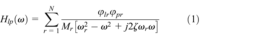
Under single point excitation, the frequency response function between the excitation point p and the response point l is8,9
If the frequency of the excitation force is ωr, the approximation is obtained as follows:

For linear systems, the amplitude of the frequency response function is proportional to the amplitude of the displacement response, then

For a damping system with a multi-excitation point structure with N degrees of freedom, the expression of the real mode frequency response function of excitation at point p and response at point l is as follows:

In equation (4), Ker is the rth order equivalent stiffness and Ker = Kr/(φlrφpr), gr is the damping ratio of the rth order modal structure and
Natural frequency
The natural frequency can be determined from the intersection of the real frequency curve and the residual compliance line, or from the frequency corresponding to the peak of the virtual frequency curve when ω = ωr. Because the peak is sharper, ω is easy to determine.
Damping ratio
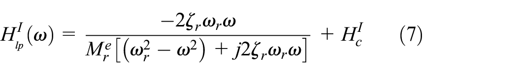
When ω approaches ωr, ωr plays a leading role and is called the main mode. Other modes which near ωr but are weak coupling or which are far away from ωr can be approximated as a complex constant Hc. Therefore, equation (1) can be approximated as

By transforming equation (5), the real part and the imaginary part are respectively

The damping ratio coefficient ζ can be determined by the half-power bandwidth. In equation (6), the characteristic curve is derived by differentiating against ω as follows:

For structural damping system, its damping ratio coefficient is
Modal shape
For the main mode, when
By measuring the value of

For rth order mode,

Modal stiffness
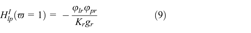
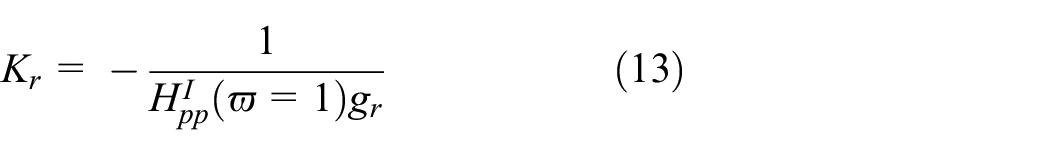
For the frequency response function of the excitation point p and the response point l, when

Taking the frequency response function value of the origin p and normalizing the origin, then the rth order modal stiffness Kr of the structural damping system can be expressed as
Modal mass
The modal mass can be expressed as

Therefore, as long as the transfer function is known, the modal parameters can be calculated through the analysis software. For the exhaust system in this paper, the main structural factors affecting the vibration transfer function are the position and properties of the exhaust system hanger (constraint point), local modal stiffness and global modal stiffness of the system.
Vibration isolation rate of exhaust system
The exhaust system has six degrees of freedom in space, and the analysis of the vibration isolation rate of all degrees of freedom will be very complicated. Therefore, the exhaust system with six degrees of freedom is usually decoupled into six independent systems with single-degree of freedom, and then the vibration isolation rate analysis is carried out on them. 10
The rotation of engine crankshaft is the excitation source of exhaust system vibration. Therefore, assuming that the body and frame do not produce vibration, the dynamic equation of exhaust system can be written by single variable analysis method as follows:

Assuming simple harmonic motion of the system, the exciting force is

In equation (16), F is the amplitude of the exciting force, ω is the response frequency of the system. Assuming that the response of the system lags behind the excitation and φ is the lag angle, then the displacement response can be written as follows:

In equation (17), X0 is the response amplitude. Substituting equations (15) and (16) into equation (14), it can be obtained as follows:

Assuming that λ is the ratio of excited frequency to natural frequency, then

The force transferred to the vehicle body is as follows:

The amplitude of fb is as follows:

The definition of transfer rate is the absolute value of the ratio between the amplitude of the force transmitted to the response position and the amplitude of the excitation force, which is expressed as follows:

As can be seen from the above equation, if the vibration at the response is to be reduced, T should be less than 1, then (1 − λ2)2>1, so λ > 1.414. The value of the transfer rate depends on the designed frequency ratio λ and damping ratio ζ. When the designed frequency ratio λ is fixed, the larger the value ζ is, the smaller the value T is.
Analysis of vibration characteristics of exhaust system
The analysis of vibration characteristics of exhaust system includes vibration modal analysis, dynamic response analysis and vibration transfer analysis. Vibration modal analysis is the basic work of dynamic characteristic analysis, and modal analysis of the system can get the inherent properties of the structure, which can provide a basis for the vibration analysis, fault diagnosis and prediction of the exhaust system structure and optimal design. Dynamic response analysis can calculate the response of the system in the frequency domain, and can predict whether the design optimization of the structure can overcome the problems of resonance, fatigue, and other adverse effects caused by forced vibration. Vibration transfer analysis mainly analyzes the vibration energy of the engine excitation source transmitted by the exhaust system to the body by the parameters of each hanger in the exhaust system, based on which the rationality of the hanger position is verified.
Establishing finite element mesh model
To study the vibration characteristics of exhaust system, a complete and effective finite element analysis model of exhaust system should be established first. The exhaust system of the objective vehicle in this paper is composed of manifold catalytic converter, bellows, three-way catalytic converter, front and rear-mufflers, exhaust pipes, hangers, and rubber suspension, as shown in Figure 1.

Exhaust system structure of the objective vehicle.
Establishing simplified models of components
There are plenty of complex sub-modules in exhaust system structure. It is very important to simplify the structure reasonably and establish accurate and effective finite element models. The component grid element and simplified models are shown in Table 1.
Component grid element and simplified models.

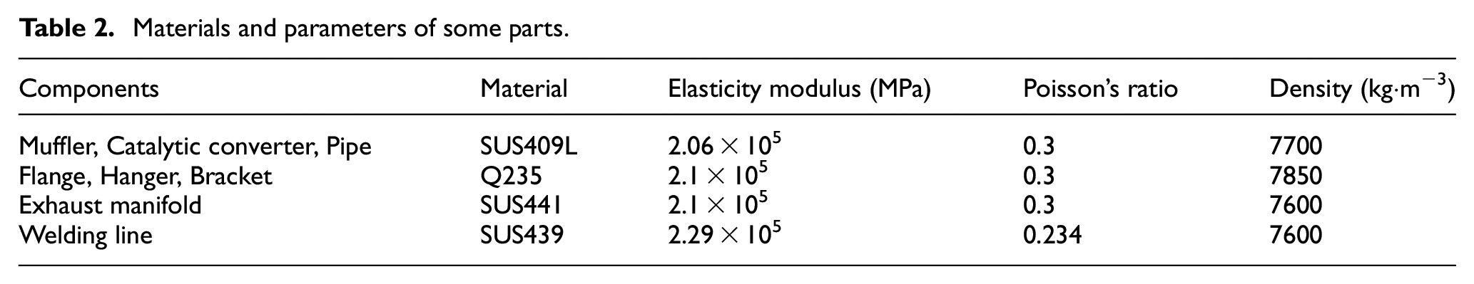
The connection relationship between the parts is established and the material attached to each part of the attribute parameters is created to complete the establishment of the finite element model. Some materials and parameters are shown in Table 2.
Materials and parameters of some parts.
Establishing powertrain and mount models
The vibration excitation caused by powertrain is one of the main factors in exhaust system excitation. Powertrain usually refers to the engine and transmission and related components integrated into the transmission. 11 The powertrain is connected to the frame or body by its flexible mount system. The mounting system not only needs to bear the mass of the powertrain, but also has the function of isolating the vibration of the powertrain. 12 The performance of powertrain mounting system has a significant impact on the vehicle NVH performance. When simplifying the powertrain, it is usually regarded as a rigid structure with elastic support. Without considering the influence of the torsional stiffness of the mount, the powertrain mount is simplified as a spring damping element in three directions, as shown in Figure 2. 13

Simplified model of powertrain mounting.
Ignoring the specific structure of the powertrain, it can be simplified as a center of mass, and a “Mass” element with mass and rotational inertia can be created at the center of mass. The powertrain mount is simplified as a “Spring2” spring damping element containing stiffness and damping, one end is rigidly connected to the powertrain centroid using a multi-point coupled MPC (Multi Points Constraint), and the other end is subjected to a displacement constraint of six degrees of freedom. The bolt holes and mounting holes of the intake flange plate at the hot end of the exhaust system are also connected with the simplified engine centroid by rigid elements. 14 The established finite element simplified model of powertrain is shown in Figure 3.

Simplified finite element model of powertrain.
The centroid coordinates and parameters of the powertrain are shown in Tables 3 and 4 respectively.
Centroid coordinates of the powertrain.

Centroid parameters of the powertrain.

There are four mounting points in the finite element simplified model of powertrain, and the mounts coordinates and stiffness parameters are shown in Table 5.
Powertrain mounting coordinates.

Statics analysis of exhaust system
Statics calculations are generally used to check the strength and stiffness of structures. The static simulation of exhaust system is mainly to judge the static equilibrium state of the system by analyzing the force of the hangers and the displacement of the system, and the static calculation is also the basic work of the fatigue analysis of the system. The static analysis of the system is carried out based on the finite element model of exhaust system. 15 The system gravity load of 1g is loaded, and the end of each mounting system connected to the car body is restrained by zero displacement with six degrees of freedom. The force analysis results of each hanger were shown in Table 6.
Results of static analysis of the hangers.

As can be seen from the results in Table 6, the average force of hangers is 23.3 N under 1g gravity load, and the overall force is relatively balanced. Compared with other hangers, the constraint reaction force of hanger 4 is slightly larger, exceeding 30 N. Hanger 2 and 3 are symmetrically distributed on the front dissipation shell, the force difference is only 1.5 N, and the exhaust system will not produce large torque and obvious roll phenomenon.
The cloud diagram of node displacement distribution of the exhaust system in Figure 4 shows that the maximum vertical displacement of the entire exhaust system is 2.399 mm, which occurs at the Pre-muffler, and the static displacement of the exhaust system is in an acceptable range.

Displacement cloud diagram of exhaust system.
According to the statics analysis, the force of the exhaust system is reasonable except that the force of hanger 4 is too large, and the system displacement is less than 3 mm in the acceptable range.
Modal analysis of exhaust system
Modal analysis can provide theoretical basis for system dynamic characteristic analysis, structural fault detection and prediction, structural dynamic design and optimization. Mode is an inherent attribute of mechanical structure, and the corresponding natural frequency and modal shape can be obtained for any mode. Modal analysis includes free mode and constrained mode. 16
Free mode
Free mode refers to the exhaust system mode that is not affected by any constraints. When calculating the free mode of the exhaust system, the vibration excitation of the powertrain is ignored, and its own structural mode is analyzed separately, so as to exclude the influence of other components. Hypermesh software is used as the pre-processing tool and Abaqus software as the solver. Lanczos method is used for the modal algorithm. Extraction of partial free modes of the system is shown in Table 7.
Partial free mode of exhaust system.

After removing the local modes, the first six modal shapes of the system are listed as shown in Figure 5. It can be seen that bending vibration patterns of exhaust system are mainly concentrated in the X and Y directions of the vehicle coordinate system. For example, the first vibration mode is first-order bending in the Y direction, the second vibration mode is first-order bending in the Z direction, the fourth vibration mode is second-order bending in the Y direction, and the fifth vibration mode is second-order bending in the Z direction. The torsional vibration of the exhaust system occurs in the X direction. For example, the sixth order is the first order torsional vibration around the X direction, and the exhaust system vibrates locally. The bellows in the exhaust system have multiple local vibration modes, and the torsional vibration at the Rear-muffler in the seventh vibration mode is significant.
First six free modal shapes of the system: (a) f1 = 10.59 Hz, (b) f2 = 18.60 Hz, (c) f3 = 27.78 Hz, (d) f5 = 30.46 Hz, (e) f7 = 58.40 Hz, and (f) f8 = 61.12 Hz.
Constraint mode
The constrained mode is to simulate the constrained mode of the exhaust system under the real installation state. The involvement of the powertrain will not only hinder the simulation of the real constraints of the exhaust system, but also affect the analysis of the dynamic performance of the exhaust system. 17 Therefore, the powertrain system is considered in the exhaust system constraint modal analysis, and the manifold connecting the powertrain and the exhaust system is taken into account. 18
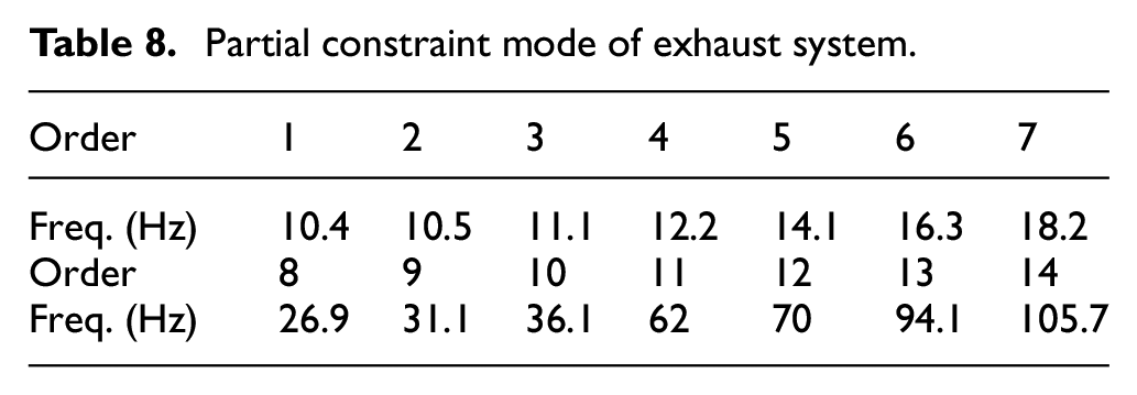
The constraint condition of the system is zero displacement constraint of six degrees of freedom on the end of powertrain mounting and exhaust rubber mounting connected to the vehicle body. Abaqus software is also used as the solver, Lanczos method is used to calculate exhaust system constraint modes, and extracted frequencies are shown in Table 8.
Partial constraint mode of exhaust system.
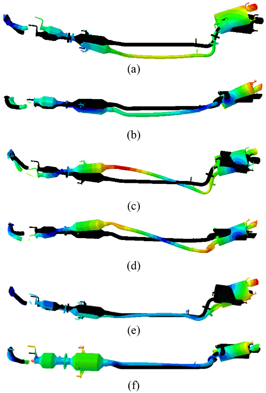
After removing the local modes, the first six constraint modal shapes are listed as shown in Figure 6.

First six constraint modal shapes of the system: (a) f1 = 12.15 Hz, (b) f2 = 26.87 Hz, (c) f3 = 31.09 Hz, (d) f5 = 36.05 Hz, (e) f7 = 62 Hz, and (f) f8 = 70 Hz.
The results in Figure 6 shows that the bending vibration of constrained modes of exhaust system mostly occurs in the Y and Z directions. For example, the 8th and 10th modes are the first and second order bending vibration in the Y direction respectively, and the ninth mode is the first order bending vibration in the Z direction. The torsional vibration mode of the exhaust system is the same as the free mode, which is the torsion of the exhaust system around the X-axis. The local vibration of the exhaust system components is also quite obvious, and the local vibration of the Rear-muffler in the 8th and 11th modes is obvious.
The engine involved in this paper is a 4-cylinder 4-stroke gasoline engine, and the idle speed is 800 r/min. Therefore, it can be inferred that the engine idle excitation frequency is 26.67 Hz. As can be seen from Table 8, the eighth natural frequency of the exhaust system constrained mode is 26.87 Hz, which is close to the engine idle excitation frequency. In idling condition, the vibration of the exhaust system may intensify due to resonance phenomenon, and the exhaust system needs further optimization.
Frequency response analysis of exhaust system
Frequency response analysis refers to the calculation of dynamic responses of structures under periodic loads varying with frequency in the frequency domain. The exhaust system is affected by many excitations during the operation of the vehicle. The engine excitation will lead to the vibration of exhaust system, which will have a considerable influence on the vibration of car body. Excessive force transferred to the body due to the vibration of the exhaust system will cause noise and vibration of the body. Therefore, it is necessary to analyze the response force of the hangers at each suspension of the exhaust system to judge the status of the transfer force of the exhaust system. Modal superposition method is used to calculate the transfer force of exhaust system hangers. The frequency response calculation model in this section is extended to the previous constrained mode calculation model, that is, the exhaust system dynamics model considering the effects of powertrain and exhaust manifold shown in Figure 7.
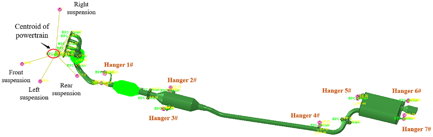
Finite element model of constrained mode of powertrain-exhaust system.
The boundary condition of the exhaust system is that the fixed end of the engine mounting and the end of the rubber mounting connected to the body are constrained with six degrees of freedom and zero displacement. The engine speed of the vehicle is generally less than 6000 r/min, and the corresponding frequency is 200 Hz. Therefore, the excitation frequency is generally selected as below 200 Hz. The engine mentioned in this paper adopts transverse structure, so the excitation torque is around the Y-axis of the vehicle. Therefore, when loading is added, the engine excitation is simplified as the torque with amplitude of 100 N/m, bandwidth of 0–200 Hz, direction around the Y-axis of the vehicle coordinate system, and the power assembly centroid is selected as the operating point. When responding to the output, the frequency response curve is set to draw 200 points, that is, 1 point is output every 1 Hz.
The force transmitted by the exhaust system to the vehicle body is mainly caused by the vibration in the vertical plane of the exhaust system, namely Z-direction. Therefore, the Z-direction transfer forces of the exhaust system hangers are taken as the main research object. Figure 8 shows the responsive force results of exhaust system hangers with the engine excitation. 19
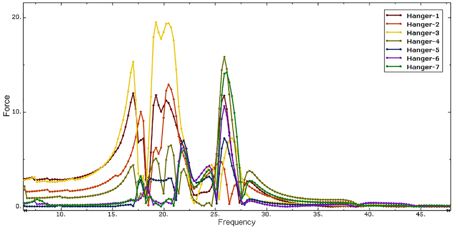
Responsive force curves of each hanger.
From the observation of response force results, it can be seen that the maximum peak value of hanger transfer force appears below 50 Hz, and the peak value of response force at this frequency band below 50 Hz is dense and varies in size. Due to the low speed and high vibration at the initial stage of engine startup, which is more unstable than that at normal operation, there will be a large vibration energy generation at the start-up stage, so the hanger response force will also produce a certain peak value at this stage. Therefore, this paper only discusses the response force results within the range of 1–50 Hz.
As can be seen from Figure 8, there are three large peak values in the whole frequency band, corresponding frequencies are 16, 18, and 26 Hz respectively. The maximum peak value is about 18 Hz. Hanger 3 has the maximum peak value of dynamic response force, hanger 1 and hanger 2 also have certain peak values, which are 11.7 and 12.6 N respectively. According to the noise frequency that can be felt by human ear and the vibration characteristics of exhaust system, the frequency response above 20 Hz is usually selected as the focus object. According to the analysis, hanger 4 of the exhaust system has a large response force peak value of 16.3 N at about 26 Hz, and the peak value of hanger 1, hanger 4, hanger 6 and hanger 7 are all greater than 10 N.
According to industry standards, it is generally required that the response force of the hanger of the exhaust system of a family car should not be greater than 10 N.20,21 However, in the 1–50 Hz frequency band concerned in this paper, large hanger responsive force appears, and multiple hangers have responsive force peaks greater than 10 N, which will lead to a large number of vibration of the exhaust system transmitted to the car body and cause vibration and noise in the car. At the same time, it can be seen that each hanger produces a large peak value almost simultaneously at about 26 Hz, and the idling frequency of the engine is 26.7 Hz. Combined with the above modal analysis results and frequency response analysis results, the peak value at this point is most likely due to idle resonance phenomenon in the exhaust system. Therefore, reducing the peak value of the response force of the hanger is an important link to solve idle resonance problem.
Verification of hanger positions
Whether the distribution of hanger position is reasonable has a very important influence on the vibration energy of the exhaust system to the body and the service life of the hanger. This section uses ADDOFD (Average Drive Degree Of Freedom) to analyze and study the reasonable hanger position of exhaust system. 22
Starting from the connecting flange in front of the bellows of the exhaust system, 105 points were successively selected every 30–50 mm, and these points were numbered separately to establish the set. Through the modal calculation, the displacement of the 105 points in each mode is obtained. The z-direction vibration of exhaust system is the focus of this paper, so the z-direction displacement of each point is used for weight accumulation. The calculated Z-weighted displacement is plotted as points and the ADDOFD curve is obtained. In this paper, the free mode and the constrained mode are calculated respectively, and the ADDOFD curves of free mode and constraint mode are obtained as shown in Figures 9 and 10 respectively.

ADDOFD distribution curve of free mode.

ADDOFD distribution curve of constraint mode.
Because the general trend of ADDOFD curve obtained by free mode and constrained mode calculation is the same, the optimal locations of exhaust system hangers are basically the same. The troughs in Figures 9 and 10 are the minimum points of ADDOFD curve, and a reasonable hanger location should be located at the exhaust system corresponding to this location.
The point corresponding to hanger 1 is at the peak value of ADDOFD calculation value, so it is not suitable for hanger layout. However, since this hanger is located behind the bellows and in front of the catalytic converter, the bellows are generally soft and the catalytic converter is heavy, so a hanger layout here can also support and share the weight of the system. Hangers 2 and 3 are located in the middle of the Pre-muffler, which is in good agreement with the ADDOFD calculation results. Hanger 4 is located in front of the exhaust pipe elbow, which is also a minimum ADDOFD value point, and can also be selected as a hanger layout point. Hangers 5, 6, and 7 are located in the main positions before or after the Rear-muffler, which are the best placements of hangers.
In short, although hangers 1, 5, 6, and 7 in the original exhaust system are not located at the point with the smallest ADDOFD value, the original exhaust system hanger layout has certain basis and is fully considered in all aspects considering the trend of the entire exhaust system, the limited chassis space, the limit and other requirements. However, according to the actual modal shape and analysis results of frequency responsive force, the location of the hanger can be optimized appropriately in the limited space for changing the hanger.
Optimization scheme design of idle vibration control
Because the exhaust system of the automobile has the problem of slight vibration and excessive noise value under idling condition, solving the resonance phenomenon of the exhaust system under idling condition is expected to improve the exhaust system and even the vehicle NVH level.
Strain energy refers to the potential energy stored in the body during the deformation process, and the strain energy calculated using mode shape and stiffness is called modal strain energy (MSE). The strain mode can identify the local property variation of the structure and accurately indicate the location of stiffness variation. Through the analysis of the distribution of modal strain energy, the weak parts of the structure are found out and optimized, which can effectively improve the vibration mode of the structure, avoid the idle resonance frequency, and achieve the purpose of controlling the idle vibration optimization and improving the idle noise.
Modal strain energy describes the amount of structural stiffness in terms of stress and strain. If the modal strain energy of a part of the structure is high, it indicates that the structure is weak and easy to be excited. The stiffness optimization of the local structure of the system and the distributed concentrated energy distribution can strengthen the inherent characteristics of the system structure change. The modal strain energy of the exhaust system is calculated at the same time as the modal analysis of the exhaust system. The modal strain energy (MSE) of j element of the i mode is defined as:

In this equation, {Φi} is the mode shape of the i mode and [Kj] is the stiffness matrix of j element. 23
From the above analysis, it can be seen that the frequency of the eighth mode in the exhaust system constrained mode is 26.87 Hz, which is in the idle excitation frequency range of the engine (around 26.67 Hz), and is the dangerous mode frequency. Moreover, the vibration mode of this order is torsional vibration around the X-axis. The vibration mode can be seen in Figure 6(b).
Considering the actual structural characteristics and installation form of the exhaust system, this paper improves the structure of the exhaust system from three directions: local stiffness optimization, constraint point location optimization and system global stiffness optimization, so that the eighth constraint mode avoided the engine excitation frequency and reduced the strain energy at the mode.
Optimization scheme A: Local stiffness optimization
According to the eighth order mode of 26.87 Hz of the original exhaust system, the modal strain energy distribution diagram is calculated as shown in Figure 11. The largest energy concentration is at the elbow behind the Pre-muffler. According to the above, the structural stiffness is weak at this point, and the modal strain energy can be reduced by local stiffness optimization for this weak point.

Modal strain energy at rear bend of pre-muffler.
The optimization scheme A is mainly based on the principle that a stiffener is welded at the rear bend of the Pre-muffler with concentrated energy using the modal strain energy control method to strengthen the structure, in order to disperse the concentrated energy and improve the modal frequency of this order, so as to avoid the effect of resonance interval. The local optimization mode of the structure is shown in Figure 12, and the modal strain energy of optimization scheme A is shown in Figure 13.
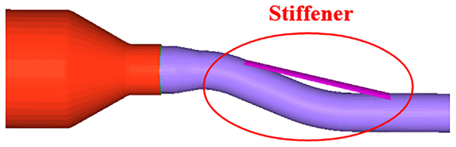
Local optimization scheme of modal strain energy (Stiffener).

Modal strain energy of optimization scheme A.
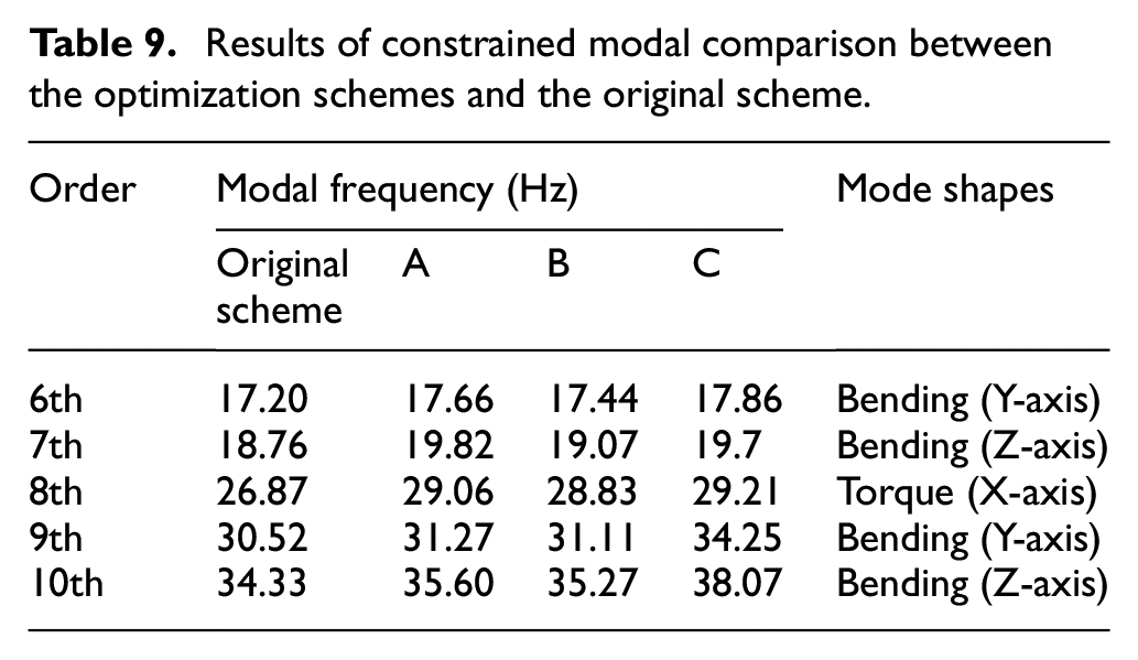
The simulation result of modal strain energy shows that the modal strain energy of optimization scheme A at the rear bend of the Pre-muffler is greatly improved, in which the concentration of modal strain energy is scattered. The constraint modal frequency of eighth mode changes from the original 26.87–29.06 Hz, and the detailed results is shown in Table 9 below. This is expected to solve the idle resonance and excessive noise problems of the original exhaust system.
Results of constrained modal comparison between the optimization schemes and the original scheme.
Optimization scheme B: Constraint location optimization
Optimization scheme B achieves the purpose of local mode control by changing the positions of hangers. The maximum torsion position of eighth order mode of the original exhaust system occurs in the Pre-muffler. Its mode shape is shown in Figure 14.

Local modal strain energy of eighth order constrained mode of exhaust system in rear-muffler.
The optimization scheme B is to move the hanger 5 in front of the rear muffler to the position with larger local modal strain energy, so as to improve the structural stiffness and the natural frequency of the exhaust system. Specifically, the hanger 5 is moved 60 mm to the right of the vehicle body, as shown in Figure 15.

Optimization scheme of local mode control (Moving hanger 5).
As can be seen from the simulation results which is detailedly shown in Table 9 below, the mode frequency of the eighth order constrained mode of the exhaust system optimized by scheme B increases from 26.87 to 28.83 Hz, avoiding the engine idle resonance frequency of 26.67 Hz to a certain extent. Although scheme B does not change the vibration shape of exhaust system, the problem of idle resonant noise can be solved by changing the local vibration mode. 24
Optimization scheme C: System global stiffness optimization
The research results show that the stiffness of the exhaust system can be increased effectively and the exhaust pressure loss can be reduced by increasing the diameter and wall thickness of the exhaust system. 25 In scheme C, the diameter of the exhaust pipe in the middle of the pre-muffler and rear-muffler is changed from 48 to 52 mm, and the wall thickness is changed from 1.0 to 1.5 m, so as to increase the rigidity of the exhaust system, change the constraint mode of the exhaust system, and increase the frequency of the eighth order torsional mode of the exhaust system from 26.87 to 29.21 Hz. At the same time, the frequencies of other modes is changed greatly compared with the optimization schemes A and B. The scheme C also failed to change the system vibration mode, but the increase of modal frequency is helpful to avoid idle resonance.26,27
The finite element models of exhaust system structure of the three optimization schemes are established, and the constrained modes are simulated and analyzed. The modal frequencies of some orders are compared with the original scheme, and the results are shown in Table 9. Therefore, three optimization scheme, although does not change the corresponding modal vibration mode, but the mode frequencies are increased. Compared to the original scheme, the three optimization schemes effectively avoid the idling incentive frequency of 26.67 Hz of the engine. In theory, three optimization schemes can effectively solve the vibration and noise problem of the exhaust system under idling condition.
Experimental verification of optimization schemes
Experimental program
According to the vehicle exhaust noise test standard, the interior noise and engine exhaust noise are measured and analyzed under idling condition.28,29 The test site is a newly built asphalt highway, with few traffic, good road condition, low background noise and a long straight road. The data acquisition equipment is LMS SCARDS multi-function data acquisition system, the noise measurement sensor is Gras acoustic microphone, and the vibration test sensor is PCB acceleration sensor. During the test, the on-board air conditioner is turned off. The test environment, test equipment and location of noise test points are shown in Figures 16 and 17.

Test environment.

Test equipment and location of noise test points.
In Figure 17, three noise test points are arranged as follows:
(1) Microphone 1 is arranged in the right side of the headrest of the front driver’s seat, ensuring that the distance between it and the seat surface is 700 mm.
(2) Microphone 2 is arranged above the middle of the rear seat, ensuring that the distance between it and the rear seat surface is 700 mm.
(3) Microphone 3 is arranged in the distance of 1000 mm from the oblique rear of the exhaust pipe exit.
The vibration acceleration measurement point is located at hanger 3 of the exhaust system.
Test results
Table 10 shows the comparison of the average noise test results of the three measuring points between the three optimization schemes and the original scheme under idling condition.
Test results of idle noise of the three optimization schemes and the original scheme.

It can be seen from Table 10 that the welding stiffener at the place where modal strain energy is concentrated in scheme A has a good effect on the exhaust noise control. Noise in front and back seats is improved to some extent but the optimization range is small. The reason is that although the scheme A improves the frequency of the dangerous mode and realizes the frequency shift of the system, it does not change the vibration at the position of the mode. The scheme B by moving the hanger in front of the pre-muffler has good test results and the noise value of each measuring point has been improved. In this scheme, the moving hanger improves the stiffness of the dangerous frequency mode, which not only realizes the frequency shift of the system, but also restrains the vibration to a certain extent, so the idle noise caused by the vibration mode is greatly improved. In scheme C, in order to improve the system frequency, the pipe diameter is increased from 48 to 52 mm, and the noise value of each measuring point is increased slightly. The reason is that although scheme C improves the system frequency and stagger the engine idle resonance interval, the increase of pipe diameter is likely to lead to the change of fluid pressure and wave effect in the exhaust system, as well as the change of engine performance, so the improvement amplitude of scheme C is slight.
It can be seen from the above that the hanger 3 of the exhaust system has the maximum dynamic response force under idling condition. Therefore, in this experiment, the vibration of hanger 3 is tested to evaluate whether the optimization schemes have optimized the idling vibration while optimizing the idling noise. The test results are shown in Figure 18.

Test results of vibration acceleration of optimization schemes and original scheme at hanger 3 under idling condition.
In order to verify the impact of the structural optimization scheme for idle noise on the overall muffler performance of the exhaust system, the same test site and equipment mentioned above are used to test exhaust noise under rapid acceleration condition, and the test results are shown in Figure 19.

Test results of exhaust noise of optimization schemes and original scheme under rapid acceleration condition.
It can be seen from Figure 19 that the exhaust system structure optimization scheme aiming at idle noise can also improve the overall noise attenuation performance of the exhaust system to a certain extent. Comprehensive test results of all schemes show that the optimization direction for idle resonance of exhaust system is correct and effective, among which the moving hanger of scheme B has remarkable effect, the maximum noise reduction amplitude is 3.2 dB(A), and the average reduction of noise value of measurement point is 1.9 dB(A).
Result analysis
The basic idea of optimization is the same, that is, to avoid engine idle resonance, but there is a significant gap between the actual results compared with the experimental data in the last section. Scheme A focuses on improving the system frequency with little structural change. Scheme B not only improves the frequency of the system, but also improves the stiffness of the mode. Scheme C improved the system frequency, but changed the internal structure of the exhaust system. In this section, vibration response of exhaust system is analyzed for the above problems, and displacement response of three points along the direction of main vibration elimination mode before and after optimization is calculated and analyzed, as shown in Figure 20. Three nodes are defined from front to back in the direction of the main vibration mode, numbered as node 1, node 2, and node 3, and the displacement response of the node is calculated to predict the vibration of the system before and after optimization.

Node positions of the displacement response.
The engine excitation is simplified as the torque with amplitude of 100 N/m, bandwidth of 0–200 Hz and direction around the Y-axis of the vehicle coordinate system. The centroid point of the power train is selected as the operating point. The mountings of the powertrain and the exhaust system are restrained, and the displacement responses of the above nodes 1, 2, and 3 are output, as shown in Figure 21.

Displacement responses of the three nodes: (a) node 1, (b) node 2, and (c) node 3.
It can be seen from the analysis results of above three displacement response that although scheme A successfully avoids the idle resonance zone of the engine, the vibration control effect at the original system mode is not obvious. In scheme B, the structural modification is located at the vibration mode, which not only improves the system frequency, but also increases the local stiffness, and has a certain suppression effect on vibration. This scheme works best in practice. According to the results of dynamic analysis, although scheme C has a good control effect on idle vibration of exhaust system, the actual optimization effect is not good because the internal structure of the system is changed, which may change the flow field in the system and lead to changes in the acoustic characteristics of the system. Based on the above analysis, the idle vibration and noise control and optimization of exhaust system should not only effectively avoid the engine idle interval, but also control the vibration under the corresponding vibration mode. In addition, the internal structure of the system should be changed as little as possible during the structural improvement, so as to obtain the best optimization results as possible.
Conclusion
The vibration and noise of exhaust system caused by resonance under idling condition has a great influence on the NVH performance of the vehicle. Based on modal strain energy and vibration mode analysis, three optimization schemes are proposed in this paper, which can improve the noise inside and outside the vehicle at the measurement points under idling condition without worsening the noise level of the vehicle, and the optimization effect is good. The three schemes are distinguished and the reasons for their different effects are analyzed.
When the exhaust system is optimized for idle vibration and noise, not only the idle frequency of engine should be avoided successfully, but also the structural stiffness should be improved. The vibration of local structure should be improved according to the vibration mode, and the internal structure of the system should be changed as little as possible. In this way, the best optimization effect can be achieved without changing the performance of the original exhaust system.
The vibration characteristics of the exhaust system are analyzed based on the theory of modal parameters and frequency response, the exhaust system structure optimization schemes are proposed to solve the problem of excessive interior and exhaust noise under idling condition, and the idling noise and vibration have been effectively improved. However, in this process, the influence factor caused by the resonance between the exhaust system and the vehicle body are not considered, which is also one of the important reasons for excessive noise inside the vehicle. In the future research, the author will focus on the study of the vehicle noise and exhaust noise with the coupling effect of the vehicle body vibration and exhaust system vibration under the joint excitation of the engine and road surface, and consider the vibration transmission path, the body acoustic contribution and the body panel acoustic radiation, so as to achieve a more comprehensive and in-depth study of the vehicle noise caused by exhaust system.
Footnotes
Appendix 1
Handling Editor: Chenhui Liang
Declaration of conflicting interests
The author(s) declared no potential conflicts of interest with respect to the research, authorship, and/or publication of this article.
Funding
The author(s) disclosed receipt of the following financial support for the research, authorship, and/or publication of this article: This work was supported by the funding project of the Scientific Research Plan of Education Department of Hubei Province in 2021 (Q20212706) and the funding project of the Natural Science Project of Xiaogan City in 2021 (XGKJ2021010012).