
Abstract
There are a large number of CFRP-steel bolted joints with jet nuts subjected to transverse and axial load in aircraft structures, which have passed standard testing of locking characteristics of fasteners under transverse loading conditions. This fastener has a great preload loss and no rotation loosening occurs. Based on the observation, we designed a biaxial loading experiment for CFRP bolted joint, and measured the preload and loosening angle under different initial preload. The biaxial research suggests that compared with the uniaxial loading condition, the preload loss is larger, the rotation is minimal and only appears in the early stage of test, and there are obvious indentations on the surface of CFRP panel. Embedment as an important factor leads to the preload loss due to the weak ability of CFRP panel suffering out of plane load. In order to study the effect of embedment, the relationship between stress S22 and indentation depth under different preload, the relationship between biaxial load amplitude and embedding depth, and the ratio of the preload loss caused by embedding to the total preload loss are revealed by finite element analysis.
Introduction
There are single-lap self-lock bolted joints on the rudder panel of a type aircraft where the jointed parts are steel and CFRP. In the actual use of the aircraft, the bolted joints on the rudder panel often suffer from the bolt preload loss after a short flight time. Moreover, this kind of phenomenon is not only present in the rudder panel of aircraft, but also in the CFRP bolt joints around the control surface of many aircrafts. Statics analysis of the rudder shows that the bolted joint is subjected to axial and transverse biaxial loads. Girard et al. 1 indicated that the preload loss resulted in the decline of joint statics performance, and it also led to the change of damping ratio and natural frequency in dynamics, which was found by Deaner et al. 2 Therefore, it is necessary to study the preload loss problem under biaxial loads in depth.
There are studies on preload loss condition under cyclic loads. Sakai 3 analyzed the effect of external axial cyclic loading and concluded that bolt rotation loosening was caused by bolt radial contraction and nut expansion. Gong et al. 4 summarized the causes and mechanisms of non-rotational and rotational loosening. He deemed that transverse vibration was the main cause of bolt rotation loosening and believed that the bolt rotation loosening would occur when the static friction between threads was overcome, and if the inertial force of transverse vibration load was greater than the static friction, then rotational loosening of the threads occurred. In recent years, some scholars proposed the local slip theory, Chen et al. 5 revealed that the creep sliding of the contact surface between the bolt head and the connected part also caused the preload loss.
However, through the analysis of joints of preload loss in rudder, it is found that the amount of rotation loosening between bolts and nuts is very small due to the use of self-locking jet nuts. It is found that the reason for the preload loss of CFRP bolted joint may be related to embedding. May 6 also proposed that bolt connections in aircraft structures had a good ability to prevent rotation loosening, but the embedment caused the loss of preload. In addition, many researchers have studied the preload loss caused by embedding. Abid et al. 7 deemed that embedding was an important cause of preload loss. Zhang et al. studied the preload loss behavior of CFRP bolted joint under axial cyclic loading. 8 High initial preload and high-frequency cyclic loading lead to a high preload loss ratio. For the fastener loosening performance, some test standards were proposed, such as ISO16130-2015, DIN65151, GJB715.3A-2002, and NAS1675. Whereas, these test standards mainly aimed at the fasteners themselves, without taking into account the impact of differences in the material properties of the connected parts on the loosening performance of the fasteners. Bickford and Nassar 9 believed that 10%–16% of the preload loss was caused by embedding of connected steel materials, and subsequent study by Riveros et al. 10 revealed that surface embedding of connected composite materials led to preload loss under cyclic loading. den Otter Maljaars 11 found that when the connecting panel was aluminum, the preload loss caused by embedding under transverse cyclic loading accounted for about 6%–20%. Stang 12 studied the embedment phenomenon in steel and aluminum bolted, and established the relationship between the number of transverse cycles and the embedding depth. The increased number of cycles gave rise to an increase in the embedding depth, and the higher roughness of panel would result in deeper initial embedment. Schiborr and Stranghöner 13 found that an increase in embedding depth caused by the use of a direct tension indicator would lead to preload loss amount. Yiqi 14 found that the application of metal embedded structure in composite panel can reduce the stress concentration and the amount of composite damage. However, the research on preload loss caused by embedment of composite material is limited, especially under biaxial cyclic loading. Therefore, the preload loss caused by embedment under biaxial loading has been studied.
In this paper, the preload loss behavior of CFRP bolted joint under biaxial loading is analyzed. In order to study this behavior, we designed a dedicated experiment to realize biaxial loading and monitor the preload in real time. Experimental results show that the composite panel surface is more prone to be embed under biaxial loading and the nut loosening angle is small. The preload loss caused by rotational loosening accounts for a small proportion of the total loss, so the embedment on CFRP panel is considered to be an important factor leading to the loss of preload. Combined with finite element analysis, it is found that the embedding depth is positively related to the out-of-plane stress S22, and the excessive normal stress causes the bolt head to be embedded in the surface of the composite material, but the stress is difficult to measure in the experiment. Therefore, combined with the finite element analysis results, this paper established relationship of CFRP bolted joint between stress S22 and embedding depth, external load amplitude and embedding depth, embedding depth and preload loss value.
Experimental procedure
Toward an understanding of the loosening characteristics of fasteners, Junker vibration test or fatigue test was conducted by aircraft designers, but this experiment equipment can only be loaded uniaxial. Eccles et al. 15 improved Junker test machine, using miniature hydraulic jacks to apply axial loading and realizing biaxial loading. However, in this test machine, the connected panels were unchangeable, and the object of study was bolt and nut without composite panels. In order to study the fatigue performance of composite joint under in-plane biaxial loading, Kapidžić et al. 16 improved fatigue test machine by adding a hydraulic actuator in the horizontal direction to realize biaxial loading. In this paper, two MTS hydraulic actuators were used to realize biaxial loading. The experimental structure is shown in Figure 1. Composite panel was fixed on the transverse loading module by M20 bolt. Metal panel connected with fixed module and the fixture of axial loading. Fixture of axial loading connected with axial loading module. The dimensions of CFRP panels, metal panels and fixture of axial loading are shown in Figure 2, among which the bolt model is HB1-101-6*36, and the nut model is HB8026-MJ6*1. The experimental structural strength was verified with the finite element modeling. M6 bolts were used to connect the axial fixture with the metal panel. Composite panel was cured by laminating 48 plies of HRC1–33%−24KHF10-U-125gsm-1000 prepreg in a sequence of [45, 0, −45, 90, −45, 90, 45]3 [45, 90, −45]s [45, 90, −45, 90, −45, 0, 45]3. Steel panel and bolt were manufactured by 30CrMnSiA. The jet nut was manufactured by TC16 Titanium alloy. Messtechnik k-180 Preload force sensor was used to measure preload changes with a range of 30 kN and a sampling frequency of 30 Hz. The nut and bolt were marked with red paint to measure rotation loosening angle.

The experimental device setup.

The axial fixture connects actuator with M20 bolt and connects steel panel with two M6 bolts. The CFRP panel connects actuator with M20 bolt, and the steel panel connects fixed module with M20 bolt. The sample and fixture dimensions are shown in the figure.
Firstly, axial and transverse strength tests were carried out on the CFRP bolted joint, 60% of which was selected as the maximum cyclic load amplitude. Then, under the determination of preload, a total of 13 groups of tests were conducted to detect the influence of transverse load amplitude and axial load amplitude on preload, as well as the influence of different initial preload on preload loss through the orthogonal experiment. The maximum amplitude of transverse cyclic load was 12 kN, the maximum amplitude of axial cyclic load was 3 kN, and the loading frequency was 2 Hz. The load curve is shown in Formula (1).

Prior to the experiment, the bolts had been tightened to the target preload. The initial preload was 6.5 kN in the experimental group studying the effect of external load amplitude on preload loss, while the initial preload was 8.5 and 10.5 kN in the experimental group that studying the effect of preload on preload loss. Due to the creep of CFRP laminate, the preload lost and tended to be stable after standing for 1 h. Then, the metal panel was connected to the fixed module and the fixture of axial loading, the transverse actuator was adjusted to connect the composite panel to it, and the pressure sensor began to measure the data. Finally, we applied external load on the samples. Before 1000 cycles of load were applied, the transverse load had been loaded to half of the load amplitude, and the axial load had been loaded to half of the load amplitude.
Experiment results
The test result indicates that when the transverse load is no more than 6 kN and the axial load is no more than 2 kN, the preload does not change significantly after the cyclic loading. However, there is an external load threshold, and the preload loses obviously in the early stage of loading after the threshold is exceeded. Figure 3 shows the real-time measurement data of preload change measured by the sensor. The preload loses at a high rate in the early stage when there is only a single transverse loading, and the preload loses about 700 N after the 1000 cycles of loading (Figure 3(a)). When there is only axial load in the single direction, preload loses at a high rate in the late stage, and the variation ranges in each cycle of preload are larger, the preload decreases by about 400 N after the 1000 cycles of loading (Figure 3(b)). While under biaxial loading case, the preload decreases by about 1900 N after the 1000 cycles of loading (Figure 3(c)). Since the static load is applied to half of the load amplitude before being subjected to the cyclic load, the preload measured by the pressure sensor increases first, but loses significantly after cyclic loading initiating. Compared with unidirectional loading, the preload loss is more obvious under biaxial loading, and the preload measured by pressure sensor increases in variation range.
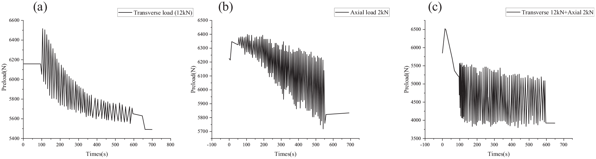
In figure (a), the preload increased first, and then it went down. After the external load was removed, the preload suddenly decreased by 200 N. In figure (b), preload increased first and then decreased, and the stress amplitude increased. In figure (c), preload increased first and then decreased, decreasing by about 2000 N in total.
In addition, the 12 kN and 12 kN-2kN groups show serious embedment on the surface of the CFRP laminate. As shown in Figure 4, the rotation angle of the 12 kN-2kN group is almost the same as that of the 12 kN group, but the embedment is more obvious. This phenomenon is related to the good self-locking characteristics of the jet nut and the low ability of the composite to bear the out of plane load. Due to the obvious preload loss in the 12 kN-2kN group, the influence of preload on loosening is studied by changing preload without changing the loading conditions, as shown in Figure 5. When the preload is 6 kN, the decrease ratio of preload is the largest, which is related to the fact that the CFRP surface is not embedded under this condition, and the embedding occurs only after the cyclic load has appeared. When the preload is 10 kN, the variation range of preload increases with the number of cycles, which is related to the damage extension of composite material. The experimental results show that the initial preload of bolts has no effect on the rotation loosening which is not the main factor in the loss of the preload.

When the preload loss value increase, serious embeddings appear on the composite surface, and the embedding depth was positively correlated with the amplitude of external loading. In figure (a), after applying 6.5 kN preload and then loosening the nut, there was no embedding region on the composite surface. In figure (b), there was an embedding region with uneven depth on the composite surface in the transverse load 12 kN group. In figure (c), there was an obvious embedding region with uneven depth on the composite surface in the transverse load 12 kN and 2 kN axial load group.

The joints with 6, 8, and 10 kN preload subjected to 12 kN transverse cyclic loading and 2 kN axial cyclic loading. The loss of preload in joint with 6 kN preload is the largest, but stress amplitude decreased. The stress amplitude increased in joint with 10 kN.
Results analysis
There are many mechanisms leading to preload loss, such as rotational loosening and fretting wear on the surface of composite materials. The finite element model that considers multiple mechanisms often suffer from difficulties in converge. The test results show that deal to the self-locking nut has a good ability to prevent rotation loosening under the biaxial loading, only a very small rotation of the bolted joints occurs in the initial stage of loading. Therefore, authors believe that the rotation loosening is not the main reason for the preload loss, and the bolt connection model considering the thread requires a lot of computing resources. In the analysis of complex loads, the model is simplified, the thread is ignored and the rotational looseness is not considered. In addition, Figure 5 shows that the preload decreased significantly at the beginning of the test, but slowly in the subsequent loading process. The surface of the composite material is not severely worn, with the effect of fretting wear being ignored in the analysis (Figure 4). Above all, it is considered that embedment may be the main cause of preload loss. In combination with the corresponding finite element analysis method, the coupling mechanism is stripped out. Finally, the relationship between the stress S22 and the embedding depth is established using a combination of test and simulation, in order to obtain the proportion of the embedding looseness in the total preload loss under different loading conditions.
Relationship between stress and embedding depth
Since the permanent embedment of the connected parts will lead to the preload loss, the study of the preload loss caused by the embedment is actually to study the relationship between the load amplitude and the embedding depth of the composite panel. In the experiment, there is no permanent embedment on the surface of the composite panel under the rated preload of the bolted connection, but obvious embedment appears on the surface of the composite material when subjected to biaxial cyclic loading. Due to the uneven embedding depth under biaxial cyclic loading, it is difficult to measure the average embedding depth through experimental results. In another experiment on the relationship between stress and indentation, the author obtained uniform indentation by changing the initial preload, and combined with finite element analysis to obtain a more accurate relationship between stress and embedding depth. Due to the anisotropy of the composite material, the main factor leading to indentation is the out-of-plane stress S22. In this paper, the S22 on the bolt head region is calculated by applying the same preload in the finite element analysis as in the experiment.
The following is a brief introduction to the experiment process and simulation process. In experiment, the preload is applied to the sample, then removing the preload, the thickness of the composite material at the embedding region is measured, and compared with the thickness of the composite material at the no embedding region to obtain the embedding depth. The Abaqus software is used to establish a simulation model. First the 3D solid model of composite panel and bolt for construction are established. After that, the material properties provided by the supplier are input as shown in Table 1. Then the mesh style is set to C3D8R, the mesh density is 0.1 mm. After that the joint is assembled in Abaqus, seeing Figure 6 for the assignment of master surfaces and slave surfaces. In this joint, the tangential behavior of all contact properties used penalty friction behavior with
Properties of HRC1-33%−24KHF10-U-125 gsm-1000 laminate.


The master-slave plane division in finite element model.
The simulation results show that with the increase of the preload, the out-of-plane stress S22 at the embedding region increases significantly. As shown in Figure 7 below, when S22 is 210 MPa, the embedding depth is about 20 μm under the action of 20 kN preload. In order to more accurately express the loss of preload caused by the embedment of CFRP composite material, the relationship between the out-of-plane stress S22 and the embedding depth is established by measuring the average value of stress S22 under different preload in the embedding region of CFRP composite materials. The nonlinear relationship is shown in Figure 8.
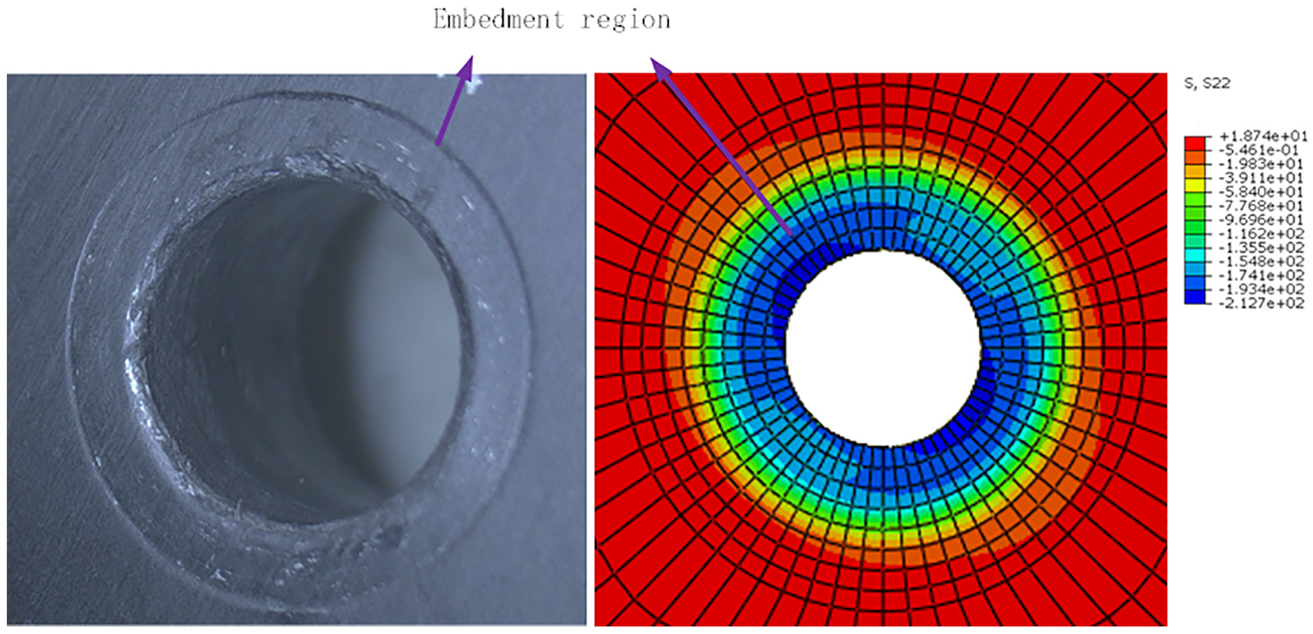
The experiment and simulation result of joint with 20kn preload. When the S22 is 210 MPa, the embedding depth is about 20 μm.

The fitting curve of S22 and embedding depth is
The relation between amplitude of biaxial load and embedding depth
Since the preload loss under biaxial load is caused by multiple factors, in order to understand the influence of the embedment on the preload loss, it is necessary to obtain the proportion of the embedding looseness in the total loss of preload. The uneven embedding region makes it difficult to get the average depth of the embedding experimentally, and the embedment is caused by the stress S22. Therefore, an analytical model is established to calculate the surface stress state of the composite panel, and the average embedding depth is obtained by converting the stress to embedding depth. The simulation model mainly focuses on the stress state when the cyclic load reaches the amplitude. During the analysis, pre-processing development of FEA model is consistent with the above except for the boundary conditions.
In terms of boundary conditions, all the degrees of freedom at one end of the metal material are fixed. In the first analysis step the bolt load is applied to bolt, in the second analysis step a transversal load is applied to one end of the composite material, and in the third analysis step an axial load is applied to the metal panel in the area of bolted connection. The relationship between the average stress in the embedding region and the load amplitude is shown in Figure 9(a). According to the formula obtained in Figure 8, the stress S22 is converted to obtain the embedding depth. From the results in Figure 9(b), it can be seen that the increase of the transversal and axial load significantly increases the stress S22, and when the axial load exceeds 1 kN and the transversal load exceeds 6 kN, embedment appears on the composite surface.

The stress S22: (a) and embedment depth and (b) of the joint with 6 kN preload under different cyclic loads is obtained by finite element simulation.
Proportion of preload loss caused by embedment in total preload loss under external load
As the thickness of the connected part decreases, the change in preload is shown in Figure 10. It can be concluded that the preload caused by embedment can be expressed by Formula (2).
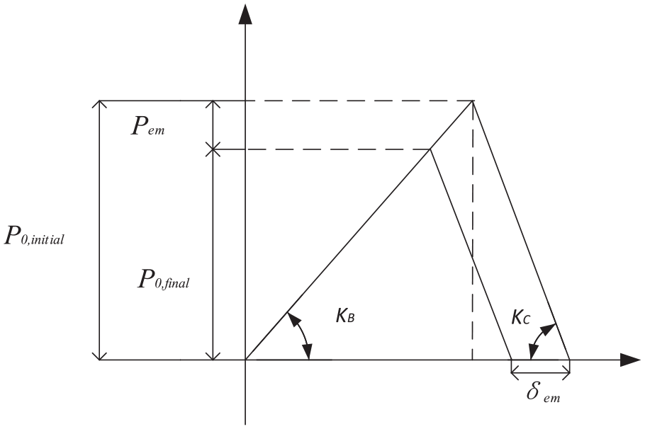
The relationship between Pem and δem in deformation figure.
In Figure 10,


The embedding depth is about 9 μm when the transversal load is 12 kN. According to the calculation result of the above formula, the preload loss caused by the embedment is about 264 N, accounting for 37.3% of the total preload loss 706 N measured by the experiment. When the axial load is applied, the embedding depth is about 8 μm, and the preload loss caused by the embedment is about 235 N, accounting for 59.3% of the total preload loss 396 N measured experimentally. The embedding depth of the bolt is about 18 μm, accounting for 26.9% of the total preload loss 1962 N measured by the experiment. Under biaxial loading, embedding depth increases, and the proportion of preload loss caused by embedment decreases. This phenomenon may be due to the fact that only load amplitude is considered in the embedding studied in this paper, but the embedding depth will increase under cyclic loading, which is related to the cyclic plasticity and fretting wear of the composite material.
Conclusions
This paper mainly designed experiments to analyze the loosening of bolted joints under biaxial loading, and obtained the loosening curve under different biaxial loading.
The experiment results show that compared with uniaxial load, biaxial load can increase the preload loss value, and the change process of preload is related to the initial value. Preload loss value is larger when the initial preload is small. The joints preload loss value up to 1962 N, and embedding depth up to 18 μm with 6 kN initial preload subjected to 12 kN transverse cyclic loading and 2 kN axial cyclic loading. Biaxial loading exacerbates embedment on CFRP laminate surface, accounting for 26.9% of the total preload loss. Therefore, embedding is an important cause of loosening under biaxial loading. Since the self-locking nut has a good ability to prevent rotation loosening under the biaxial loading, there is almost no rotational loosening, other reasons leading to the preload loss may be plastic deformation in the bolt rod and fretting wear of the composite material. In order to prevent the occurrence of preload loss, the hard washer can be used. The hard washer reduces the stress S22 on the composite panel, so that the composite surface does not embed, and the washer will not be embedded in the contact area with the bolt head due to excessive stress. In future research, the proportion of preload loss caused by wear and plastic deformation mechanism under biaxial load can be analyzed, and the influence of different washers and composite strengthening technologies around the hole on the preload reduction caused by embedding can be studied, and a better anti-loosening method can be proposed based on the mechanism of preload reduction.
Footnotes
Handling Editor: Chenhui Liang
Declaration of conflicting interests
The author(s) declared no potential conflicts of interest with respect to the research, authorship, and/or publication of this article.
Funding
The author(s) disclosed receipt of the following financial support for the research, authorship, and/or publication of this article: This work was supported by the National Natural Science Foundation of China (51975280).