
Abstract
In practice, vibrations in the turbine inlet valves can develop flow rate and pressure fluctuations in the penstocks of the hydropower plants that can risk the safe operation of the power plant. Accordingly, this study has two aims: the first aim is to explain and simulate the valve’s periodic vibrations while considering the power plant’s relevant physical and geometrical parameters. The second aim is to provide recommendations to improve the dynamic stability of the valve’s vibrations. The theoretical model developed to explain the phenomenon comprises the nonlinear unsteady energy equations representing the fluid flow at the pipelines, the continuity equation modelling fluid flow through different junctions, and the valve’s seal equation of motion to compute the valve’s vibrations. The system governing equations are solved nonlinearly using the MATLAB toolbox SIMULINK. The study demonstrated that the origin of the valve’s vibrations is the leakage of the valve’s service seal. The presented model results exhibited that the unstable valve vibrations (of increasing amplitudes) are more prone to occur at higher input reservoir energy levels. Also, installing a valve that can be closed to a certain degree at the pilot pipeline can enhance the dynamic stability of the valve’s vibrations.
Introduction
Since hydropower plants have a considerable share of 16% in electricity production globally, 1 maintaining the reliable and safe operation of the power plant is substantial. Basically, a hydropower plant comprises a reservoir, penstocks, turbine inlet valves, drive shafts connecting the turbines to the generators for electricity production, and a draft tube, as in the case of the Salime power plant. The Salime power plant located at the Southwest of the principality of Asturias, on the Navia River, Spain 2 consists of four Francis turbines with 105 m nominal head and a combined flow rate of 170 m3/s. Each turbine has a rated power output of 40 MW. Also, each unit has its own penstock of 80 m long with a butterfly valve installed at the penstock entrance and a turbine inlet valve (TIV) at the downstream side of the penstock as in Figure 1(a).

(a) Description of the Salime power plant, (b) turbine inlet valve (TIV) (spherical valve) in closed position and (c) explanation of the sliding service seal operation.
The turbine inlet valve (TIV) under operation is not intended to regulate the flow through the turbine but to block the water flow to the turbine when the production stops as in Figure 1(b). The (TIV) installed at the Salime plant is a spherical valve that consists of a ball with a bore in the middle and two metal annular seals as in Figure 1(b). The first seal is the maintenance seal, which operates manually to provide extra water tightness when the service seal malfunctions. While, the second seal is the service seal responsible for the sealing operation when the ball valve is closed and the turbine is in no-load condition.
In normal conditions, when the valve is in a closed position, the water flow passes through the pilot pipeline and pushes the service seal to slide towards its seat on the ball surface as in Figure 1(a) and (b). This seal movement closes the clearance between the ball surface and the valve casing, preventing any leakage flow through the valve. However, in practice, while the turbine is not operating and the valve is closed, the service seal did not stay on its seat on the ball surface; instead, it started to generate periodic vibrations. These vibrations were noticed as internal violent impacts accompanied by pressure oscillations in the piping system of the hydropower plant.
One solution to this problem was closing the butterfly valve at the penstock entrance, particularly, when the pressure values exceeded the security limit established at 13.5 bar as in Figure 2.

Penstock pressure signal recorded at the upstream side of the (TIV) during a vibratory episode of the valve of unit #3. 3
In fact, this solution was feasible since the pressure fluctuations were damped reaching their steady state values as in Figure 2, though, this procedure was not favourable for the power plant managers for the following reasons: First, there was a high water leak; second, the subsequent start-up operation of the turbines was very complex; and finally, there were no more security measures to be considered for other unexpected events. In order to overcome these problems, another solution was introduced, which was applying an auxiliary compressed air system to the pilot pipeline. The aim of this auxiliary system is to increase the pressure forces acting on the seal to prevent leakage flow when the valve closes. This was an effective solution as it eliminated the seal vibrations. However, the vibrations event may regenerate if there is a problem within the compressed air system, or if there is a lag between the valve closure and the operation of the auxiliary system.
Based on the information gained from the plant, since there is no external force acting on the seal that may lead to the seal vibration, it is expected that the seal vibrations are self-excited due to the existence of an unsteady leakage flow between the seal and the ball surface. Indeed, the problem of (TIV) vibrations has been noticed in several power plants since a long time ago, though the cases reported in the literature are very rare; for example, Abbott et al. 4 in 1963 reported the vibration problem of the Bersimis hydropower plant at Niagara Falls, USA. As in the present case for the Salime power plant, large pressure oscillations were observed in the penstock while the spherical valve was closed. The reason behind these pressure fluctuations was the slight leakage of the inflatable service seal due to the lack of pressure forces acting on the seal. Wylie and Streeter 5 in 1965 continued the investigation of Abbott et al. 4 on the vibration phenomenon at the Bersimis power plant. The analysis of the system was accomplished by applying the impedance method as well as the method of characteristics. The computed results of the pressure oscillations agreed with the experimental results. These results confirmed that the leakage flow through the (TIV) was the main reason for the development of these vibrations and pressure oscillations. Gummer 6 in 1995 reported on severe penstock pressure surges during priming and load rejection at the unit G1 of the Maraetai No.1 hydropower plant (New Zealand). Similarly, the origin of these pressure surges was the leakage of the intake valve. However, in this case, the valve was a head gate. Furthermore, Caney and Zulovic 7 in 2004 and Kube et al. 8 in 2010 studied the penstock resonance phenomenon at the Gordon Power Station (Australia) using a commercial software called ‘Hytra Solution’. The software applies the principles of the impedance method and the method of characteristics. Likewise, system analysis demonstrated that the penstock resonance occurred due to the seal leakage in the (TIV), which was also a spherical valve. The software results exhibited that the impedance results can predict the pressure oscillation frequency, although, the software could not compute the realistic values of the pressure fluctuations because the dynamic seal characteristics were neglected in the analysis. Finally, based on the study for the Bersimis plant,4,5 Chaudhry 9 in 2014 compared the conditions of the leaking system leading to valve instability utilising a leakage flow velocity diagram. For a normal stable valve, it is noticed that a system disturbance developed by varying the leakage flow velocity will decay over time until returning to steady-state conditions. In contrast, a system disturbance is amplified overtime for a leaking valve.
The problem of self-excited oscillations in hydropower plants with leaking valves can be compared to similar processes in other types of valves that operate at small openings, for which there is more scientific literature. A common feature for the instability to establish is that the valve’s obstructing element and the fluid system, when set into oscillatory motion, couple in a way that the resulting dynamic forces provoke the motion of the valve’s element. Therefore, a continuous supply of fluid energy to the structure is maintained leading to valve instability such as in the cases of Wang et al., 10 Allison et al., 11 Peng et al., 12 El Bouzidi et al., 13 Ma et al. 14 and Jia et al. 15
According to the mentioned studies, (TIV) vibration is a serious problem since it can risk the safe operation of the power plant. In consequence, the first aim of this study is to develop a theoretical model that can explain the excitation mechanism and simulate the seal’s periodic vibrations while considering the dynamic seal characteristics, the unsteady nonlinear hydraulic losses, and the power plant relevant data. Afterwards, an evaluation phase for different system configurations will proceed in order to yield some recommendations for improving the (TIV) dynamic performance related to the seal’s periodic vibrations. Finally, this study serves the sustainable development goals as the outcomes of this study can extend the lifetime of the power plant as well as improve the manufacture of the turbine inlet valve.
Theoretical model
Preliminary evaluation of the case study to guide in model construction
To explain the phenomenon of the TIV vibration; the theoretical model developed is based on the hypotheses of having an unsteady leakage flow between the valve’s service seal and the ball surface as there was no external force to excite the seal oscillations. This type of vibration is related to the movement-induced excitation (MIE) flow induced vibrations 16 where the seal vibrations are said to be self-excited. For the case under consideration, if the seal is subjected to a disturbance, the seal clearance will vary as well as the flow rate through the seal clearance. In this situation, the pressure changes on both sides of the seal. As a result, the fluid force acting on the seal changes and the seal starts to develop periodic vibrations due to the seal structure elasticity. At this point, as the seal and the fluid system are set into oscillatory motion, they couple in such a way that the fluid system becomes the source of energy for the seal motion. If the energy supplied by the fluid system exceeds the system’s dissipation energy, presented in the system hydraulic losses and the seal structure damping, the system will be dynamically unstable. In this case, the amplitude of both the seal oscillations and the pressure fluctuations increase till reaching the limit cycle oscillations when the dissipation energy becomes the same as the energy supplied by the fluid system.
To make the theoretical model as simple as possible whilst including all the relevant plant data, it was decided to consider both the spherical valve scheme of Figure 3(a) and the hydro-mechanical model representing each group of the Salime power plant as in Figure 3(b). The relative positions and dimensions of the presented system are identified as in Table 1.

(a) Closed spherical valve with relevant sections numbering and (b) hydro-mechanical model with sections numbering for each group of the Salime power plant.
Relative positions and dimensions of the Salime power plant hydro-mechanical model.

According to the mechanism of the seal excitation, the theoretical model computes the dynamic seal behaviour in two steps. The first step concerns the computation of the fluid dynamic force acting on the seal while the second step is the seal’s periodic vibration computation from the seal equation of motion.
Computation of the fluid dynamic force acting on the seal
According to Figure 3(a) and (b), two types of equations are used to compute the fluid pressure force acting on the seal. For the pipelines, the unsteady energy equation for an unsteady, unidirectional, incompressible, and viscous flow 17 is applied. While for the different junctions, the continuity equation 18 is used. For a pipeline j as in Figure 3(b), the unsteady energy equation is calculated as follows.

Hei and Hei + 1 are the energy heads at the upstream and downstream sides of a pipeline j; Lj and Aj are the length and cross-section area of pipeline j; and Kj is the hydraulic resistance for the pipeline j, which includes the pipeline friction losses and the pipeline minor losses. 18 Since Kj varies according to pipeline type of flow and minor losses, each pipeline hydraulic resistance presented in Figure 3(b) is computed as follows.

fj is the friction factor at pipeline j; dj is the pipeline j diameter; Ag is the gap cross-section area

KLd is the minor loss coefficient of the pilot pipeline d. KLd is used only to evaluate the influence of changing the pilot pipeline head losses on the dynamic behaviour of the seal; other than that the
To determine the flow rate passing through the junction at Section 2 and through the seal gap, see Figure 3(b), the continuity equation is applied as follows.
Section 2:

flow rate through the gap:

By applying the mentioned equations, the fluid pressure force acting on the seal can be determined as:

where,

(TIV) service seal specifications: (a) service seal section view, (b) un-deformed service seal side view with dimensions in mm and (c) deformed service seal side view with maximum clearance position.
Finally, to keep the theoretical model as simple as possible while considering the main features of the vibration phenomenon, the interaction between the leakage flow and the turbine is neglected since the energy loss occurs mainly at the TIV.
Seal equation of motion
As mentioned in the introduction section, the reason behind the seal’s periodic vibrations as well as the penstock pressure oscillations is the clearance that exists between the service seal and the ball surface. This clearance may exist because of the following reasons: (1) lack of pressure forces acting on the seal, (2) manufacturing imperfection or (3) inappropriate assembly. According to the seal structure, it is expected that one portion of the seal will stick to the ball surface while the other portion will deflect from the ball surface, as in Figure 4.
In order to compute the (TIV) vibrations related to the seal’s periodic vibration, the seal structure mass, stiffness and damping coefficients corresponding to the clearance circumference length Lo must be computed first. Therefore, the service seal structure coefficients computation is performed as in Awad and Parrondo, 19 where an average seal clearance thickness and mean seal vibration displacement are considered.
Once the fluid force acting on the seal is computed the seal periodic vibrations can be computed using the seal equation of motion 20 as follows:

θg is the gap angle, which is the angle corresponding to the clearance circumference length Lo
Theoretical model computation
The system governing equations are mainly nonlinear ordinary differential equations as in equations (1), (4) and (5). To solve the system governing equations a MATLAB code is constructed using the toolbox SIMULINK. The SIMULINK solver used is ODE 45 based on the Runge Kutta method with a variable time step. To solve the system equations using ODE 45, the initial values of the system variables are required since the problem is an initial value problem. Therefore, the initial values of the system variables are inserted as their steady-state values. The computer code is constrained to simulate the problem with a maximum time step of 10−3. Besides, the solution convergence is achieved when the relative tolerance is below 10−3. The full version of the Simulink code comprising the whole system’s governing equations is mentioned in the Appendix from Figure A1 to Figure A13.
Results and discussion
At the Salime power plant, the (TIV) seal vibrations result in pressure fluctuations in the penstock pipeline that can exceed the penstock’s pressure security limit established at 13.5 bar. If no security measures are taken, these pressure oscillations can lead to catastrophic events such as penstock rupture and powerhouse submergence, which is not acceptable. Consequently, the discussion and result section is split into two parts: the first part concerns answering the following questions; what is the origin of the seal vibration?, what causes seal vibration instability (seal vibration of increasing amplitude)? and how does the seal vibration influence the penstock pressure fluctuations?
The second part of the results presents a parametric study where the vibration phenomenon is evaluated under different system configurations to provide recommendations for enhancing the dynamic stability of the (TIV) vibrations as well as the penstock’s pressure oscillations. The parameters selected for the study are selected according to the following methodology: factors related to the seal characteristics, such as seal dimension and materials, and factors applicable to be modified in the power plant, such as pilot pipeline dimensions and hydraulic losses.
Seal periodic vibrations
Figure 5 shows the dynamic behaviours of the periodic seal vibration displacement y, the fluid dynamic force acting on the seal F and the penstock pressure oscillations in Section 2 P2 at the upstream side of the (TIV), see Figure 3(b). These three parameters are computed for three cases where the gap angle θg and the input reservoir energy level H1 are varied. Figure 5 demonstrates that the fluid dynamic force depends on the seal oscillatory motion, as seen in all of the three cases. This behaviour confirms that the seal vibrations are self-excited and the origin of the seal’s vibration is the existence of an unsteady leakage flow. In this situation, when there is a gap between the seal and the ball of the (TIV), and the seal is subjected to a disturbance, the leakage flow varies beneath the seal as well as the fluid force acting on the seal. As a result, the seal starts to develop periodic vibrations because of the seal structure elasticity, such as in Figure 5.

(a) Dynamically stable system H1 = 25 m, θg = 30° and f = 28.6 Hz, (b) critical stable system H1 = 55 m, θg = 40° and f = 13.9 Hz and (c) dynamically unstable system H1 = 90 m, θg = 32° and f = 26.2 Hz.
The energy transfer from the fluid system to the seal structure depends on the fluid force acting on the seal. Therefore, the seal may develop three different dynamic behaviours depending on the amount of energy transferred from the fluid system to the seal structure. Firstly, if the seal’s structure damping and the fluid system hydraulic losses, representing the dissipated energy by the system, exceed the energy transferred by the fluid system, the seal vibrations damp over time. In this case, the system is said to be dynamically stable as in Figure 5(a). Secondly, if the energy transferred by the fluid system is the same as the dissipated energy, thus the system is critically stable. In this situation, the seal vibrations are maintained but at constant amplitude, as in Figure 5(b). Thirdly, if the dissipation energy is lower than the energy transferred to the seal structure, the seal vibrates with increasing amplitude over time till hitting the ball surface at a hitting time th, as in Figure 5(c). In this case, the system is dynamically unstable because the pressure oscillations increase over time exceeding the penstock’s pressure security limit as in Figure 5(c), risking the safe operation of the power plant. Finally, comparing the results of the penstock pressure oscillations in Figure 5(c) with that in Figure 2 reveals that the simplified theoretical model can compute the penstock’s steady-state pressure value at 9 bar as well as the penstock’s pressure oscillations. If the system is dynamically unstable, these pressure oscillations reach the established security limit as in Figures 2 and 5(c). Also, they can exceed the established security limit at 13.5 bar if no security actions are taken, as in Figure 5(c). On the other hand, the calculated pressure oscillation frequency cannot be compared to that in Figure 2 because the data acquisition system available at the Salime plant, during this occasion, allows registering only one data per second. Thus, the signal quality is too poor to attempt a proper dynamic analysis.
According to the power plant load demands and maintenance operations, the turbine shut down as well as the valve closure can be operated at different input reservoir energy levels. During the valve closure operation if there is a lack of pressure forces acting on the seal, the gap angle between the seal and the ball surface is obscure. Therefore, the influence of the input reservoir energy level and the seal gap angle on the dynamic seal behaviour is assessed, as in Figure 6, as they significantly influence the seal’s periodic vibrations as in Figure 5.

Influence of H1 on the: (a) seal hitting time th, (b) seal’s clearance thickness yog and (c) seal’s oscillation frequency f. ksg = 1.62, 2.22, 3.17, 4.73, 7.51 and 12.9 MN/m at θg = 50°, 45°, 40°, 35°, 30°and 25°, respectively.
The hitting time th can identify the power plant dynamic behaviour related to the seal’s periodic vibrations. If the periodic seal vibrations are dynamically stable, the hitting time is zero since both the seal’s vibration displacement and the pressure oscillations damp over time. In contrast, if the seal’s dynamic behaviour is unstable, as in Figure 5(c), the hitting time will be the time needed by the seal oscillations to hit the ball surface as in Figures 5(c) and 6(a). The hitting time th can evaluate also the influence of H1 and θg on the amount of energy transferred from the fluid system to the seal structure. If th is of decreasing value but greater than 0, this means that the amount of energy transferred to the seal structure increases as the time needed by the seal oscillations to hit the ball surfaces decreases.
Figure 6(a) exhibits that for a constant gap angle, increasing H1 increases the energy transferred to the seal structure since the unstable seal vibrations (i.e. th > 0) are more often to occur at higher H1 values. In addition, the seal hits the ball surface faster at higher H1 since the energy transferred to the seal structure increases while the gap thickness yog between the seal and the ball surface decreases, as in Figure 6(a) and (b). Similarly, Figure 6(a) shows that the seal’s periodic vibrations are more prone to be dynamically unstable at higher θg as increasing the gap angle decreases the input reservoir energy level required for the seal to be dynamically unstable. In addition, the seal hitting time reduces by increasing θg because the unsteady leakage flow increases, increasing the amount of energy transferred to the seal structure, while both the gap thickness yog and the seal structure stiffness ksg decrease due to the reduction of the seal structure stiffness. Finally, the frequency of the seal oscillation is mainly influenced by the seal gap angle, as in Figure 6(c), since the seal structure stiffness decreases greatly by increasing θg. As a result, increasing the gap angle decreases the frequency of the seal oscillation, as in Figure 6(c).
Parametric study
Figure 7 shows the influence of the pilot pipeline geometry and hydraulic losses on the dynamic seal behaviour at H1 = 150 m and θg = 50° representing the worst seal dynamic behaviour as in Figure 6(a). Figure 7(a) demonstrates that for all pilot pipeline lengths, decreasing the pilot pipeline diameter enhances the dynamic behaviour of the seal since th reaches 0 at small values of dc. On the other hand, shortening the pilot pipeline length risks the system dynamic stability since th decreases at the same value of dc; such as at dc = 20 mm, the th values are 1.27, 3.92, 7.28, 11.54 and 17.1 for Lc = 5, 15, 25, 35 and 45 respectively. Thus, a smaller dc is needed for shorter pilot pipelines to maintain a stable periodic seal vibrations (i.e. th = 0) as in Figure 7(a).
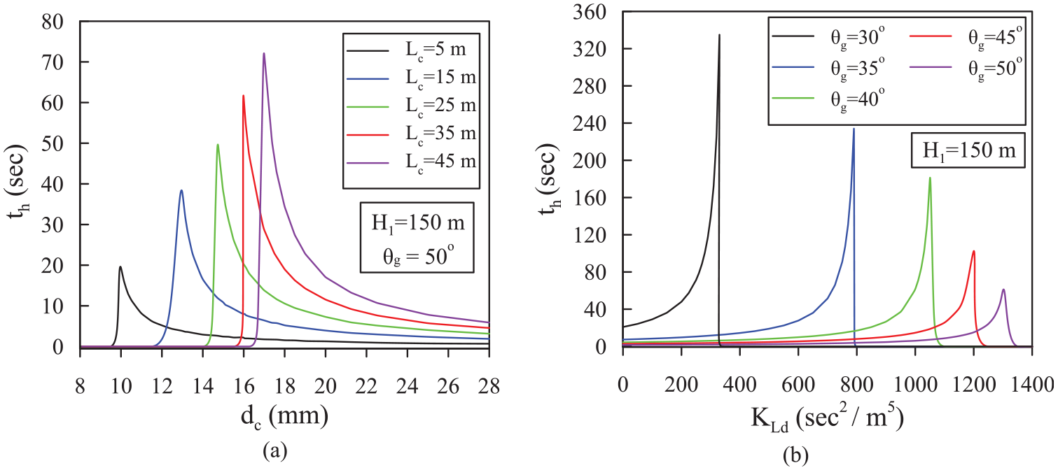
Influence of: (a) pilot pipeline geometry and (b) hydraulic losses on the seal’s hitting time th.
To evaluate the influence of the pilot pipeline hydraulic losses on the dynamic seal behaviour without changing the pilot pipeline dimensions; the pipeline head losses are changed by varying the pipeline minor losses coefficient KLd as in Figure 7(b). By increasing the pilot pipeline losses (i.e. by increasing KLd), the energy dissipated by the fluid system exceeds the amount of energy transferred to the seal structure. As a result, at high values of KLd, the seal’s periodic vibrations damp over time, leading to a dynamically stable system (i.e. th = 0) as in Figure 7(b).
Figure 8 shows the influence of the seal geometry on the seal’s behaviour. The seal’s geometry influence is evaluated by changing the surface area of the seal facing the gap flow Ass as well as the surface area facing the water pressure passing through the pilot pipeline Aos. According to the seal’s dynamic behaviour, Figure 8(a) demonstrates that the seal geometry has a minimal influence on the seal’s periodic vibrations since the variation of the seal hitting time is very small (i.e. the same goes for varying Ass). Therefore, the periodic vibration of the seal is almost the same even at different seal geometries since the amount of energy transferred to the seal results in nearly the same th.

Influence of the seal surface areas Aos and Ass on: (a) th at H1 = 150 m and θg = 50° and (b) yog and Qog at θg = 50°.
On the other hand, although the seal’s geometry has a negligible influence on the dynamic seal behaviour, it has a significant effect on the reason provoking the seal’s periodic vibrations, which is the seal clearance developing the leakage flow. Figure 8(b) exhibits how the seal geometry influences the seal clearance and the gap flow rate using the parameter γ, which represents the ratio between both surface areas of the seal
To evaluate the influence of the seal material on the dynamic behaviour of the seal, the seal hitting time is computed at: different input reservoir energy levels H1 = 5–150 m, constant gap angle θg = 50° and pilot pipeline geometry dd = 30 mm and Ld = 15 m, and for four different seal materials 21 as in Figure 9. The seal’s materials properties are mentioned in Table 2.

Effect of the seal structure material on: (a) th, (b) f and (c) yog. θg = 50°, dc = 30 mm, and Lc = 15 m.
Seal’s material properties. 21

As seen in Figure 9(a), the seal material has a negligible influence on the dynamic stability of the seal’s vibration since the seal hitting time, th > 0, starts at nearly the same input reservoir energy level H1 = 10 m. In contrast, the seal material affects significantly the seal’s oscillation frequency and static stability condition (i.e. yog = 0). In which, selecting a material with a high modulus of elasticity E, such as Aluminium oxide 96% pure, increases the seal structure stiffness. As a result, the seal’s oscillation frequency f as well as the seal clearance thickness yog increases as in Figure 9(b) and (c). Therefore, selecting a material of lower modulus of elasticity is better as the full closure of the seal clearance can be established at a lower input reservoir energy level, particularly since the dynamic stability of the seal oscillations is negligibly influenced by the seal material.
Conclusion
The developed study demonstrated the significance of studying the turbine inlet valve vibrations as it may lead to pressure oscillations in the pipelines exceeding the established security limit, leading to catastrophic events such as penstock rupture. The presented simplified theoretical model has the ability to develop the Turbine inlet valve’s vibration as well as the penstock’s pressure oscillations related to the valve’s vibrations. The theoretical model confirmed that the valve vibrations are self-excited due to the presence of an unsteady leakage flow between the valve’s seal and the ball surface. In this case, the fluid system is the energy source for the (TIV) vibrations related to the seal’s periodic oscillations. So even if the seal is under equilibrium a seal disturbance may lead to pressure and flow rate fluctuations of decaying or diverging amplitudes depending on the seal’s dynamic stability. After evaluating the dynamic seal behaviour under different system configurations; the following points can be concluded:
1- The unstable behaviour of both the seal’s periodic vibrations and the penstock’s pressure oscillations are more prone to occur at higher input reservoir energy levels and wider seal’s gap angle.
2- The dynamic stability of the seal’s periodic vibrations as well as the penstock pressure fluctuations can be enhanced by decreasing the diameter and increasing the length of the pilot pipeline.
3- Increasing the hydraulic losses of the pilot pipeline, such as by installing a valve to the pipeline that can be closed to a certain degree, can eliminate both the seal’s periodic oscillations and the related penstock pressure fluctuations.
4- The geometry and the material of the seal showed a minimal influence on the dynamic stability of the seal’s periodic vibrations. However, they can reduce significantly the clearance between the seal and the ball surface, the origin of the seal’s periodic vibration. Increasing the seal’s surface area facing the pilot pipeline and selecting a seal material of low modulus of elasticity can achieve full seal closure at lower input reservoir energy levels.
5- The frequency of the seal’s oscillation increases by increasing the seal’s gap angle and the seal’s material modulus of elasticity due to the seal structure stiffness increment. In contrast, the input reservoir energy level has a negligible influence on the seal’s oscillation frequency.
6- Finally, if the system is dynamically unstable, the seal oscillations increase till hitting the ball surface since the seal clearance is small. Therefore, the limit time cycle oscillations are not established and solving the system’s governing equations linearly is appropriate.
Footnotes
Appendix
The Simulink diagrams of the system governing equations are presented in Figures A1–A13, as follows:
Handling Editor: Chenhui Liang
Declaration of conflicting interests
The author(s) declared no potential conflicts of interest with respect to the research, authorship, and/or publication of this article.
Funding
The author(s) received no financial support for the research, authorship, and/or publication of this article.