
Abstract
Elliptical gear is a common type of non-circular gear; it’s theory and design methods are mature. But the research on denatured elliptical gear was not enough, the design method of tooth profile was single, low precision, and there may occur tooth overlap at the splice when the denatured elliptical gear is generated by the envelope method. The denatured elliptical gear design in the existing literature did not include tooth profile point extraction, so the denatured elliptical gear design only exists in theory, it can’t obtain the necessary data for processing and production. Given this situation, a design method is proposed to design denatured elliptical gear, and the tooth profile data are extracted. The main steps are as follows: firstly, the arc length of gear was calculated, and the arc length corresponding to the rotation angle is obtained. The piecewise interpolation of the gear with equal arc length was spliced together to get a complete envelope image, then, the image was binary processed. Finally, using the designed program, the tooth profile pixels were extracted by the eight-neighborhood algorithm. This method provides a new way of designing denatured elliptical gear, this method is stable and has a fast operation speed. The tooth profile data can be directly used for 3D modeling or wire cutting machining.
Non-circular gear can achieve a stable variable transmission ratio transmission, it has high efficiency and good stability, playing an indispensable role in the mechanical transmission area, such as rice transplanters and fertilizer machines.1–5 In recent years, plenty of research on non-circular gear had done, especially in elliptical gear; elliptical gear has a mature design theory. The mathematical model of non-circular gear hobbing6–8 or non-circular gear shaping9–11 is established, different interpolation algorithms12,13 are studied, the tooth profile were extracted by the numerical algorithm,14–16 and research directly uses the analytic method17,18 to design elliptical gear and high order elliptical gear.5,19
The design methods for denatured elliptical gear are relatively single, Da-wei and Ting-zhi 20 used a numerical calculation method to solve the pitch curve of denatured elliptical gear according to the transmission ratio curve of the driven gear. Xia et al 21 used an analytical method with MATLAB and VBA mixed programing to achieve the design of variable elliptical gear. Qiu and Deng 22 designed a denatured elliptical gear with the conversion method of tooth profile. Liu et al. 23 used the conversion method tooth profile to create denatured elliptical gear and analyzed its kinematics. Although some research on the design of the denatured elliptical gear, how to extract tooth profile data is not mentioned. The tooth profile data is necessary for the machining, without which it is impossible to generate or even manufacture 2-D denatured elliptical gears. However, the methods to extract tooth profile data are not discussed in the above methods.
For the above deficiencies, this paper focuses on the design of denatured elliptical gear and extraction of tooth profile data. It mainly solves the arc length of the denatured elliptical gear and the corresponding relationship between the arc length and rotation angle. Based on the original foundation, the splicing denatured elliptical gears are optimized to solve the overlapping of envelope tooth shape at the splice. Finally, based on the conjugate forming process of gear pair, and combined with the relevant theory of image edge pixel extraction in computer graphics, the edge profile of non-circular gear is extracted by boundary tracking algorithm; and then the precision analysis is carried out.
Pitch curves and parameter design of denatured elliptical gear
Pitch curves of denatured elliptical gear
The pitch curves of denatured elliptical gears are closed nodal curves consisting of several elliptical nodal curves in a certain order. Among them, the most common one is the two-stage denatured elliptical gear; two driving pitch curve equations are as follows.

The nodal curve equations of the driven wheel meshing with the driving wheel are,

where

The total length of the nodal curve
The total length of the nodal curve of the driving wheel can be expressed as:

The total length of the driving wheel nodal curve is
Radius of curvature
As the pitch curve equation of a non-circular gear is

where
Under the condition that no undercut occurs, the value range of the modulus is
where
Design of denatured elliptical gear with piecewise merging
Basic parameters of the case
The design process of a denatured elliptical gear
24
is illustrated in the following case. The basic parameters
25
of a denatured elliptical gear pair are as follows:
The solution process is shown in the following steps. Based on the center distance

The nodal curve equations of the driven wheel are obtained as:
Substitute the data into equation (4), get the integral function
The diagram of
The Trapezoidal numerical integration method is used to calculate the relation curve of
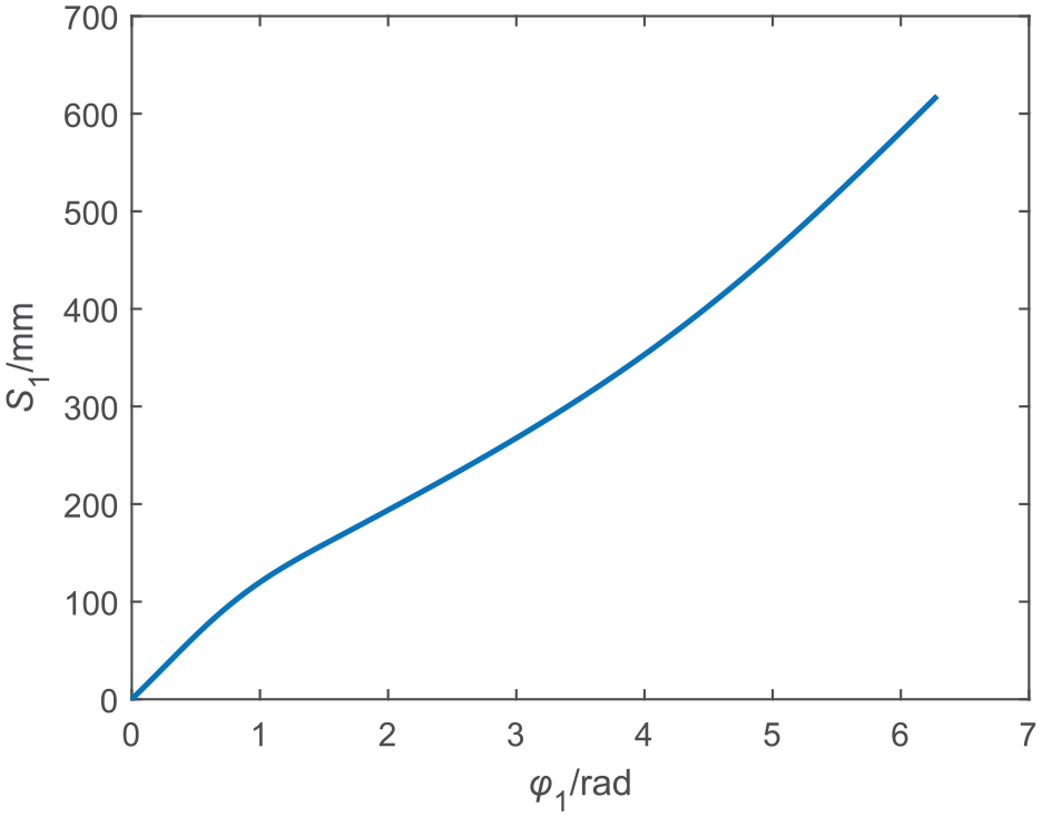
The relationship between angle and arc length.
Based on equations (8) and (9), the nodal curves of the driving and driven wheel can be obtained, as shown in Figure 3.

Pitch curve of the driving and driven wheel.
Design denatured elliptical gear with piecewise merging
The nodal curve of the driving wheel consists of two section curves, as shown in Figure 4.

Pitch curve of the driving wheel.
A denatured elliptical gear can be thought of splicing two parts together; in the use of gear shaper envelope will appear tooth overlap and cross at the splice, causing errors. There are two solutions to this problem. One is to change the distance of the normal equal distance curve of the denatured elliptical gear pitch curve; the disadvantage of this method is that it requires trial and error. The second method is to optimize the envelope process of denatured elliptical gear; the advantage of this method is high efficiency. This article chooses the second method.
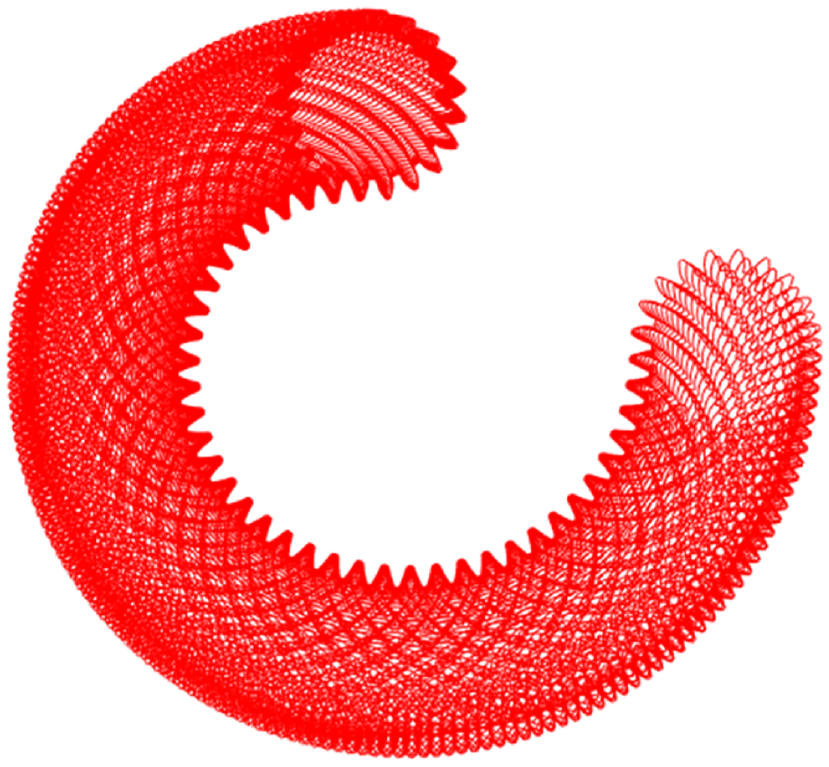
According to the basic principle of gear processing, a complete envelope tooth profile can be obtained by rolling the pitch circle of a circular gear cutter along the pitch curve of the processed gear. Then, the first segment curve and the second segment curve were processed by equal arc length gear shaping. Figure 5 shows the interpolation process of the first segment curve of the driving wheel; Figure 6 shows the interpolation process of the second segment curve of the driving wheel.

The first segment curve of the driving wheel.
The second segment curve of the driving wheel.
The complete envelope image of the driving wheel is obtained by combining the two machining processes, as shown in Figure 7(a). Use the same method, the image of the driven wheel is obtained, as shown in Figure 7(b). The local enlargement image is shown in Figure 8, analyze Figure 8, there is no overlap and cross of envelope tooth shape at the splice, proving the correctness of the method; it also provides the basis for the extraction of tooth profile.

Optimized complete envelope image of the driving and driven wheel: (a) the driving wheel and (b) driven wheel.

Partial enlarged image of the driving and driven wheel after optimization: (a) the driving wheel and (b) driven wheel.
If use the old method, namely equal polar angle method, the envelope image is directly formed according to the rotational angle of the gear shape envelope, then, the two pieces of the denatured elliptical gear are joined together, as shown in Figure 9. The local enlargement image is shown in Figure 10, overlap and cross of envelope teeth occur at the splice, which caused the error of the tooth profile point extraction in the latter.

Complete envelope image of the driving and driven wheel before optimization: (a) the driving wheel and (b) driven wheel.
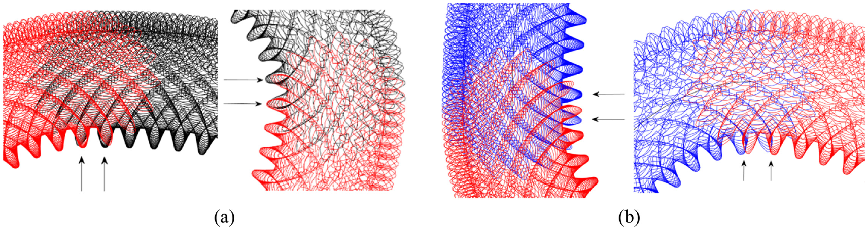
Partial enlarged image of the driving and driven wheel before optimization: (a) the driving wheel and (b) driven wheel.
There are many factors to be considered in the design of denatured elliptical gears. To clarify the design process more clearly, this paper gives the following steps.
(1) Solve
(2) Solve pitch curve equations of the driving and driven wheel, to obtain the initial rotation position of the denatured elliptical gear pair.
(3) Solve the maximum modulus of the denatured elliptical gear, solve the minimum tooth number of the driving and driven wheel without undercutting, and determine the tooth number and modulus of the denatured elliptical gear based on the formula
(4) Perform the undercutting test, pitch curve closed test, and convexity test.
(5) Calculate the relationship between the rotation angle and the arc length of the pitch curve.
(6) Determine the parameters of the gear shaper cutter, solve the center path of the gear shaper cutter, and design the tooth profile of the gear shaper cutter.
(7) Apply the method of equal arc length to form the first section of the envelope tooth profile, and adjust the angle and position of the gear shaper cutter to form the second section of the envelope tooth profile. Then form the envelope tooth profile of the denatured elliptical gear by splicing two sections, and check whether there is tooth overlap and crossover at the splice.
(8) Design completed.
Extraction of tooth profile data
The envelope image is processed by binarization
The complete envelope image is obtained; the number of pixels per unit length is set according to the required accuracy. Then, read the picture through MATLAB software, the binarization process26,27 is carried out, and the binary image is shown in Figure 11. After the binarization process, the whole picture consists of two elements, 0 and 1, the white part is all 1, and the black part is all 0.

Binary image.
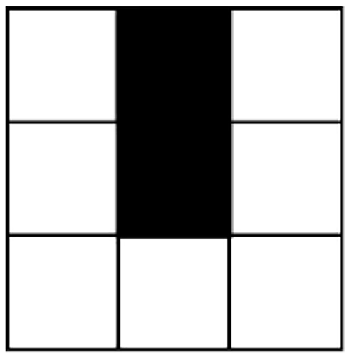
Determine the starting point for eight-neighborhood algorithm
Firstly, the size rows × columns of the pixel matrix in the binary image are determined; find the pixel in the center (rows/2, columns/2) of the pixel matrix, and make these two values an integer. Then, the first black pixel with a value of 0 is denoted as
Search mechanism
The search mechanism is from the starting boundary point to the correct tracking of the next boundary pixel until all the boundary pixels of the target are extracted. When centered at

The coordinate diagram of the starting pixel and the surrounding pixels.
Regard point

The direction of the pixel is searched for the first time.
According to the above operation, get the
In the first case,

The first kind of position relation between the point and the center point.
In the second case,

The second kind of position relation between the point and the center point.
In the third case,
The third kind of position relation between the point and the center point.
In the fourth case,
The fourth kind of position relation between the point and the center point.
According to four different position relations of

Four different search methods: (a) top right, (b) lower left, (c) lower right and (d) top left.
Stopping criterion
Loop through the operations of section “Search mechanism” the loop ends when the search reaches the starting point again, indicating that the entire boundary pixel tracking is completed. The following is the process of eight-neighborhood algorithm.
(1) Determine the search starting point of the tooth profile pixel denoted as
(2) Use the “top right” search method to find the first black pixel
(3) If the point
(4) Judge the position relationship between
(5) Search closure.
The extracted pixels are converted into actual data points
Since this method extracts pixels in the image, but the number of pixels on the vertical and horizontal axes are integers, if the position of the extracted pixel is directly output as the horizontal and vertical coordinates, it is essentially enlarging the image. And the more pixels are set during the image output, the larger magnification of the image. So, the first step is to determine the magnification of the image relative to the original image, and restore the image to the original standard size data.28,29
Assume that Figure 19 is the exported image, the actual length of the image is

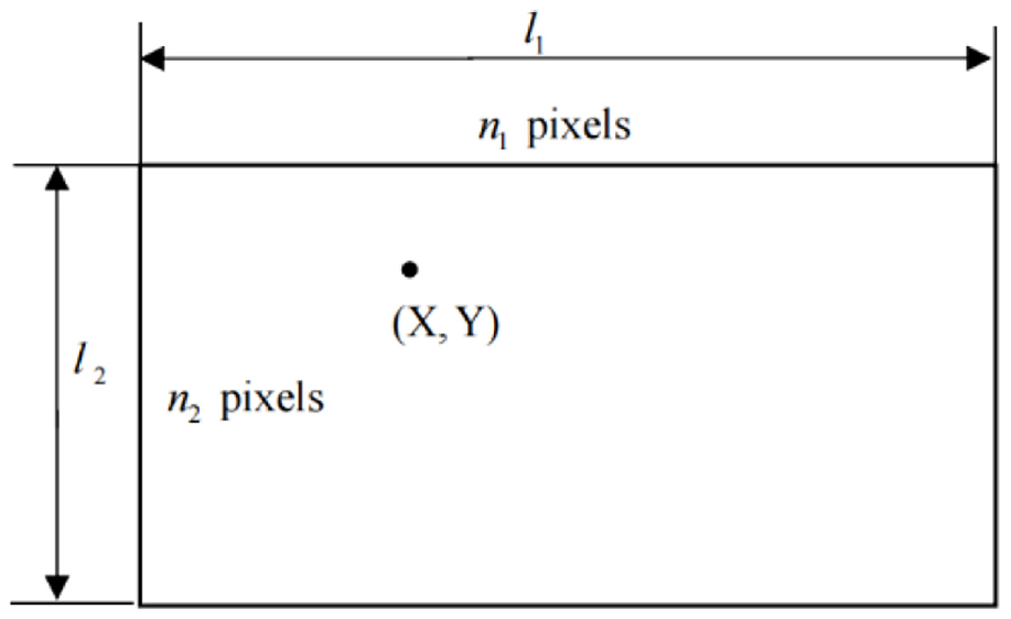
The actual size of the picture is related to the pixel coordinates.
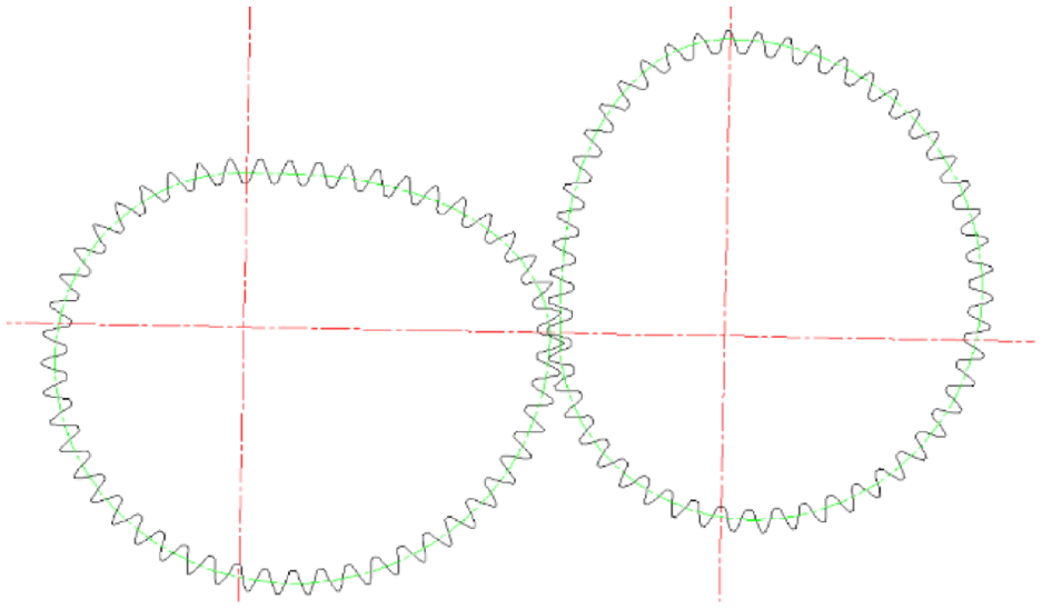
The actual data of tooth profile can be obtained by converting the extracted contour pixels through equation (10), then the actual tooth profile is obtained as shown in Figure 20. The driven wheel can use the same principle get the data points. Finally, the gear pair is obtained, as shown in Figure 21. The green line in the figure is the nodal curve. The driving and driven wheel tooth profile data can be imported into 3D software to directly achieve the 3D modeling of denatured elliptical gear, as shown in Figure 22.

Actual tooth profile of the driving wheel.
Denatured elliptical gear pair.

3D model of the denatured elliptical gear pair.
Precision analysis of eight-neighborhood algorithm
Because of the particularity of non-circular gear, it is impossible to analyze the precision of the extracted tooth profile data directly. The following uses eight-neighborhood algorithm to extract the image edge of the circle, then the precision analysis is carried out.
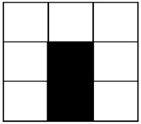
As shown in Figure 23(a), a square with sides of 30 mm, and a circle with a radius of 10 mm is removed from the center, Figure 23(b) shows the inner boundary profile of a circle obtained by the method in this paper. Table 1 shows that by changing the number of pixels per unit length of the output image, then calculates the distance between the extracted data points and the center of the circle.

Square and extracted inner profile: (a) Circle and square and (b) extracted inner profile.
Image changes and accuracy analysis when changing different pixels.
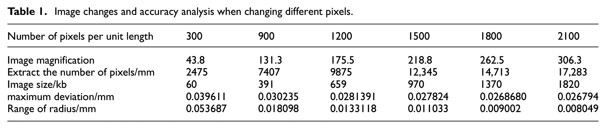
According to Table 1, the more pixels are set per unit length, the more pixels points will be extracted, the fluctuation range of data points will be smaller, and the data points obtained are closer to the actual value. But the more pixels are set, the bigger image is export, and it will increase the time of image reading and profile extraction. So, it is not that the more pixels are set, the better, on the condition that it can reach the corresponding modeling or manufacturing precision requirements.
In this paper, the eight-neighborhood algorithm and the method of Wang
30
are applied for comparative analysis. The elliptical gear equation in Wang
30
is

Contrast diagram of tooth profile extraction. (a) Method comparison analysis diagram and (b) partial enlarged diagram.
Through comparative analyses, the eight-neighborhood algorithm is basically consistent with the tooth profile data extracted in Wang. 30 However, the tooth profile data extracted by the eight-neighborhood algorithm is smoother and has no obvious curvature, while the tooth profile data extracted by Wang 30 is missing at the top and root of the teeth. In addition, the latter takes a long time, more than 20 h. Therefore, it can be concluded that the Eight-neighborhood algorithm is correct in extracting the tooth profile with a high accuracy
Trial production of denatured elliptical gear
To prove the correctness and applicability of the tooth profile extraction algorithm, the trial production of non-circular gear was carried out. Import the extracted tooth profile data into the wire cutting machine, and the machining accuracy is less than or equal to 0.05 mm; roughness 1.0 ≤ Ra ≤ 1.6. Non-circular gear machining by CNC wire cutting machine; the material is 45# steel; thickness is 10 mm. A pair of denatured elliptical gear pairs were manufactured, as shown in Figure 25. The driving wheel can normally drive the driven wheel, and the rotation is flexible without blocking. It shows that the designed tooth profile, tooth height and tooth root transition curve of non-circular gear are reasonable.

Denatured elliptical gear wire cutting object.
To verify the difference between theoretical tooth profile and manufacturing, the denatured elliptical gear pair is tested. In this paper the three-coordinate measuring machine is not selected due to the large number of teeth of the denatured elliptical gear pair, leading to the high cost of testing for all tooth profiles, and troublesome data processing. The measuring instrument is a YuZhi quadratic element measure machine, and its accuracy is (3 + L/150)

Denatured elliptical gear pair measuring process.
The comparison results between the data obtained by the quadratic element measure machine and the extracted tooth profile data obtained by the eight-neighborhood algorithm are shown in Figure 27. The black line is the measured data, while the red one is the theoretical tooth profile. This paper only presents part of the tooth profile, and the overall data are basically the same. Figure 27(a) and (b) represent the tooth profiles of the driving and driven wheel, respectively. By comparing the error distribution results of the Guozheng et al., 31 it is found that the error of this paper is in a reasonable distribution range.

Tooth profile coordinate point detection image: (a) the driving wheel and (b) driven wheel.
Conclusion
The denatured elliptical gear pair is studied in this paper, and the complete envelope image is obtained by piecewise gear shaping and merging. Then eight-neighborhood algorithm is used to extract the tooth profile data of denatured elliptical gear, compared with the existing literature, this paper has the following advantages.
(1) The arc length of the pitch curve of denatured elliptical gear is calculated by the Trapezoidal numerical integration method, compared with the existing methods, it has simple process, low computation complexity, and accurate results.
(2) The overlapping problem of envelope tooth shape that existed at the splice of denatured elliptical gear was solved. It provides a new idea for the design of denatured elliptical gear.
(3) Eight-neighborhood algorithm is proposed to extract tooth profile data of denatured elliptical gear, this method does not need to use the complex gear meshing equation. This method has many advantages, for example, simple program, less time, high accuracy, and no complicated numerical calculation. Tooth profile data can be directly used for 3D modeling or wire cutting machining.
(4) This method takes less time to design denatured elliptical gear and has strong logic.
(5) This method has good stability and can be used to develop the underlying principle of the parametric software for denatured elliptical gear.
(6) Eight-neighborhood algorithm extracts the tooth profile of non-circular gear. It applies to both gear shaping envelope and gear hobbing envelope, it is more applicable than the existing methods.
Footnotes
Handling Editor: Chenhui Liang
Author contributions
Weizhen Song and Yong He was in charge of the whole trial; Weizhen Song wrote the manuscript; Yanghua Zhou assisted with design and experiment analyses. All authors read and approved the final manuscript.
Declaration of conflicting interests
The author(s) declared no potential conflicts of interest with respect to the research, authorship, and/or publication of this article.
Funding
The author(s) received no financial support for the research, authorship, and/or publication of this article.
Availability of data and materials
All data generated or analyzed during this study are included in this published article.