
Abstract
In the operation process of metro, abnormal vibration occurs at the axlebox, and causing structure damage on some components, so the dynamic test was carried out. The result shows that the abnormal vertical vibration about 80–120 Hz is the direct cause in the vehicle operation, and it relates to the type of track bed. According to the track and vehicle, two finite element vertical models of vehicle-track coupling system were established. It determines that the first order vertical bending mode of rail in the coupling system is the excitation source of the abnormal vibration through frequency analysis. And this mode is mainly related to the vertical stiffness of fastener and rubber cushion under short sleeper, which will increase with these stiffness values. Finally, through actual stiffness measurement, it sees that the fastener vertical stiffness values in ordinary track section are mostly reduced to the frequency range corresponding to the first vertical bending mode of rail in the coupling system, which is the cause of abnormal vibration. Therefore, by adjusting the fastener vertical stiffness or adopting the track type to be a damping track bed, the impact of vibration near 80–120 Hz can be reduced, so as to avoid the structural failure of vehicle components and ensure the operation safety of metro vehicles.
Keywords
Introduction
The metro traffic has gradually become an important part of urban public transportation. From the perspective of urban development planning, metro traffic is in the peak period of construction and operation. However, in the process of metro operation, the failure of structures on vehicles is common problem, such as axlebox cover, bolts, coil spring, ground wire terminal and other components often appear cracks and fracture, then resulting in failure.1,2 This will cause huge economic losses and security risks. Improving the factors of the structure can increase its performance, but it is more important to clarify the primary cause of the failure, this is the root of the solution.
According to statistics, most structural failures of metro vehicles are caused by stress vibration, which is usually caused by abnormal vibration during the operation of the vehicles. Therefore, finding the source of the abnormal vibration is the fundamental to solve the fault. At present, in addition to focused on material properties and processing technology, the research on structural failure of vehicle has also turn to structural stress and abnormal vibration. Morsy et al. 3 perform chemical analysis and tensile testes on the faulty coupling, which showed that the material was in compliance to standard, but the presence of pores in the fracture planes indicated that fatigue began with pore defects. Wang et al. 4 obtained dynamic stress and working state data of the vehicle when it was in operation through filed tests, damage analysis was performed for rail corrugation, wheel polygon, rail joint, velocity, and passenger capacity. And the result indicate that rail corrugation accompanied with wheel polygon is the main reason for the damage of bogie frame. In view of the frequent failures of the coil spring on metro vehicles, Zhou et al. determine the bending mode of the coil spring through hummer test and simulation of a finite element model. The influence of P2 force and corrugation on the spring vibration was simulated. And the results suggest that the abnormal vibration was manly caused by the resonance of spring arising from the P2 force of the slab track with fixed sleepers, and the rail corrugations will aggravate the vibration. 5 Such a conclusion can also be obtained in the paper of Sun et al. 6 It is also based on the principle of mechanical resonance, Wu et al. 7 investigate the effect of wheel polygonization on axlebox vibration and bolt self-loosening of high speed train.
In this paper, based on the phenomenon that the abnormal vibration on the metro vehicle and even leads structural, the structure failure of vibration is studied. The purpose is to explore the primary cause of the failure from the perspective of model vibration. The characteristics of abnormal vibration related to the failure are studied through field dynamic tests. And finite element models are established for verification, which is used for studying the influence of parameters on the model vibration of the vehicle-track coupling system.
Structural failure on metro vehicle
Structural failure
With the rapid development of metro traffic, the number of metro vehicles has been greatly increased, and the phenomenon of structural faults has gradually increased, most of them exist on bogie, and these faults are usually fatigue failure caused by abnormal vibration. It is found that cracks exist in some components of bogie during the maintenance, some even broken. Therefore, it is necessary to explore the causes of structural failure, so the field test and modeling simulation analysis are carried out based on this vehicle. Figure 1 shows the ground wire terminal fracture found on metro vehicle.

Ground wire terminal fracture.
When vehicle structure fails, it is necessary to determine whether there is a quality problem. Through the analysis of the relevant structure on the metro vehicle with structural failure, it is determined to meet the standard. Therefore, further research is needed to determine the influence of other factors on the structure. For this phenomenon of fracture failure, the stress vibration of the structure is mainly analyzed.
Field test analysis
In view of the phenomenon of structural failure on the metro vehicle, the dynamic tracking field test was carried out on the vehicle with this fault. Acceleration sensors are installed on key components of the vehicle to collect vibration signals of each component during the operation, such as carbody, frame, axlebox, ground wire bracket, ground wire terminal, etc. As shown in Figure 2, it is part of monitoring points, so as to determine the real-time vibration characteristics.

Some monitoring points.
Data collection while the metro is running on the entire line, according to the platform, the operation metro line can be divided into seven sections, which are marked from S1 to S7. Figure 3(a) shows the vertical vibration acceleration of axlebox, ground wire terminal, and ground bracket during the operation of the vehicle on the whole line. As it can be seen from the figure, the vibration varies greatly in different sections, and the overall performance is that the acceleration in S1 to S3 is much less than that in S4 to S7. When the vehicle runs at some sections, it produces more intense vibration, which makes the amplitude of vibration acceleration suddenly increased.

Analysis of vertical vibration acceleration on axlebox: (a) time-domain of up-going; (b) STFT of up-going; (c) STFT of down-going; (d) time domain analysis, running speed, and type of track line; and (e) time-frequency analysis.
Many components of bogie are fixed on axlebox, including ground wire line and ground wire bracket, there is no excitation source in themselves, all vibration comes from axlebox. Therefore, the short-time Fourier transform (STFT) of acceleration signal at axlebox is carried out to determine the frequency component of the vibration, including the up-going and down-going processes, and the result is shown in Figure 3(b) and (c). Obviously, during the operation of the vehicle, an abnormal vibration occurs on the axlebox, which is mainly concentrated in the range of 80–120 Hz. In combination with the speed, as shown in Figure 4(a), the vibration does not change with speed, so it can be judged that this abnormal vibration frequency is a natural frequency of vehicle in the process of operation. By comparing the up-going and down-going processes results, it can clearly know that this vibration will appear only when the vehicle is running at some fixed sections, mainly concentrated in section S4 to S7. Therefore, it can be determined that the vibration variation is related to the track.

Dominant frequncy analysis of section S7: (a) ordinary track bed and (b) damping track bed.
According to the actual metro line, there are two types of track bed structures, the ordinary track bed and the elastic support block damping track bed respectively, both of them are ballastless track. Among the whole line, the section S1–S3 adopts damping track bed, and ordinary track bed is adopted in section S4–S6, while both of them are adopted in section S7, in Figure 3(d). Then, the time-frequency analysis results of the section with obvious abnormal vibration were selected for amplification (S6 and S7), as shown in Figure 3(e). The frequency component of the abnormal vibration is not a fixed value, but exists within the range 80–120 Hz. When the vehicle passed through the two different type track bed sections, the vertical vibration acceleration on axlebox changes obviously. Which appears in the sections of ordinary track bed with a large amplitude, but not obvious in the sections of damping track bed. It can be concluded that this abnormal vibration frequency is not only related to the vehicle, but also closely related to the track system, especially the type of track bed. When the vehicle passes through ordinary track bed section, it maybe the coupling frequency which leads to the abnormal vertical vibration under resonance action.
Then, the dominant frequency analysis of the vibration signals was carried out respectively when vehicle passes through ordinary track bed and damping track bed in section S7, shown in Figure 4. When passing through damping track bed, the dominant frequency is about 60 Hz, and existing in the axlebox, bracket and terminal, about 0.1 g. However, except 60 Hz, there is a dominant frequency about 90 Hz with larger amplitude, about 0.18 g in axlebox, and the frequency band nearly ranges from 80 to 120 Hz. Among them, the frequency about 60 Hz is the P2 resonance frequency which generated at a speed about 70 km/h. 8 Therefore, it can be judged that the frequency about 90 Hz is the excitation source that causes the abnormal vertical vibration.
Finite element modeling
According to the above analysis results of the field test data, it is known that the phenomenon about abnormal vibration or even fracture of the ground wire terminal on the axlebox involves many aspects, such as the vehicle and the track. In order to study this problem, the corresponding finite element model is established by the method of vehicle-track coupling. This model is mainly composed of two modules, the vehicle module and the track module, which are established by simulation software HyperMesh and combined with ANSYS for finite element analysis.
Modeling of vehicle
Vehicle is the basis for study of railway system dynamics, in order to increase the computational efficiency of model simulation and reduce the influence of secondary factors, some structures of vehicle need simplify in the simulation model, such as the shock absorber and suspension system are simplified as spring damping units, mass of carbody is simplified as the force applied to the bogies in the simulation model,9,10 and so on. According to the actual vehicle parameters in Table 1, the simplified finite element model of vehicle is established, Figure 5 shows a semi-vehicle with one bogie as the main part. It mainly consists of a bogie frame, two wheelsets, four axleboxes, and other simplified spring damping element and force. The solid structures in model are meshed with element type Solid185, and the simplified spring damping element is represented by element type Combin14.
Main parameters of vehicle.


Finite element model of metro bogie.
Modeling of track
In the metro line, ordinary track bed is composed of rail, fastener system, short sleeper, track slab, subgrade, as shown in Figure 6(a). Short sleeper is completely fixed on track slab, and slab is direct contact with subgrade. As the mass under the rail is very large, the vibration of track is mainly shown as the vibration of rails. 11 While, a rubber cushion is added between short sleeper and track slab of the elastic support block damping track bed, the structure is shown in Figure 6(b). Before the vibration from rail arrives at slab, due to the elastic of rubber cushion, the vibration energy transferred to slab is reduced, achieving the damping effect. The vibration of this track type is mainly shown as the vibration of rail and sleeper. 12

Different forms of track structure: (a) ordinary track bed and (b) damping track bed.
No matter what kind of track structure, the rail is contact with vehicle system in direct, its vibration affects the wheel-rail matching relationship, and the excitation generated by it is main source of vehicle dynamics. When establishing flexible model of track system, Timoshenko beam model with equivalent continuous elastic supported is used to simulate sleeper discrete support of rail system, and the low order natural vibration of the wheel-rail system can be analyzed with satisfactory results. Due to the limited influence of track response, the length of rail requires to be optimized under the condition of satisfying simulation accuracy and efficiency, so as to obtain the track vibration response which can cover the target characteristic frequency more accurately and efficiently.13,14 The modal analysis and harmonic response analysis were carried out for finite element model of rail and fastener with different lengths, results shown in the Figure 7. Clearly, when the rail length is less than 18 m, the vibration mode and displacement admittance difference caused by length are obvious, while the length is greater than 24 m, there tend to be unified. Therefore, setting the rail length to 24 m can meet requirements well in the simulation model.

Determination of the rail length: (a) modal analysis result and (b) harmonic response analysis result.
According to actual parameters, two types of track finite element model were established. In ordinary track model, track slab and short sleeper are consider as a whole, while the spring damping element is used to connect them to simulate the rubber cushion in damping track model, shown in Figure 8. In which the spring damping element Combin14 is used to simulate the elastic connection of fastener between rail and slab, as well as the supporting between slab and subgrade, the beam188 element was used to simulate rail, track slab, short sleeper are simulated by element Solid185.15,16

Finite element model of different tracks: (a) ordinary track bed and (b) damping track bed.
Modeling of coupling system
Since abnormal vibration is generated when vehicle passes through different type of track sections, the excitation source is inseparable from track system. Therefore, it is necessary to connect vehicle system and track system to form a large system, and establish a finite element model of vehicle-track coupling system for research.17,18
The abnormal vibration is caused by vertical excitation as previous analysis, so vertical structure is mainly considered in the finite element model analysis, basic structures are shown in Figure 9. In vertical coupling model, the vertical stiffness of wheel-rail contacting is linearized, the value range is usually 1225–1524 MN/m in metro vehicle.19,20 Similarly, the finite element models of vehicle-track coupling system in were established by coupling the finite element model of the track system and the vehicle system, in which the wheel-rail contacting relationship is simulated by spring element.
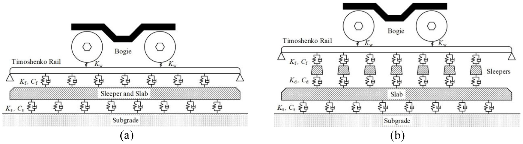
Structure of vehicle-track vertical coupling system: (a) ordinary track bed and (b) damping track bed.
Result analysis
Finite element modal analysis
Based on the basic parameters, natural frequencies of coupling model can be obtained by finite element model calculation. Due to the vibration of track is mainly shown as the vibration of rail and short sleeper, the rail vertical bending in coupling model coupling model is mainly concerned. 21 The first three order vertical bending frequencies of rail vibration are shown in Table 2, and Figure 10 shows the corresponding modes. Among them, 1–3 are the modes with ordinary track, and 4–6 with damping track, the characteristic frequencies differ greatly when the vibration modes of rail are the same in these two systems.
The first three order vertical bending frequency of rail in vehicle-track coupling model.


The first three orders vertical bending modes of the rail in vehicle-track coupling system.
In vertical coupling model, factors that affect natural model are mainly the connection force elements, such as fastener, rubber cushion, slab supporting, and wheel-rail contacting. Therefore, parametric analysis was carried out on the stiffness and damping of these influencing factors to determine their influence on the low order vertical bending mode of rail. From simulation result, stiffness changes of fastener and rubber cushion has a great effect on the modal, while the influence of other parameters is small and can be ignored within the range of consideration.
Influencing of fastener
The rail and sleeper are connected by fastener, which preventing displacement of rails, and providing appropriate elastic damping. When vehicle passes, the load acting on rail is transmitted to sleeper through fastener, fastener determines the transmission efficiency of the wheel load to sleeper. According to the track design, fastener vertical stiffness has a definite value. However, in the operation process, the value of fastener stiffness will change due to the impact of vibration and impact. Through consulting the data, the design standard stiffness of fastener in ordinary track is 50 MN/m, while 40 MN/m in damping track.
For both coupling models, by changing fastener vertical stiffness for simulation analysis, the variation of natural frequencies can be obtained. As shown in Figure 11(a), it is the change of the first three orders vertical bending mode, when stiffness increases from 5 to 100 MN/m. The first three order vertical bending frequencies with ordinary track bed are larger than that with damping track bed under the same value, with the increase of stiffness, the frequency also gradually increases. Figure 11(b) compares the first order frequencies under the two track structures, in which the orange area represents the main range of abnormal vibration frequencies, about 80–120 Hz.

The variation of first three order vertical bending mode of rail with fastener stiffness: (a) first three orders and (b) the first order.
For the ordinary track bed, when the stiffness is in the range of 20–40 MN/m, the first order vertical bending frequency is in the range of 83.03–116.90 Hz, which is consistent with the range of abnormal vibration frequency. While that with damping track bed is in the range of 70.34–78.58 Hz, lower than the abnormal frequency range. In addition, combined with the design value, 50 and 40 MN/m in ordinary track and damping track respectively, and greater than the stiffness range corresponding to the abnormal vibration. Therefore, the abnormal vibration maybe caused by the change of fastener stiffness.
Influence of rubber cushion
In damping track, the rubber cushion can provide elasticity in vertical and horizontal, and slow down the impact on track bed. The force acting on short sleeper is transmitted to track bed through rubber cushion, then a vibration isolation system is formed between them, so the dynamic load is damped, the vibration energy transmitted to track bed is significantly reduced. 22 Since the mass of the short sleeper is fixed, the stiffness and damping of rubber cushion determine the vibration isolation efficiency.
Similarly, modal analysis of the finite element coupling model was carried out after changing the stiffness of rubber cushion. And the natural frequencies of the first three orders vertical bending of rail were obtained. Within the range of variation, the vertical bending modal frequency of rail increases with the rubber cushion stiffness. In Figure 12, it can be judged that when rubber cushion stiffness is greater than 25 MN/m, the first order vertical bending frequency of the rail is greater than 81.54 Hz, combined with the frequency range of abnormal vibration about 80–120 Hz, it will coincide with the area. While, the design value of rubber cushion vertical stiffness is 20 MN/m, which is less than the stiffness corresponding to abnormal vibration generation.

The variation of first three order vertical bending mode of rail with rubber cushion stiffness.
Actual measurement
The metro lines in the process of construction, due to the cost, and according to the actual situation to consider various aspects of different factors, there will be some different track bed structure to be used in the lines, which leads the vehicle coupling with different track bed in the running process, it will produce a lot of different vibrations. The simulation results of two types coupling models were analyzed above, it can be seen that the vertical stiffness value of fastener and rubber cushion have obvious effect on the vertical bending mode of rail. Therefore, it is necessary to measure the actual stiffness, so as to judge whether the abnormal vertical vibration range 80–120 Hz is related to them.
Ten groups of each parameter were randomly selected for measurement, and the results were shown in Figure 13. Generally, the measured stiffness values are less than the design value, in ordinary track section, fastener stiffness ranges from 34.13 to 42.87 MN/m, and most are between 20 to 40 MN/m, which is the range corresponding to abnormal vibration about 80–120 Hz. While, the value ranges from 29.95 to 38.56 MN/m in damping track section, and not coincide with that range. Likewise, the stiffness values of rubber cushion are not reach that range, ranging from 17.12 to 19.13 MN/m.

Actual measured value of stiffness: (a) fastener of ordinary track bed, (b) fastener of damping track bed, and (c) rubber cushion of damping track bed.
Through above analysis, the abnormal vibration in range 80–120 Hz is related to the structure of track and the fastener vertical stiffness. When vehicle passes through ordinary track, the first order vertical bending vibration mode of rail in coupling system is the excitation source due to the changing of fastener stiffness. Since the stiffness of fastener and rubber cushion are not within the range of this excitation, the generation of abnormal vibration is avoided when passing through damping track. Through the stiffness measurement, it can be judged that the abnormal vertical vibration is caused by the reduction of fastener vertical stiffness on ordinary track section, and verify the conclusion of the simulation analysis.
Conclusion
A dynamic performance field test of metro vehicle was carried out about the cause of structural failure due to abnormal vibration. The vertical frequency range 80–120 Hz was studied when the vehicle passing ordinary track bed, which is determined to be the first order vertical bending mode of rail in the vehicle-track coupling system. The track model of ordinary track bed and damping track bed were established, even the coupling model of vehicle system and track system, according to the influence factors of vibration, the finite element simulation analysis is carried out.
Through test data, it can be determined that the vertical vibration range 80 to 120 Hz is the cause of structural failure, and this frequency component of vibration is related to the type of track bed, which only appears in ordinary track bed section. Based on the finite element model simulation of parameter analysis, the vertical vibration is determined by the first order vertical bending mode of rail in the vehicle-track coupling system, and the parameter that has obvious influence on this mode is the vertical stiffness of fastener and rubber cushion. Simultaneously, the stiffness measurement is used for verification, the actual equivalent stiffness is much smaller than design value. In ordinary track bed section, the fastener actual stiffness is mostly reduced to the corresponding range of the abnormal vibration appeared, 20–40 MN/m, while the value avoids the range where the abnormal vibration is located in damping track bed section, which explain why the abnormal vibration is very obvious when the vehicle passes through ordinary track bed section.
Therefore, the vertical vibration range 80–120 Hz can be suppressed by improving the fastener vertical stiffness in ordinary track section to avoid the range corresponding to abnormal vibration, and greatly improving the dynamic performance of vehicle. It is necessary to measure and modify the stiffness of the fastener on the metro line regularly.
Footnotes
Handling Editor: Piotr Koziol
Declaration of conflicting interests
The author(s) disclosed receipt of the following financial support for the research, authorship, and/or publication of this article: The work was supported by National Natural Science Foundation of China (Grant No. 51975485, 52102441).
Funding
The author(s) received no financial support for the research, authorship, and/or publication of this article.