
Abstract
Single port access surgery has brought many advantages and new challenges to the field of minimally invasive surgery. In principle, many of these challenges can be addressed through robotics. Continuum robots in particular have seen a surge in interest in recent years for their miniaturisation potential. However, many applications with these robots have been developed for contactless or low-force tasks. This paper tackles several barriers to high-force tasks with continuum robots such as suturing for Open Spina Bifida repair. A novel continuum robot end-effector is proposed. The end-effector is composed of a distal bending segment and hybrid gripper. First, the novel hybrid gripper specifically designed for continuum robots is introduced. The hybrid gripper can function both as a general surgical gripper and as a needle driver while overall keeping the required input force limited. Second, an optimisation of the continuum structure of the distal bending segment is conducted. The objective of this optimisation is to sustain high tip forces – required by the said high-force contact tasks – while keeping deformations acceptable. Third, a quasi-static model that predicts the coupled effect of bending and gripping is derived. This model predicts the deformation of the continuum structure that is induced by the gripping action itself. It could hence be used to compensate for such deformation and establish a stable grip with the otherwise flexible instruments. Finally, experiments are conducted to validate the new designs and the model. The hybrid gripper has a diameter of
Keywords
Introduction
Single port access (SPA) surgery is an increasingly attractive field of minimally invasive surgery (MIS). SPA promises reduced post-operative pain, improved cosmetic outcomes, shorter hospital stay and faster recovery, 1 but interventions also become more complex to perform. 2 Collisions between instruments, obstruction between multiple clinicians, poor triangulation of the operating site and less intuitive motion 3 complicate adoption of SPA in clinical practice. Robotic assistance has the potential to address above-mentioned issues.
Continuum surgical robots have increasingly appealed to research groups across the globe 4 due to their inherent compliance and ease of miniaturisation. However, apart from some exceptions such as Bajo and Simaan, 5 Smoljkic, 6 and Donat et al. 7 most applications of continuum robots have been developed for contactless or low-force tasks, below 0.1 N (e.g. viewing, lasering, ring and peg manipulation). Indeed, transmitting forces through such compliant robot complicates control and reliably doing such remains a challenge. A popular option to limit the impact of external or actuation forces is to use stiffening sheaths.8–10 These are however complex to manufacture. Establishing large stiffness variations in a miniaturised form factor remains an unsolved problem. Notched bending segments are popular due to their compact size, monolithic composition and hence lower part number and ease of manufacture. By altering the geometry of the notches, the compliance of these continuum robotics can be programmed. But so far – as far as the authors are aware of – no efforts have been done to search for optimal configurations to execute high-force tasks with these notched tubes.
While some interventions do not require active contact such as endoscopy or some catheter navigation tasks, many others do require applying large forces to instruments and targeted tissues. One of these procedures is Open Spina Bifida (OSB) repair. OSB is one of the most common birth defects, affecting

Representation of a multi arm robot similar to the design in Vandebroek et al. 12 over its Open Spina Bifida target. The main contributions of this paper here are marked: ① hybrid gripper, ② bending segment pattern optimisation and ③ bending segment kinematic model.
Developing instruments such as grippers, scissors or needle drivers for such miniature continuum robots is challenging. A pragmatic approach would employ commercial
This paper contribution to develop a new continuum robot end-effector for SPA suturing can be divided in three main contributions. First, Section II presents the novel design of a hybrid between gripper and needle-driver. The instrument has been purposely developed for continuum robots. The hybrid design aims to offer both general tissue and object manipulation capability in addition to secure needle holding. It also operates at low actuation forces. This is important as it helps to minimise the impact of gripping force on the continuum robot’s pose and shape. Second, a structural optimisation for high-force contact tasks of flexible bending segments is presented in Section III. This work envisioned task concerns foetal suturing of OSB closure. The developed flexible bending segments rely on anisotropic behaviour: they can apply large forces with little deformation in their transversal plane (yz) while being compliant in their actuation plane (xz); offering a wide bending angle in the latter. An optimisation is conducted to match this stiffness anisotropy to the task. Third, Section IV introduces a detailed quasi-static model of the bending segment. The model takes the perturbation created by the gripper actuation into account. This model can then be utilised to compensate for the influence of the gripper actuation and keep the segment and gripper pose steady while opening or closing the gripper’s jaws. As far as the authors are aware of, this type of compensation model has not yet been reported in literature. The three contributions are experimentally validated in section V before concluding the paper with a discussion on the model, its potential and insights for future work in section VI.
Hybrid gripper design
Instrumentation of continuum robots is difficult for two main reasons. First, since continuum robots are typically considered when miniaturisation is at stake, the instruments themselves also need to be small in size. Second, any force applied on or by the instrument may affect the robot’s pose. Bearing these challenges in mind, two mechanical advantages have been explored. First, the mechanism has been devised to output a large gripping force for a limited input force. Second, the needle is secured using form-closure rather than force closure. The gripper can function as a needle driver and as general surgical forceps. As far as the authors are aware of, this hybrid design is novel in the field of surgical needle drivers. The gripper design specifications are derived next in Section II.A. Section II.B presents the hybrid design in detail.
Design specifications
The different requirements the hybrid gripper design must respect are listed as follows:
Design and prototyping
To design a compact gripper that can deliver high gripping forces and secure needles in place while minimising its influence on the robot pose, two mechanical advantage principles are implemented. The first principle is force multiplication. Inspiration for the initial design inspiration came from a classic, symmetrical five bar mechanism using a push-pull actuation. To increase the robustness, strength and ease of manufacturing, the design evolved into a three bar mechanism by rendering one-half of the mechanism rigid. In the three bar version, only one jaw is mobile while the other remains fixed. The fixed jaw can serve the additional purpose of a spatula. The designed three bar mechanism allows to multiply the input force thanks to the lever effect taking place.
The second principle is form closure. To securely hold an object, robotic graspers rely either on force or form closure. 19 Force closure requires applying sufficiently large compression forces to produce friction that holds the desired object steady in the graspers. Form closure on the other hand consists in completely constraining the object geometrically. This typically can take place at lower force levels. Based on this principle, a portion offering a three-points contact was designed at the most proximal part of the gripper jaws. The three-points contact forces the needle in a groove and in the right orientation, perpendicular to the gripper’s longitudinal direction. In fact, this principle has been commercialised (e.g. by Olympus Corporation, Tokyo, Japan) for rigid, straight needle drivers where it is referred to as ‘self-alignment’ or ‘self-righting’ needle drivers. 20 The novelty of the design presented here is two-fold: first, utilising this ‘self-alignment’ principle for continuum robots. Second, implementing the ‘self-alignment’ needle-driver together with a traditional gripper. Figure 2(a) shows the resulting design. The following paragraphs verify if this design respects the specifications presented in Section II.A.

(a) Hybrid gripper needle-driver showing the cross-section plane (green), (b) cross-sectional view of the three-points contact for needle locking (0.4 mm OD needle), and (c) same with a 0.8 mm OD needle.

(a) Link diagram of the gripper mechanism and (b) free-body diagram of the mechanism.

Simulated and theoretical
friction (sliding and rotational) is negligible;
the main (action) analysis is done in the gripper’s symmetry (xy)-plane.
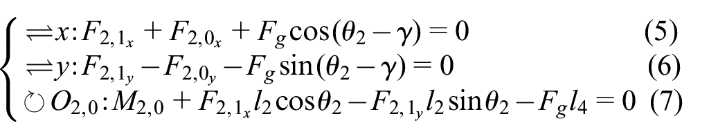
Figure 3(b) shows a free-body diagram that helps derive the relation between the input and output forces. From the diagram one can establish the equilibrium of link 1 along the

Since revolute joints cannot transmit moments,

The equilibrium of link 2 gives:
Following the action-reaction principle, forces on each side of a virtual cut at
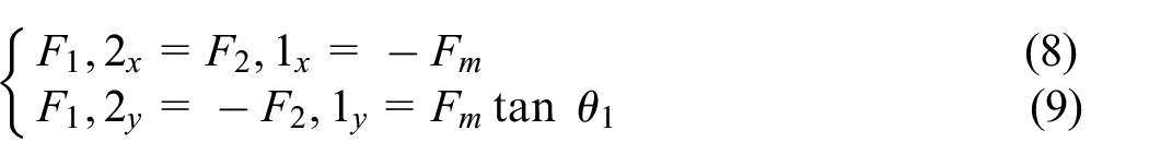
Since
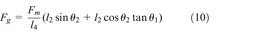
For equal lengths
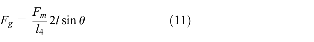
Figure 4 shows the evolution of

Hybrid gripper prototype.
Bending segment structural optimisation
As diameters go down instruments become more flexible. In Vandebroek et al., 12 8 requirements for the OSB repair multi-arm robot were established. They were all met except one: the earlier prototype of the bending segment failed to sustain a transversal force of 1 N. This section describes a structural optimisation conducted to maximise the force that can be delivered at the end of a flexible instrument shaft without buckling or reaching superelasticity. Oliver-Butler et al. 22 conducted an optimisation for single-sided cut-outs but only optimising the cut-out depth to maximise the bending segment stiffness.
This section first describes the geometry and design parameters of the bending segment. Second, requirements for the optimisation are listed. Third, stresses appearing in the bending segment are analysed analytically and through finite element analysis (FEA). Fourth, the optimisation procedure is elaborated. Fifth, the results are discussed and finally, the results are verified against FEA.
Geometry
In order to optimise the flexibility of the bending segment, a cut-out pattern is proposed. Many different patterns have been explored before, as shown in Table 1 of Legrand et al.
23
In Peirs et al.,
24
a
Maximum stress analytically calculated at the four corners beam corners A,B,C,D.


(a) Bending segment geometry and cut-out parameters, (b) second moment of area of the beams, equivalent to the subtraction of two portions of a circle, and (c) second moment of area of a portion of a circle.
In order to calculate the bending stresses and the deformations, the second moments of area are necessary. While cutting the notches, the laser remains perpendicular to the tube surface. This means that the beam section takes on the shape of Figure 6(b). If

Taking the radius of each circular sections as

As there are two beams in parallel (Figure 6(b)), the total second moments of area

Now that the geometry has been described, design requirements for the bending segment must be developed to impose constraints for the optimisation.
Requirements
Following, four requirements

must exceed
Maximum stress identification
From Vandebroek et al.,
12
the transversal load (z direction, Figure 6) that the bending segment undergoes at its tip during a suture through delicate tissue was estimated to be below
(1) Material choice: The chosen material for the bending segment is Nitinol. Its stress-strain behaviour can be approximated as a concatenation of two elastic domains as detailed in Lagoudas.
26
First, the material goes through a linear elastic domain up to a first yield point
By designing the segment such that stresses remain below
(2) Theoretical stress derivation - torsional analogy: There are
It is clear that given the remote action of
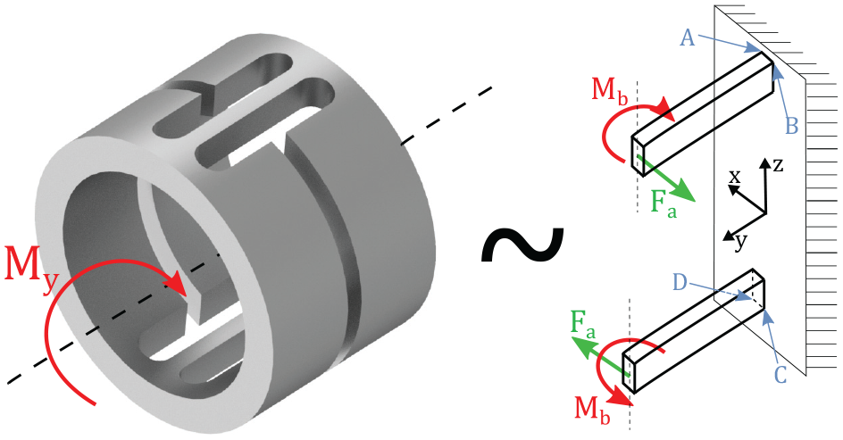
Torsional analogy: the most proximal cut-out under a torsional moment
When observing the small deformation behaviour of the parallel beams during torsion of the segment, one can observe that the two beams actually bend almost exclusively in the

Guided beam analogy to replace
This analogy was validated running an FEA in Inventor (Autodesk, USA). Mesh parameters consisted of an average element size of 4% of the bounding box length, minimum element size of 2% of the average size, a grading factor of
Using this analogy, all stresses can now be calculated. Shear stresses (

With
(3) FEA verification: In order to verify the accuracy of the above analytic derivation, a numerical verification is conducted using the parameters of the previously designed bending segment from Vandebroek et al.
12
:
The FEA is conducted in Inventor (Autodesk, USA) using the same mesh parameters as earlier. The proximal notched section of the tube is clamped at the base.

FEA verification of the stress analysis. The theoretically calculated stress are shown in the black frame for reference.
These high stress values confirm that the previous segment from Vandebroek et al.
12
that was initially utilised for non-contact tasks is not adequate for suturing and hence needs optimisation because
Structural optimisation
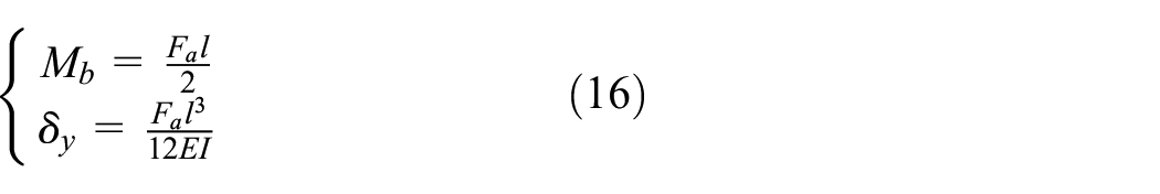
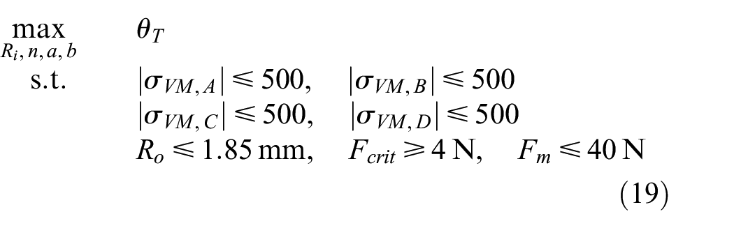
To optimise the structure, the design problem is now formulated as a non-linear constrained optimisation problem. The objective of the optimisation consists in finding the configuration that allows the largest bending angle
Optimisation parameters.

The initial list of optimisation variables includes

Taking into account these relationships reduces the number of independent variables to four:
In order to start the optimisation, an initial guess and limits have to be given to the variables
Results
Two different non-linear constrained optimisation solvers were used in MATLAB (The MathWorks, USA) in order to confront the solvers convergence: APM from http://apmonitor.com/ and fmincon. Both solvers converged towards the same optimal values shown in Table 2.
The first optimisation yielded a bending angle
In order to build a prototype and experimentally validate this optimisation, these initial results were used to select a Nitinol tube available in stock at Euroflex (Germany) with parameters close to Optim. values 1 (as custom production is costly). A few tubes were identified. Their dimensions were used as inputs in the optimisation algorithm. The properties of the tube that provided the highest
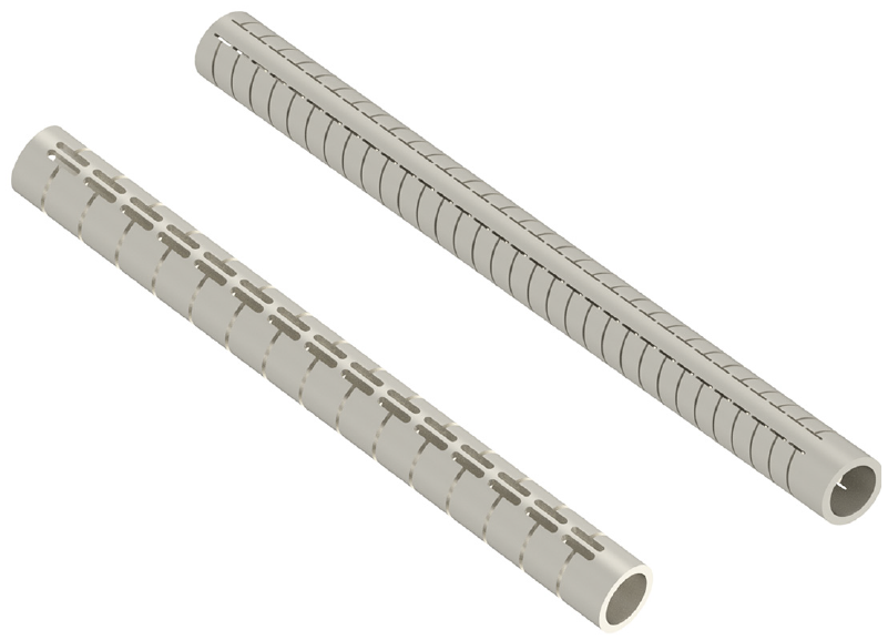
Previous design of Vandebroek et al. 12 (left) versus new optimised design (right).
FEA verification
Running the simulation in Inventor (Autodesk, USA) using

FEA optimisation verification stresses -
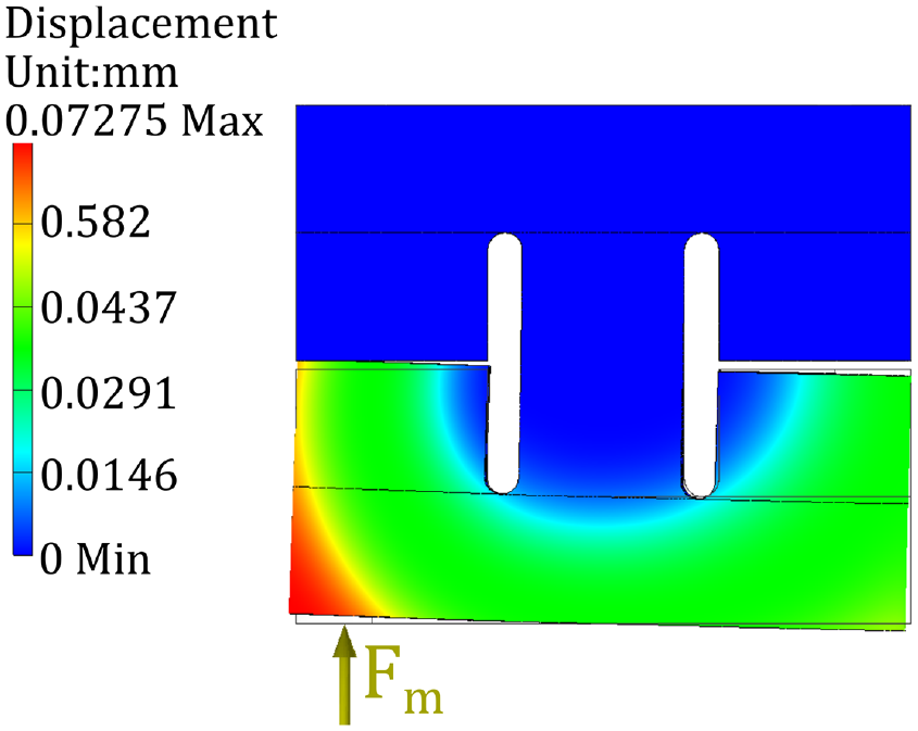
FEA optimisation verification displacement -
Kinematic model and control
The following model takes inspiration from the developments by Legrand et al.
23
and Swaney et al.
27
for unilateral notches. It describes the kinematics of a notched Nitinol tube manufactured by laser-cutting
Modelling approach and hypotheses
First, it is assumed that the segment is initially in a straight configuration and that the input tension

Single cut-out section kinematics. Only half of the bending segment is represented thanks to the YZ plane symmetry.
Next, the segment is considered in a deformed state. The bending cable now generates normal and friction forces on the inner wall of the bending segment. These forces reduce the amplitude of the tip force but also create additional moments. These updated forces and moments yield a different segment shape; which in turn modifies again the different components. To find an equilibrium, this problem is solved iteratively until the change in bending angle between two successive iterations is found negligible. The limit is fixed at
Once this equilibrium is obtained, the gripper at the tip of the bending segment is actuated by pulling the gripper cable. This action creates additional tip, friction and normal forces. The updated problem is again solved iteratively, now taking into accounts forces and moments from both the bending cable and the gripper cable. The computational method is summarised in Algorithm and at the end of this section. The kinematic derivations of this section are based on the following hypotheses
Deformation model of a Nitinol notched backbone – Frictionless model
For space and clarity considerations, the following elaboration is done with respect to Figure 13 which shows only the right half (cut along the
The frictionless model is detailed first as the bending segment is straight in its initial configuration, meaning there are no friction forces. As soon as the segment starts deforming, this changes and this is described in Subsection IV.C.
(1) Deformation of a beam section: The bending cable is attached at the wall of the tube. The cable then runs along the inner wall of the tube, at a distance

This moment is transmitted over the entire bending segment. Classic Euler-Bernoulli beam theory can then be applied (

Additionally, the relationship between bending moment and curvature is

With

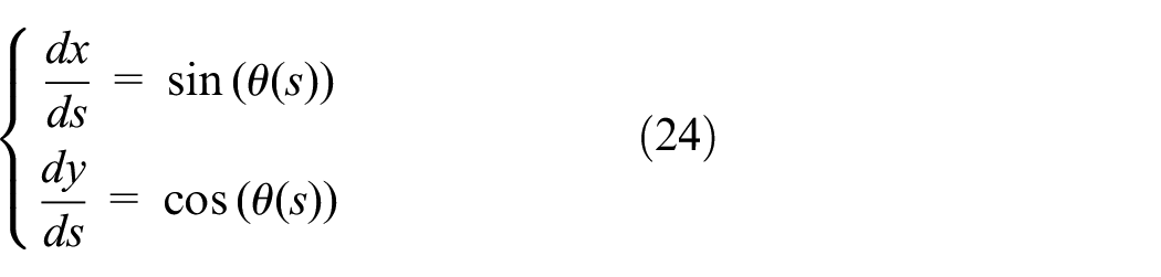
The following geometric relations can then be used to obtain the Cartesian coordinates of any point situated on the neutral axis of the deflected beam at a given arc length
To find the positions

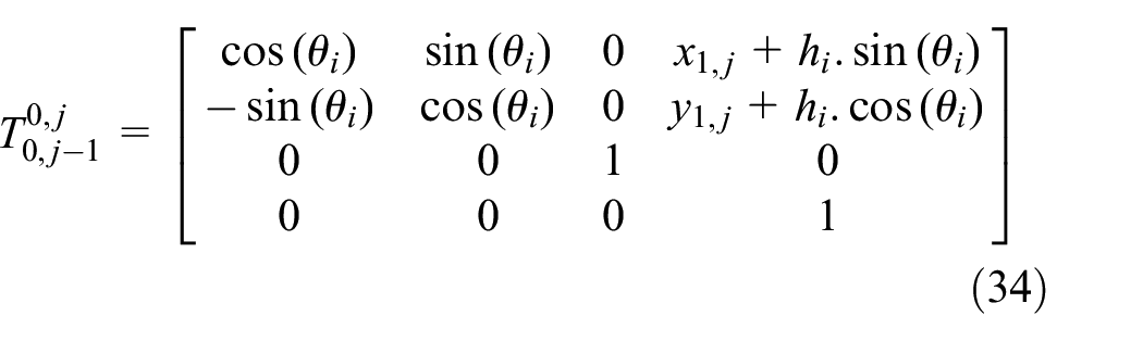
And the transformation matrix that expresses the position and orientation of frame 1 with respect to frame 0 of an arbitrary section j can be found as

With

With

Finally, the middle of the tooth inner wall

(2) Deformations in case of teeth contact: If the moment


Teeth contact when the moment reaches or exceeds
then inserting (30) in (23) gives:

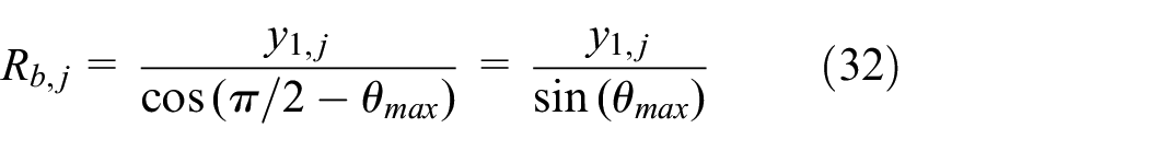
The bending radius can then be found by forming two rectangle triangles with intersecting
or from the arc length formula:

(3) Deformation of the entire backbone: In order to obtain the overall shape of the Nitinol bending segment undergoing a force
The world reference frame corresponds to


Deformed pose of the bending segment.
The origin of frame

The origin of frame

The origin of frame

and the origin of frame

The total bending angle at a specific notch

and the total bending angle of the entire segment is:

Deformation model of each Nitinol notched section - Friction model
(1) Friction between the backbone and the cable - Capstan equation: Now that the segment starts bending,


Capstan based friction model: (a) illustration of the Capstan equation and (b) Capstan approximation applied to the notched backbone.
with

And since

Then, starting from the bottom section

The normal force can then be calculated for each section as:

and the friction force as:

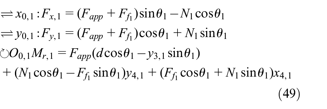
(2) Free-body diagram computation of the bending moment: Now that extra forces come into play, the bending moment will not be constant anymore along the backbone. In order to compute the bending moment and bending angle of each section, a virtual section is made at each origin
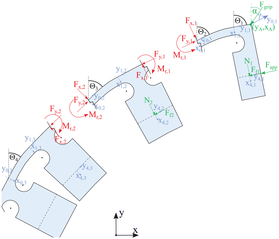
Free-body diagram of the bending and gripping forces.
The distances from section to section will be used as levers for the calculation of reaction moments. Viewed in the local

(a) First section cut: First, let’s calculate the equilibrium at point
Remember that

(b) Second and subsequent section cuts: Moving on to the next segment, equilibrium around
and the new bending angle of section 2 becomes:

The following sections follow the same form, yielding

(c) Deformation of the entire backbone: Equations and transformation matrices (34) to (41) can be used to reconstruct the entire deformed shape of the backbone, using the newly calculated
Gripper contribution
Now that the bending segment has reached the position desired by the surgeon, the surgeon can activate the gripper. Hereto, the gripper cable is put under tension
(1) Gripper force angle identification: When tensioning the gripper cable attached at the anchor point, the cable, shown in green in Figure 18, will naturally take the shortest path. If there is no straight path between the anchor point and the actuator (i.e. the bending segment is sufficiently bent), the cable will establish contact with the inner wall of the tube. This contact will be tangential to the inner wall up to an arc length

Routing of the gripper cable (green), definition of
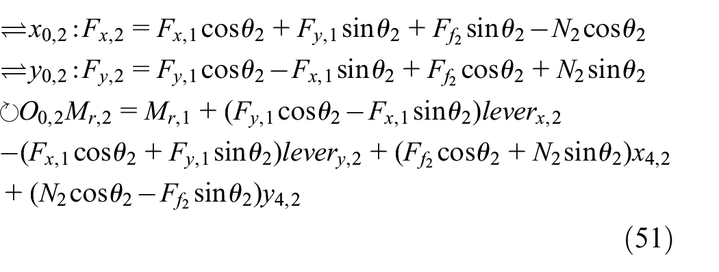
In order to find

From the previous argumentation, the line connecting

The slope can also be written as the slope between the attachment and the tangent contact point:
Now, equating (55) and (56) as

one can solve this numerically to find

The same approach can be followed at the base of the segment where the cable leaves the inner wall to return towards the central axis of the tube (assuming the gripper cable is attached to a centrally positioned actuator in the proximal tube portion).
(2) Friction between gripper cable and backbone: Once the cable path is identified, the beam sections that are in contact with the gripper cable can be identified. Equations (42) to (47) can be used again for these sections with
(3) Free-body diagram analysis: As introduced on Figure 18,

In order to include the influence of the gripper in the new free-body diagram analysis, only the free-body analysis of the first section must be revisited to deal with the inclusion of
(a) First section cut

These forces and moment now allow us to calculate the new bending angle of section 1

(b) Deformation of the entire backbone: The same equations and transformation matrices as in section IV.B can be used to reconstruct the entire deformed shape of the backbone, using the newly calculated
In summary, Algorithm 1 presents the computational method used to find the final bending segment shape in MATLAB (The MathWorks, USA).

Once the initial deformed shape is obtained, Algorithm 2 loops equations taking into account normal and friction forces until finding an equilibrium, with

Once an equilibrium is obtained, Algorithm 2 can be run again to add the influence of the gripper with
Experimental validation
Gripping force validation
To verify the gripping force (Figure 4 and (11)), the experimental setup of Figure 19 is built. A fixed force is applied by a 5 mm McKibben muscle (DMSP-5, Festo, Germany) to the gripper. The muscle is attached to a load cell to measure the force it generates. An Ultra High Molecular Weight Polyethylene (UHMWPE) rope of 0.2 mm diameter from Caperlan (Decathlon, France) is attached perpendicularly to the gripper moving jaw. A load cell at the base of the rope allows measuring the force generated by the gripper. The rope loops 180° around a steel eyelet fixed at the end of this second load cell in order to easily adjust the tension in the rope. The rope can then be pulled until the desired jaw opening angle is reached. The force required to open the jaw can be measured by this second load cell. However, the forces measured by this load cell needs to be corrected by two factors: first, the tension applied on the free end of the rope is higher than the tension applied on the gripper due to the Capstan equation. The first factor is therefore


(a) Experimental validation setup of the gripping force. (b) Zoomed-in view of the gripper during the experiment.
Figure 20 shows the theoretical gripping forces obtained with various input forces and jaw angles. The ‘x’ marks show experimental data points. The experimental values are slightly below theoretical ones due to frictional effects neglected in the mechanism static equations (1) to (11). The experimental results do not cover the whole spectrum of forces due to limitations of the gripper material strength, but sufficiently cover the intended force spectrum.

Theoretical (lines) and experimental (x) gripping force vs jaw angle and input force.
Optimisation validation
In order to confirm the optimisation of the bending segment, a
Tip deflection under 1 N load (a)

Tip deflection vs bending angle with 1 N tip load.
Bending segment model
In order to verify the bending model of Section IV, the segment is mounted onto the setup shown in Figure 23. Two markers are placed at the segment’s proximal and distal extremities in order to track the bending angle, similar to the dynamic characterisation in.
12
The gripper is mounted at the tip of the bending segment. Two cables are connected to a

Experimental validation setup for the bending segment.
Figure 24 is obtained by varying the bending force from

Experimental validation of the bending segment model. Tip bending angle vs input force.
The 10 loading and unloading phases are decently superposed, showing good experiment repeatability. Some hysteresis can be observed as the loading and unloading phases do not take the same path. Both phases take somewhat of an ‘S’-shape typical of hysteresis. The mean between all phases is plotted as a green dotted line. The bending segment model prediction is plotted as a blue dashed line. A decent correlation between the average of loading and unloading phases (green dotted line) and the model (blue dashed line) can be observed. The two lines start and end at the same points but model takes less of an accentuated S-shape and seems more linear. This is probably because the material hysteresis was not taken into account in the model.
Gripper influence model
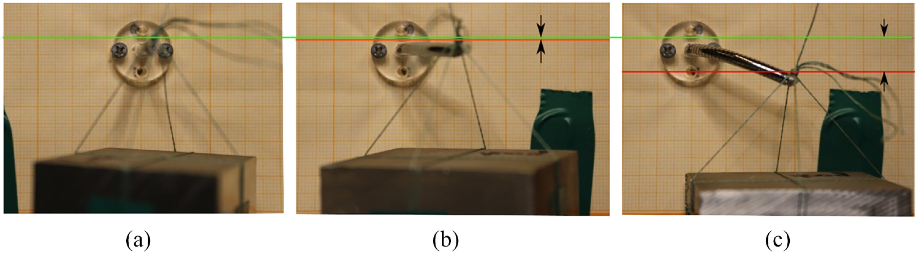
Now that the position model has been validated, the addition of the gripper must also be validated. In order to verify the model, 3 bending forces

Experimental validation of the gripper influence on the bending segment deflection angle.
Figure 25 is presented in the form of a box plot for each of the 10 measurements at each
Gripper influence on the bending angle.

Discussion
The position model validated on Figure 24 reportedly shows a good correlation with the average of the loading and unloading curves. The model is based on the loading phase only but this good correlation means that the model could be used as a decent approximation for both loading and unloading phases. With a mean error of 8.23%, the combined bending and gripping model could be useful to counteract the influence of the gripper: by utilising the model prediction, the gripper influence would be reduced by 25% in the worst case and 96% in the best case; with an average reduction of 68%. In order to run this compensation in real time, a look-up table should be implemented as the model takes about 3 s to calculate the bending segment shape and the gripper influence.
Some important limitations must be considered working with Nitinol. This alloy is very capricious to work with: the slightest heat treatment can affect dramatically its properties, rendering the supplier material characteristics erroneous. In addition, even when one is above the austenite finish temperature, the Young’s modulus remains very dependent of the ambient temperature. The experiments of Section VI.B were run several times throughout the year and various meteorological conditions and the maximum deflection obtained for an identical input force (Figure 24) varied from
Conclusions and future work
This paper first proposed a novel hybrid gripper. The gripper is capable of functioning both as regular surgical forceps and as a needle driver. The design and kinematics were presented in detail. All the design specifications
This paper leaves room for future work. In this work only the loading scenario is modelled. The model could thus be expanded by also accounting for the unloading case. A further expansion could look at the scenario where operation takes place in the superelastic region of the Nitinol (i.e. if the gap
Footnotes
Acknowledgements
This research was funded in part by the Wellcome Trust [WT101957]. For the purpose of open access, the author has applied a CC BY public copyright licence to any Author Accepted Manuscript version arising from this submission. The second part of the funding is a personal Strategic-Basic research Fellowship of the Research Foundation – Flanders (1S96518N). The author gratitude goes to Pr. Van Hooreweder and Ir. Meyers from the MaPS group (KU Leuven) for 3D printing several iterations of gripper prototypes.
Handling Editor: Chenhui Liang
Declaration of conflicting interests
The author(s) declared no potential conflicts of interest with respect to the research, authorship, and/or publication of this article.
Funding
The author(s) disclosed receipt of the following financial support for the research, authorship, and/or publication of this article: Funding from Wellcome Trust [WT101957] and a personal SB research grant from the FWO – Flanders (1S96518N).