
Abstract
The tower crane is a typical soaring and complex frame structure, and buckling is an important factor affecting its safety and carrying capacity. Considering the special characteristics of the boundary conditions for the boom structure, a numerical analysis method based on movable boundaries is proposed in this paper. In order to demonstrate the accuracy of the method, numerical analysis and stress tests are carried out on the tower crane. The results show that the numerical results are basically consistent with the experimental results. A geometric buckling analysis for extremely severe conditions is carried out in order to understand the buckling behaviors. The failure modes and complete load-response curves obtained for the tower crane are comprehensively analyzed. A dual (geometric and material) nonlinear buckling analysis of the tower crane is then investigated. Finally, the influences of the deflection load parameters on the buckling response of the tower crane are explored. It is demonstrated that bifurcation point buckling and limiting point buckling are excited by different deflection load parameters, respectively. The proposed method can accurately predict the buckling of the tower cranes, given the coupling of structure and mechanism, to ensure the safety of giant cranes in actual engineering use.
Introduction
The construction of large scale projects requires large scale cranes, which are also required to satisfy heavy lifting weights and extremely high lifting heights. With the increased demands of aerial operation and the use of high strength steel, frame structures have been designed to be slimmer and lighter. However, slender structures are prone to buckling failures. As shown in Figure 1, failures of tower cranes occur as a result of boom buckling. The working range of a tower crane can deviate due to the load. The luffing mechanism needs to be constantly adjusted to keep the working range unchanged. That is, the tower crane system is a complex system consisting of frame structure and mechanism. Therefore, the buckling study of tower cranes considering mechanism functions has great academic value and engineering significance.

Buckling failure of the tower crane.
The reference formulas provide by the existing design specifications of cranes are suitable for regular structures under conventional loads. 1 According to the traditional stability checking method, the lattice-boom structure is equivalent to the solid web boom, and then the stability checking formula of the structure is given.2,3 The traditional analytical method is applicable to simple structures, such as I-section columns, 4 arch-beam structures, 5 plates 6 and arches, 7 etc. Hu et al. 8 present analytical solutions for the buckling of single beams as well as two- and three-member frames subjected to torques at the supports. Ibrahim 9 presents stability analysis of steel frames composed of linearly tapered columns and partially tapered restraining beams. Wan et al. 10 investigate the influences of Young’s modulus, taper ratio, initial geometric imperfection, and horizontal load on the buckling behavior of tapered piles with different boundary conditions by analytical expression. Li et al. 11 propose an analytical solution for evaluating the critical pressure of pipes under hydrostatic pressure. Zheng et al. 12 provide some new analytic buckling solutions of non-Lévy-type cylindrical panels within the Hamiltonian-system-based symplectic framework. However, the analytical solution is difficult to realize the buckling research of complex frame structures, and the obtained information is also limited.
Numerical simulation is applicable to the buckling analysis of complex steel structures composed of huge numbers of members. Currently, the study of buckling through finite element method has been widely used in thin-walled shells, 13 thick plates, 14 circular tubes, 15 columns16,17 and frame structure. 18 It is very expensive to study the buckling failure test of giant crane, and several experiments are needed for different working conditions. Moreover, the accuracy of numerical model of complex structure can be guaranteed by stress test. Finite element analysis is carried out to investigate the influences of various parameters on local buckling load and ultimate load of I-section stub columns. 19 Hu et al. 20 investigate the nonlinear buckling behavior of steel columns with the finite element method and an artificial neural network. Geometric, material and status nonlinear finite element analyses with implicit and explicit methods were used to study the telescopic boom of an all-terrain crane. 21 Zheng and Wang 22 carried out numerical simulation on concrete-filled steel tubular column-composite beam frame model. Li et al. 23 present a series of numerical simulations of a lattice transmission tower section under torsional (longitudinal) or bending (transverse) loading in both static and dynamic scenarios. Lu et al. 24 proposed computational fluid dynamics modeling and simulation procedures to address the spatio-temporal feature of in-construction buildings and various working conditions of tower cranes.
Linear stability is assumed under the premise that the deformation of the structure before instability is ignored. Although the linear stability study is simple, it is not applicable to soaring steel frame structures with strong nonlinear characteristics. First, the material of the rod has material nonlinearity. Second, space frame structures have variable cross sections along the axis. Thirdly, the luffing mechanism will change the boundary conditions of the boom, that is, the boundary conditions are nonlinear. So the nonlinear buckling analysis can accurately estimate the critical buckling load of boom tower crane. 25 Lee and McClure 26 present the elastoplastic large deformation analysis of a lattice steel tower structure using finite element analysis.
Most of the previously used numerical analysis methods for the study of structural buckling are based on idealized boundary conditions. Small working range is the core working condition. During the actual operation, the luffing mechanism is continuously adjusted to keep the working range unchanged. Under these conditions, the whole structure of the tower crane is in a condition similar to a compression bar and is therefore susceptible to buckling. The structure is prone to buckling failure before strength failure. However, if the coupling between mechanism and structure is not considered, the tower crane will undergo large geometric deformation after gradual loading until strength failure. Therefore, accurate buckling analysis of complex system composed of luffing mechanism and superelevated structure has become a key issue to meet the design requirements of giant cranes.
In this paper, the finite element model of tower crane is established, and then the numerical analysis is carried out by using the method proposed in this paper. The effectiveness of the proposed method is verified by stress tests. An accurate finite element model of tower crane is established, and the effectiveness of the proposed method is verified by stress test experiments. Firstly, geometric nonlinear buckling analysis is carried out to understand the buckling characteristics of the structure according to the time-history response curve. Then, the elastoplastic analysis of the frame structure is carried out. The results show that nonlinear buckling is the main factor affecting ultimate bearing capacity and safety. Finally, the effects of pendulum parameters on the buckling behavior of complex frame structures are analyzed. The results of numerical calculation can provide reference for the formulation of operation specification and safe operation of giant crane.
Numerical analysis method based on movable boundaries
Geometric large deformation of tower crane
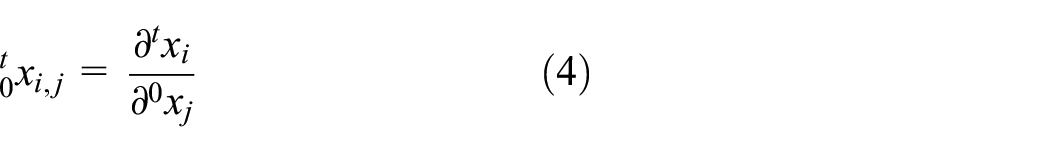
Both the boom and mast have a large slenderness ratio. Therefore, under the action of heavy load, the tower crane will have a large deformation. The boom section that comprises the boom is analyzed. The frame structure continuously changes its configuration under load, as shown in Figure 2. ΔRi is the deviation of the boom section in the direction of vertical projection. P and Q on the structure are selected. 0xi represents the coordinates of the configuration of P at time 0. 0xi+d0xi represents the coordinates of the configuration of Q at time 0. Under the action of external force, the selected points move and deform to a new configuration at time t.txi and txi+dtxi represent the coordinates of P and Q in the configuration at time t respectively. 27

Geometric large deformation of space frame structure.
According to the continuity requirements of deformation, there are

From equation (1) we have


where

then, equations (2) and (3) could be written as


From equations (6) and (7), we have


The change of PQ is expressed as

According to equation (10), the Green-Lagrange strain tensor could be written as

In order to obtain the relationship between strain and displacement, the displacement field is considered,

then we have

Substituting equation (13) into equation (11), we can obtain
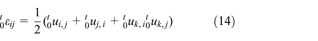
According to equation (14), when large deformation occurs in the frame structure, the quadratic term of displacement derivative in strain expression cannot be ignored. Therefore, the balance equation of frame structures must be established in the deformed state. The calculation accuracy of buckling analysis based on small deformation theory cannot meet the design requirements. Geometric nonlinearity must be considered in buckling analysis.
Movable boundaries
The working range refers to the horizontal distance from the center line of rotation to the center line of the fetching device. For the luffing boom tower crane, the small working range is the core working condition. After lifting heavy load, the load suspension points on the boom top deviate from the initial position. Previous studies mostly ignored the working range change caused by the geometric large deformation in the buckling analysis. 28
In order to keep the working range unchanged, ΔR needs to be eliminated by the luffing mechanism, as shown in Figure 3. During the loading process, the length of the luffing mechanism is constantly adjusted. A nonlinear constraint, the movable boundaries, is added to the buckling analysis of tower crane structures. Therefore, tower crane is no longer a structure, but a complex system of structure and mechanism combination.

Movable boundaries of the tower crane.
Methodology
A finite element model considering the luffing mechanism is established. The load is exerted on the tower crane gradually in load steps. After the calculation of a load step, the deviation value for the working range of the tower crane is extracted. The working range is then made to meet the requirements by controlling the luffing mechanism, which is simulated by a unit with adjustable length. This enables the numerical analysis to account for movable boundaries. For buckling analysis, load until the calculation does not converge, then extract the load-displacement curve and determine the buckling load at the abrupt change.
The flow chart of buckling analysis method as described in Figure 4. ΔR is the deviation between the actual working range and the target working range. Rp is the error precision of working range. Pstep is the load step. Lstep is the adjustment step of the length.

Flow chart of buckling analysis method.
Numerical modeling and experimental verification
Finite element model
The height of tower crane studied in this paper is 185 m, the maximum lifting weight is 135 t. The height of mast is 135 m, and the length of boom is 60.8 m.
The finite element model of tower crane is shown in Figure 5. The space frame structure is simulated using a two-node beam element named beam188. The unit is based on the Timoshenko theory which considers shear and has plasticity, stress stiffening, large deflection and large strain capacity. The deck and stiffening plate are simulated by shell181 unit, a six-node element suitable for nonlinear analysis. The link11 unit is called a regulator unit, whose length can be adjusted during analysis. The luffing mechanism is simulated by link11 unit.

Finite element model of the tower crane.
Stress test experiment
Model test is a common scientific research method to obtain the performance of complex structures. Stress tests under typical working conditions are carried out. Strain measurement is adopted in this paper, which is a typical nondestructive testing method. The stress state of the boom is complex and the chord is the main load-bearing structure. That is, the strain measuring points of the test are all on the chord, as shown in Figure 6(a). The direction of major principal stress is parallel to the chord. As shown in Figure 6(b) and (c), the main instruments include strain gauge and strain-gauge test.
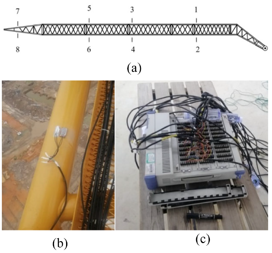
Stress test experiment: (a) test points location, (b) strain gauge, and (c) strain-gauge test.
Since the results measured by strain gauge are axial stress, the axial stress of finite element model is extracted. As shown in Table 1, the error between the simulation results obtained by the proposed method and the experimental results is not more than 4.3%. In contrast, the maximum errors of the results obtained by the traditional method and the linear method are 64.6% and 132.3%, respectively. Thus, the accuracy of the method proposed in this paper is much higher than that of the traditional method.
Comparison of stress results.

This is because the traditional method ignores the movable constraints of the luffing mechanism on the boom in actual working conditions. The experimental results show that the influence of movable constraints on tower crane structure is not negligible. The method proposed in this paper can better simulate the actual working conditions.
Nonlinear buckling analysis
Load combination
According to GB/T 3811-2008, 1 the most adverse load combination is selected. In order to ensure the safety of the crane, the nonlinear buckling failure analysis is carried out for C3 working condition. The load combination (C3) includes dead weight load, wind load and lifting load. The static load is multiplied by the dynamic load coefficient to achieve the equivalent static load because the load will cause the dynamic effect of the crane system. The gravity load factor is selected as 1.02. The rated load is 136 t. The hoisting dynamic load coefficient is selected as 1.2. The wind speed is 15.5 m/s, and the wind load direction is +X. In order to consider the swing of the suspended object, the deflection angle of payload is 2°.
Geometric nonlinear buckling analysis
The lifting load is gradually increased under the worst working condition until the structure collapses. The nonlinear buckling mode of tower crane in multiple perspectives is shown in Figure 7. Tower crane loses its original structure shape and original bearing capacity. In the Z-direction, the whole machine can be equivalent to the cantilever beam structure. The Luffing rod and A-bracket enhance the ability of tower crane to resist deformation in the X-direction. Therefore, the buckling mode is that the tower crane deforms obviously in the Z-direction.

Failure modes of complex frame structure.
Q is the lifting load. UX, UY, UZ are the displacements of P in the X-, Y-, and Z-directions respectively. As shown in Figure 8(a), the working range is adjusted through the luffing mechanism in the loading process until the tower crane buckling occurs. After each load step has been completed, the boom head is displaced in the X-direction under the load. The working range is then adjusted to original state by luffing mechanism. That is, the displacement of the boom head in the X-direction is canceled out. The slight decrease of UX at the end of the curve is due to torsion of the boom.

Load-displacement curves: (a) load-displacement curve in the X-direction, (b) load-displacement curve in the Y-direction, (c) load-displacement curve in the Z-direction, and (d) load-displacement curve.
As shown in Figure 8(d), the slope of load-displacement curve at P changes abruptly when the load reaches about 380.9 t and it indicates that buckling has appeared. That is, the buckling load is 380.9 t, which is about 2.8 times of the rated load. Different from other types of large cranes, 29 the ratio of buckling load to rated load of tower crane is small. The bearing capacity of tower crane is weakened immediately after buckling. According to Figure 8(b) and (c), the deformation in the Z-direction is the most significant. In Figure 8(b), by comparing the load-displacement curves of the boom and mast, it is found that the buckling failure of the boom occurs before the mast, so the boom is a decisive factor determining the stability of the whole machine. Numerical analysis results show that the proposed method can effectively simulate the real load-displacement response and obtain the critical load at the target working range. Significantly, this method can get the critical load by program independent judgment and has a small computational cost.
The material is assumed to be an ideal elastic material, that is, the material will not yield due to excessive stress. The elastic modulus of the material E = 2.1e5 MPa. As shown in Figure 9, in the last substep of calculating convergence, the stress of a chord on the lower side of the boom is the largest. The load-stress response of the chord is shown in Figure 10. When the load reaches the buckling load, the stress increases instantly, that is, the chord has a large strain.

The Von Misses stress nephogram of boom.
The relation between load and stress at each point on the chord.
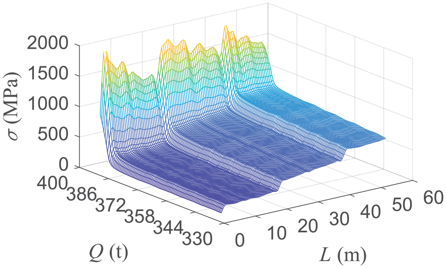
In order to better understand the stress change of each part of the boom, the Figure 10 is shown in slices. As shown in Figure 11(a), stress at all points on the chord suddenly increase at the same time. When the stress reaches about 1000 MPa, the structure loses its bearing capacity quickly with a slight increase in load. Even with an ideal elastic material, the chord will experience large strains when the payload reaches the buckling load. Therefore, if the yield strength of the material is higher than the stress of tower crane buckling, the bearing capacity of the material cannot be fully utilized.

The profile of 3D figure: (a) the relationship between of Q and σ, and (b) the relationship between L and σ.
According to Figure 10, the stress of the chord can be roughly divided into three continuous segments in the length direction. Gradually increase the load until the calculation fails to converge. As shown in Figure 11(b), the three consecutive segments become wrinkle state. Each stress peak in the wrinkle state is much larger than the stresses before buckling.
Dual nonlinear bearing capacity analysis
The elastic-plastic properties of metal materials are an important factor in the study of structural bearing capacity. The traditional analysis method considers the strength and buckling separately, which is not consistent with the actual working conditions. It is necessary to analyze the bearing capacity of the structure considering the material nonlinearity. As shown in Figure 12, the frame structures have obvious plastic deformation after failure.

Failed frame structure.
After large plastic deformation, the structure could not bear the load. In order to ensure the convergence of the calculation, Newmark algorithm is used for transient dynamic analysis of structures with elastic-plastic materials. In order to accurately simulate the buckling behavior of truss structures, the elastic-plastic constitutive model is used for the boom materials. The material properties of chord and web member are shown in Table 2.
Material properties of structure.

The whole process of load-displacement curves can directly represent the whole process of strength and stability of structure. As shown in Figure 13, the slope of the load-displacement curve considering material nonlinearity first approaches 0. Before the structure buckling, the maximum stress of the boom is greater than the yield strength of the material. The plastic deformation of the boom amplifies the imperfection of the structure, so the critical load of the structure decreases. The maximum buckling stress of the boom is close to the yield strength of the material, which can make full use of the bearing capacity of the material.
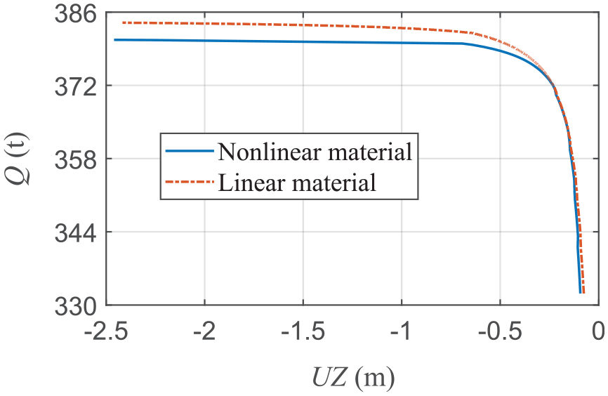
Load-displacement curve in the Z-direction.
Crane structures with irreversible plastic deformation can no longer be used. As shown in Figure 14(a), local strength failure occurred at the fifth boom section. The plastic failure deformation evolution of complex frame structures is shown in Figure 14(b). Initially plastic deformation occurs at a point on the chord bar. The plastic strain region of the chord expands with the increase of Q. The larger plastic deformation leads to “structural softening.” When the bearing capacity of the boom structure is weakened, the stress of the web member near it quickly reaches the yield strength and plastic deformation occurs.

Buckling failure behavior of frame structures: (a) the failure mode of boom and (b) plastic deformation evolution of frame structures.
The instability of the boom in the simulation results is similar to Figure 12. The numerical analysis results coincide with the situation in the accident, which to some extent proves the correctness of the proposed numerical study.
Influence of payload swing
Tower crane is a typical underactuated system, that is, the input control dimension of the system is less than its degree of freedom dimension. The suspended object will oscillate in space under wind load and starting and braking of mechanism. 30 As shown in Figure 15, α is the angle of the payload swing away from the vertical direction, β is the angle of rotation of the load around the vertical line.

The pendulum motion of the payload.
According to the recommendation of national standards, the value range of α is 1°–5°. As can be seen from Figure 16(a), the critical load of structure decreases gradually with the increase of α. Horizontal forces will weaken the bearing capacity of the boom. It can be seen from Figure 16(b) that the relationship between α and Q is slightly nonlinear, and the slope of the curve increases gradually with the increase of α.

The influence of α on structural buckling: (a) the Z displacement curves with load and (b) the relationship between α and critical load.
Considering the axisymmetric structure of the boom, the β between 0° and 90° is selected for numerical analysis. The load-displacement curves corresponding to β = 0, 15, 30, 45, 60, 75, and 90 are shown in Figure 17(a). When |UZ| reaches 20 m, dQ/d|UZ| tends to 0, which can be used as the criterion to judge the instability of the structure. When β is 0, the structure suddenly changes from initial shape to failure state under the action of critical load. Structural buckling under this condition belongs to the bifurcation point buckling. When β is not 0, the deformation increases with the increase of load. When the load reaches the critical load, the tangent value of load-displacement curve gradually approaches 0. Structural buckling under this condition belongs to the limiting point buckling.

The influence of β on structural buckling: (a) the Z displacement curves with load and (b) the buckling characteristics related to β.
As shown in Figure 17(b), β has a great influence on the buckling behaviors. Only when β is near 0, the tower will suddenly undergo large deformation. The maximum difference of critical load in the range of 0°–90° is 25.5 t.
Conclusion
The buckling behavior of tower crane under the extremely severe working conditions is investigated in this paper. The challenging problem of buckling analysis of a tower crane consisting of frame structures and nonlinear mechanism constraint is addressed. According to the special characteristics of the luffing mechanism, a numerical analysis method based on movable boundaries is proposed. The reliability is verified by stress test experiments. Geometric nonlinear buckling analysis and the dual (geometric and material) nonlinear buckling analysis are conducted respectively. Then, critical loads and complete load-response curves are obtained. The effect of α and β on the buckling behavior of tower crane is investigated by means of parametric analysis. The main conclusions of this study are:
The strain data of the key points on the boom are measured by stress test experiments. Compared with the experimental results, the maximum error of the traditional algorithm is 64.6%, while the maximum error of the proposed method is 4.3%. Therefore, the method has a higher accuracy.
Within the constraint of the movable boundary, the tower crane buckles at the working range, which is consistent with the actual operation behavior. The buckling load is 2.8 times the rated load. The buckling mode is that the tower crane deforms greatly in the Z-direction. The stress values of the chord are characterized by a wrinkle state after buckling.
The evolution process of the elastic-plastic deformation of frame structures is obtained by the dual (geometric and material) nonlinear buckling analysis. The local strength failure occurs in the fifth boom section. The results show that the plastic deformation first occurs in the chord and then spreads to the web member.
The parameters of payload have a significant effect on the buckling of tower cranes. The critical load of the structure decreases as α increases and the value of β determines whether bifurcation point buckling or limit point buckling will occur in a truss structure.
The analysis method based on movable boundaries has higher computational efficiency and accuracy. It is suitable for cranes with luffing boom and has practical implications for the safe design of giant cranes.
Footnotes
Handling Editor: Chenhui Liang
Declaration of conflicting interests
The author(s) declared no potential conflicts of interest with respect to the research, authorship, and/or publication of this article.
Funding
The author(s) disclosed receipt of the following financial support for the research, authorship, and/or publication of this article: This work was supported by the Shanxi provincial Key Research and Development Project, China [201903D121067] and the Fund for Shanxi “1331 Project” Key Subjects Construction (1331KSC).