
Abstract
Composite materials have been widely used in civil aviation aircraft, but a large area of ablation damage occurs after lightning strikes, which threatens the operation safety of civil aviation aircraft. The composite material is fixed by multiple fasteners. The different installation positions of fasteners have a great influence on the result of lightning damage of composite. Based on these, a lightning ablation damage model of laminates with multiple fasteners is established, and the accuracy of the model is verified by comparing with the results in the references. In addition, the effect of different installation methods of multiple fasteners on the lightning ablation damage of laminates is studied. The results show that the number of fasteners is not the decisive factor among the factors that affect the ablation damage of laminates with multiple fasteners, and the installation layout of fasteners has an important impact on the damage results. When the fiber direction and aspect ratio of the laminate are the same, the maximum ablation damage area of terrible fasteners layout is 1.27 times the minimum ablation damage area of best fasteners layout under the action of lightning peak current of 200 kA.
Keywords
Introduction
Lightning is a common natural phenomenon with high frequency and can release a large amount of energy in a short time. It poses a great threat to the operation safety of civil aircraft and has led to a number of particularly serious safety accidents of civil aircraft.1,2 According to statistics, an aircraft will have a lightning accident every 1000–10,000 flight hours, and in rainy and lightning areas, civil aviation aircraft will have an average lightning accident every year.3,4
Because carbon fiber reinforced composite material (CFRP) has higher specific strength, specific stiffness, corrosion resistance and other excellent properties than aluminum alloy materials commonly used in aircraft, it has been widely used in civil aviation aircraft. 5 CFRP used in Boeing-787 accounts for 50% of the whole machine materials, and CFRP used in Airbus-350 accounts for 52% of the whole machine materials. In the future, the application proportion of CFRP in civil aircraft may continue to increase.6,7 However, compared with aluminum alloy materials, CFRP has extremely low electrical conductivity and thermal conductivity, and will cause greater damage when struck by lightning. For this reason, the analysis of the impact of lightning on the operation safety of modern civil aircraft is particularly important. 8
Scholars have conducted certain researches on CFRP lightning ablation. Scholars Ogasawara et al. 9 and Fu et al. 10 analyzed the lightning ablation damage characteristics of laminates, and verified the accuracy of the results through experiments; Scholars Ding and Zhou, 11 Xiao et al., 12 Yin et al., 13 Dong et al., 14 and Millen et al. 15 . analyzed the influence factors of lightning ablation damage, and studied the relationship between electrical conductivity, thermal conductivity, heating rate and damage area; Scholars Hirano et al. 16 and Xiao et al. 17 studied the damage of composite laminates under the action of different waveform lightning currents. The results show that the Joule heat generated by different waveform lightning currents has a great impact on the ablation damage of composite laminates. The above-mentioned scholars used the coupled electrical–thermal finite element analysis (FEA) model in the research process, and this method has widely adopted to analyze the thermal ablation damage of CFRP caused by lightning.
The laminate is mainly fixed by fasteners on the aircraft. Hence Scholars Feraboli and Miller 18 and Yin et al.19,20 have studied the lightning ablation damage of laminates with fasteners through experiments and the established FEA model. The results show that the lightning ablation damage of laminates with fasteners is different from that of laminates. Its damage depth is larger, which is more likely to lead to lightning breakdown, and has a more serious impact on the damage of civil aircraft cables and structures. At present, scholars have less research on Lightning ablation damage of laminated plates with multiple fasteners, while most of the laminates used by civil aircraft are fixed by multiple fasteners, so it is more meaningful to study lightning ablation damage of laminated plates with multiple fasteners. At present, lightning strikes are mainly attached to fasteners of aircraft structures, and the severity of their damage is more serious than that of laminates without fasteners. Therefore, a few scholars have studied lightning strikes on laminates with a single fastener. However, most composite structures in the process of lightning strike attachment are fixed by multiple fasteners, and few structures are fixed by a single fastener. Hence it is more meaningful to study the lightning strike damage of laminated plates with multiple fasteners.
Based on these, this paper uses coupled electrical–thermal FEA model to analyze the lightning ablation damage area and mechanism of laminates with multiple fasteners, and influence on the ablation damage of laminates is studied from different angles by changing the number and position of fasteners. The research results have certain reference value for lightning damage analysis and lightning protection of aircraft composite materials.
Method and material
Theoretical model
Assuming that the lightning current is a multi-section steady-state DC current, the electric field distribution of the laminates is determined according to Maxwell’s charge conservation equation.

Where: V is the volume of the unit body; S is the surface area of the unit body; n is the external normal direction of S; J is the current density; rc is the internal volume current.
The current conduction follows Ohm’s law. 21

Where: E is the electric field intensity, defined as the negative value of the electric potential gradient
According to the reference, 22 substituting equation (2) into equation (1), by applying the first chain rule and the divergence theorem to simplify the above equation, the following basic equations for electrical analysis can be obtained.

The rate of electrical energy dissipated by the current flowing through the material can be expressed by the following Joule’s law.

The amount of electrical energy converted into heat (Joule heat)

Where: ηv is an energy conversion factor (Joule heat coefficient).
When lightning current flows through the conductor, the energy dissipated by the material resistance will increase the temperature of the laminates, causing it to heat and expand. The basic equation of transient thermal analysis can be derived as follows:

Where:
Since the temperature of laminates after the lightning strike is extremely larger than the surrounding environment, the heat transfer between the surface of the laminates and the surrounding environment is dominated by heat radiation. The third boundary condition of heat transfer is adopted, 23 as shown in equation (7).

Where:
Due to the anisotropy of electrical and thermal conductivity of composite materials, the temperature and heat distribution of material is nonuniform, forming an anisotropic temperature field. Through heat flux q = q(θ) and generated heat r = r(φ) coupling the above basic equations of electric heating, the potentials, currents, Joule heat and temperature of each unit can be obtained by calculating the two equations (3) and (6). Based on the above calculation method, the commercial software ABAQUS can be used to simulate the damage process of laminates under lightning strikes.
Material properties
The selected laminate material is IM600/133 and the fastener is 7075 aluminum alloy. Due to the large temperature gradient of the laminate during the lightning attachment process, the material will undergo a phase change with the temperature change, and the properties will change. When the temperature reaches 250°C, the resin begins to melt, and the laminate begin to suffer ablation damage. When the temperature reaches 600°C, the epoxy resin completely melts and causes delamination damage of laminate. When the temperature reaches 3316°C, the carbon fiber sublimates and the fiber breaks of laminate. 24 When the temperature exceeds 3316°C, the laminate simulated units are broken down, and the lightning current is directly attached to the next layer. The electrical conductivity along the thickness direction is infinite large, the electrical conductivity in the vertical and parallel fiber directions is infinitely small, the thermal conductivity is infinitely small, and the specific heat is infinite large. 24 In the same way, the electrical conductivity, thermal conductivity, specific heat and other properties of aluminum alloy material also changes with temperature, and the ablation temperature is 7974°C. Tables 1 to 3 show the material properties that change with temperature.
Density, specific heat, and thermal conductivity of laminate with temperature change. 24

Conductivity of laminate with temperature change. 24


In the process of lightning stroke, the laminates will form a large temperature gradient with the external environment, the third kind of boundary condition is used for finite element modeling, as shown in equation (7), and the thermal emissivity is set to be 0.9. During the lightning stroke experiment of composite materials in reference, 20 the ambient temperature is set to be 25°C and the side potential is set to be 0 V. In the process of finite element analysis, the grid attribute is three-dimensional electrical thermal coupling unit DC3D8E, and the grid in the central region is encrypted to obtain more accurate results. The lightning stroke channel has a certain radius, and the fastener can accumulate more charge than the laminate, so the diameter of the region where the lightning current is attached to the laminate is set to be the same as that of the fastener. The above setting conditions can be set in the electrothermal coupling module in the ABAQUS software.
Lightning current waveform
The ARP-5412 standard formulated by Society of Automotive Engineers (SAE) proposes four common lightning direct effect current waveforms: component A (high current), component B (intermediate current), component C (continuing current), and component D (restrike current). 27
A double exponential function curve can be used to simulate the lightning current waveform A, waveform B, and waveform D, as shown in equation (8).

Where:
Different lightning strike division regions on civil aviation aircraft correspond to different lightning strike combination current waveforms. In this paper, the lightning current waveform A with the largest transfer energy and most likely to cause ablation damage to the laminate is used for analysis, which can be defined by t1 (front time) and t2 (time to half value). 27
Results and discussion
Verification of lightning damage model of laminates with fasteners
According to the lightning strike test results of the laminate with fasteners in reference, 20 the specification of the laminate is IM600/133 and the size is 304.80 mm × 38.10 mm × 2.88 mm, 16 layers in total, the laying direction is [45/02/−45/03/90]s, the fastener specification is 7075 aluminum alloy, the initial fastener diameter is 6.35 mm, and the side potential is 0 V. Based on the established FEA model for lightning damage of laminates with fasteners, under the action of lightning current with a waveform parameter of 5/27 and peak value of 150 kA, the lightning damage results of the first eight layers of laminates are shown in Figure 1(a) to (h), and the lightning damage results of the first two layers of laminates in Yin et al. 20 are listed as shown in Figure 1(i) and (j).

Peak 150 kA lightning strike current analysis of ablation damage with single fastener laminate: (a) first layer, (b) second layer, (c) third layer, (d) fourth layer, (e) fifth layer, (f) sixth layer, (g) seventh layer, (h) eighth layer, (i) first layer of experimental damage, (j) and second layer of experimental damage.
According to the analysis of damage results, lightning ablation damage occurred in each layer of the laminate with fasteners, and the damage area was along the fiber direction. The shape of the damage area of each layer of the laminate was completely consistent with the experimental results, which proved the accuracy of the lightning ablation damage model of the laminate with fasteners based on FEA model. Comparing the laminates without fasteners to analyze the lightning ablation damage mechanism of the laminates with fasteners, according to a large number of studies by scholars, the lightning ablation damage of the laminates without fasteners is mainly concentrated in the first few layers, and the ablation damage area of the lower layer is smaller than that of the upper layer. The lightning ablation damage of the laminate containing fasteners belongs to penetrating damage, mainly because the fasteners have extremely high conductivity compared with the laminate, which will transmit lightning current to each layer of the laminate. Since the fiber direction conductivity of the laminate is higher than the vertical fiber and thickness direction, according to equation (3), it will lead to more concentrated lightning current in the fiber direction, and according to equations (4) and (5), the energy generated in the fiber direction is higher, and the shape of ablation damage is also mainly along the fiber direction. In addition, according to equation (6), the thermal conductivity between the laminates also has a great impact on the lightning damage area, which will transfer the heat of this layer to the area with lower temperature at the upper and lower layers. As shown in Figure 1(b), the shape of the damage area is consistent with the fiber direction of the first laminate, rather than mainly along 0° fiber direction, which is precisely the result of the downward heat transfer of the first laminate.
The effect of the layout of fasteners
According to the application characteristics of composite materials in civil aircraft structures, the common diameters of fasteners are 4, 6,and 8 mm, and the common spacing of fasteners is between 3d (fastener diameter) and 6d. The selected laminate has a length of 150 mm, a width of 100 mm, a single layer thickness of 0.191 mm and a total of 16 layers, and the fiber direction is [45/0/−45/90]2S. Figure 2 shows the layout of fasteners, and the circle represents the area where the fasteners are located.

The positions of fasteners layout.
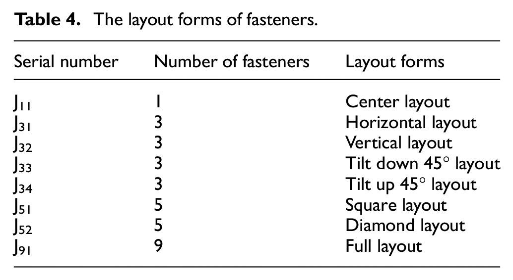
Based on the number of fasteners and different positions of fasteners, eight layout forms are considered in this paper, as shown in Table 4.
The layout forms of fasteners.
After being struck by lightning, each layer of the laminates has different ablation damage. Due to the influence of heat transfer and electrical conductivity, the first layer is a representative layer that reflects the ablation damage characteristics of the laminate. In order to compare the effects of different fasteners layouts on ablation damage, the diameter of fasteners is set to be 6 mm and the spacing of fasteners is set to be 30 mm. Under the action of lightning current with peak value of 200 kA and waveform parameter of T1/T2 = 5/27, the ablation damage results of the first layer of laminates with different layouts are shown respectively are shown in Figure 3.

Lightning damage results of laminates with different layouts: (a) J11 layout, (b) J31 layout, (c) J32 layout, (d) J33 layout, (e) J34 layout, (f) J51 layout, (g) J52 layout, and (h) J91 layout.
It can be seen from Figure 3 that the current transmitted by other laminates will cause different ablation damage in the area around each fastener, and all along the fiber direction. It shows that the fasteners have a great impact on the ablation damage of the laminate. Fasteners at different positions on the laminate can transmit lightning current and heat, and have a guiding effect on the trend of ablation damage. The main reason is that the fastener has a very high conductivity compared with the laminates, so it will approximately shorten the distance from the lightning attachment area to the side 0 V potential field, resulting in an increase in electric field strength, and more lightning current is transmitted along the fastener direction. As shown in equations (4) and (5), it leads to an increase in the energy generated by the laminate in the direction of the fastener.
Compared with the laminates without fasteners, the ablation damage area not only appears in the first few layers, but also transmits the lightning current to each layer of laminate through the fasteners. The fiber directions of different layers are different. When the lightning current is transmitted to the fasteners, it will be transmitted to other layers along the fasteners. As a result, each layer of the laminates will be ablated along the fiber direction. The lightning current is redistributed through the fasteners and heat is transferred to the outside quickly, which can effectively reduce the damage area near the center of the lightning attachment area of the laminates. However, if the transmitted energy is too large, it can also lead to unpredictable ablation damage around the fasteners.
As shown in Figure 4, the ablation damage areas of the laminate under the action of peak currents of 150 and 200 kA respectively. According to the results, it can be found that no matter how much lightning current peak is applied, the ranking of damage area of laminates with different layout fasteners is the same, in which the ablation damage area of laminates with J52 layout is the smallest and that of laminates with J51 layout is the largest. When the peak current is 150 kA, the maximum ablation damage area is 1.16 times of the minimum ablation damage area. When the peak current is 200 kA, the maximum ablation damage area is 1.27 times of the minimum ablation damage area.

Ablation damage area of laminates under different layouts: (a) 150 kA (b) 200 kA.
The influence of multiple fasteners layout on the ablation damage of laminates was studied from different aspects. Firstly, the effect of the number of fasteners on the ablation damage of laminates is explored. Through comparison, it can be found that compared with the single fastener J11 layout, the ablation damage of other multiple fasteners layout laminates does not change regularly with the change of the number of fasteners. From the perspective of J51 and J52 fasteners layout laminates, they are respectively the laminates with the largest and smallest damage among the eight fasteners layouts, and the number of fasteners in both layouts is 5. The main difference is that the layout form of fasteners is different, which proves that the number of fasteners is not the factor determining the ablation damage area.
Secondly, the influence of the direction of fasteners on the damage of laminates is explored. Comparing the ablation damage results of laminates with different fasteners layouts, especially the damage results of laminates with 3 and 5 fasteners, it can be seen that the more fasteners along the fiber direction of the first layer, the larger the ablation damage area, but not the layout form of fasteners perpendicular to the fiber direction, the smaller the ablation damage area, as shown in the comparison results of ablation damage of J32 and J33 fasteners layout laminates.
Then, the effect of the length width ratio of the laminate on the ablation damage is explored. Because the damage area of the laminate of J32 fasteners layout is smaller than that of J33 fasteners layout and the layout direction of J32 layout’s fasteners is parallel to the width, the J32 and J33 fasteners layout are studied respectively. The length and width of the laminate are set to be 150 mm× 150 mm, and the peak lightning current applied is 200 kA. The ablation damage area of the J32 layout laminate is 13.15 cm2, and the ablation damage area of the J33 layout laminate is 13.62 cm2. The ablation damage results of the two are similar, and the damage area is greater than 150 mm× 100 mm laminates, indicating that the damage area increases as the aspect ratio decreases. In order to verify the damage rules, the layout of J31 and J34 were analyzed under the same length and width. The ablation damage area of J31 layout is 13.77 cm2, and the ablation damage area of J34 layout is 16.58 cm2. Comparing the damage area of J31, J32, J33, J34 layouts when the aspect ratio of the laminate is 1.5 and 1, it is found that when the number of fasteners is the same, the aspect ratio and the fasteners layout are the main factor affecting the size of the damage area. For the J31, J32, J33 layouts which is different from the fiber direction, the fasteners layout has little effect on the ablation damage result, and the aspect ratio has a greater influence. While the ablation damage area of J34 fastener layout with the same fiber direction is larger than that of other fasteners layouts.
To further explore the main reasons for the above changes, the potential distributions of the first layer of the laminates with different aspect ratios of J32 and J33 layouts are listed respectively as shown in Figure 5. It can be seen from the figure that the potential trend is mainly along the fiber direction, and secondly affected by the aspect ratio of the laminate. The larger the aspect ratio of the laminates is, the smaller the length in the width direction is compared with the length direction, which leads to the greater electric field strength in the width direction and the more current transmitted along the width direction. At the same time, the potential is also affected by the fastener layout, but the fastener diameter is small, and the fastener layout is weaker than the influence of the aspect ratio.

Potential distribution of laminates with different layouts: (a) J33 layout, aspect ratio 3:2, (b) J32 layout, aspect ratio 3:2, (c) J33 layout, aspect ratio 1:1, (d) J32 layout, aspect ratio 1:1.
It can be seen that the fiber direction, aspect ratio and the layout of the fasteners of the laminate have a great influence on the ablation damage area. With a certain fiber direction and aspect ratio, a good fasteners layout can effectively reduce the area of ablation damage. When the aspect ratio of the laminate is greater than 1, the electric field strength will tend to the width direction, and part of the lightning current will be conducted in this direction. When the fastener is in this direction, the lightning current will be distributed repeatedly on the fastener. Electricity and heat can quickly diffuse to the outside through the fasteners, resulting in a further reduction in the ablation damage area near the lightning attachment area. When the fastener is not located in the width direction of the laminate, due to the action of the fastener, the electric field strength increases, and a small amount of current will be transmitted along the direction of the fastener, and the heat generated also increases according to equations (4) and (5). However, the current transmission direction is not the fiber direction of the laminate, and resistance is high, so the lightning current is difficult to transmit to the fastener and cannot quickly diffuse to the outside. according to equation (6), a large amount of heat will be generated during the transfer process and the temperature of the laminate will rise rapidly, which will further increase the ablation damage area. Hence it can be explained that when the aspect ratio is 3:2, the ablation damage area of the J32 layout laminate is smaller than that of the J11 layout laminate containing a single fastener, while the ablation damage area of the J33 layout laminate is larger than the J11 layout laminate.
For laminates with three fasteners, the J34 layout’s fastener is located in the fiber direction of the laminate, and more lightning current should pass through it to dissipate heat to the outside, but its ablation damage area is the largest. The reason for this phenomenon is that the fastener and the fiber direction are in the same direction, so the electric field strength increases, and the current tends to transmit along the fiber direction. According to equations (4) and (5), the ablation damage area is further expanded.
In addition, the main reason why J31 layout has a larger ablation damage area than J33 layout laminate is caused by the upward heat transfer of the second layer. Since the fiber layer direction of the second layer is 0°, and the fasteners are also located in the 0° direction, the lightning current will tend to develop in the direction of the fiber, and the heat generated also increases according to equations (4) and (5). According to equation (6), the heat generated will be transferred to the first layer, causing the laminate to appear larger ablation damage. When the aspect ratio of the laminate is 1:1, the influence of the edge on the potential is reduced. The lightning current of the second layer will be more likely to transfer in the direction of the fiber, and transmit electricity and heat to the outside along with the fastener. The heat generated near the center area is reduced, and the heat transferred to the upper plate is also reduced.
Hence when the aspect ratio is 1:1, the ablation damage area of the J31, J32, and J33 layout laminates is approximately the same.
Based on the ablation damage analysis results of laminates containing three fasteners, the principle of ablation damage of laminates containing five fasteners can be further analyzed. Compared with all fasteners layouts, J51 layout has the largest ablation damage area. The main reason is that the direction of the fastener is in the fiber direction and the perpendicular fiber direction. Both directions will increase the ablation damage area of the laminate, so the ablation damage area is the largest. For the J52 layout, when the fastener is in the 0° direction, like J31 fastener layout, the damage area should be increased due to the upward heat transfer of the lower layer. However, when the fasteners exist in the directions of 0° and 90°, the heat generated by the second layer can be affected by the fasteners perpendicular to the fiber direction which can disperse the current, so the heat generated by lightning can be further reduced. Secondly, the fasteners located in the fiber direction will also transfer the heat generated by the second layer to the outside, which will further reduce the heat generated. In addition, the fasteners in the 0° and 90° directions can help the first layer transfer current and heat to the outside. Hence the ablation damage area of J52 layout is the smallest according to equation (6).
When the laminate is struck by lightning, different fasteners layouts have different effects on the delamination damage of the laminate. According to previous studies by scholars, when the temperature exceeds 600°C, delamination damage occurs in the laminate. Through the research, it is found that the J34 layout has almost no delamination damage, while the delamination damage area of the other layouts laminates is almost the same, and the damage area is about 1.96 cm2. As shown in Figure 6, the delamination damage results of J51 and J34 fasteners layout laminates are listed respectively.

Delamination damage area: (a) J51 layout (b) J34 layout.
Delamination damage to the laminates around the fasteners can easily cause the fasteners to fall off, posing a certain threat to the operational safety of civil aviation aircraft. Although the J34 layout laminate has a larger ablation damage area, the fasteners in the fiber direction can effectively promote the transmission of lightning current to the boundary, so the delamination damage area around the fasteners is small. For laminates with other layouts, because the fasteners are located in different directions from the fiber, part of the current will develop in a different direction from the fiber under the influence of the aspect ratio of the laminate and the layout of the fasteners. Due to the high resistance of the laminate, the current generates more heat near the center area, resulting in delamination damage.
Conclusion
This paper establishes the electrical–thermal FEA model for laminates with multiple fasteners, and explores the influence of different fasteners layouts on the ablation damage of laminates. The results show that the number of fasteners has little effect on the ablation damage of laminates, and the fasteners layouts have a greater impact on the results of ablation damage. Among them, the J51 layout has the largest ablation damage area, and the J52 layout has the smallest ablation damage area. When the peak current is 150 kA, the maximum ablation damage area is 1.16 times the minimum ablation damage area; when the peak current is 200 kA, the maximum ablation damage area is 1.27 times the minimum ablation damage area.
The results show that the ablation damage of the laminate is mainly related to the fiber direction, the aspect ratio and the location of the fasteners layout of the laminate. When the fastener is located in the fiber direction of the laminate, it will cause the ablation damage area to increase and the delamination damage area to decrease. When the fastener is located in the width direction of the laminate, the ablation damage area decreases, but delamination damage will occur. When the fastener is in the direction perpendicular to the fiber direction of the laminate and not in the width direction of the laminate, it will promote the current to propagate in the opposite direction of the fiber. At this time, the resistance is large, resulting in less lightning current reaching the fastener, greater heat generation, and increased ablation damage area.
When the fiber direction and the number of fasteners are fixed, the fasteners layout different from the fiber direction has little effect on the ablation damage, and the aspect ratio is the main factor affecting the size of the damage area; The fasteners layout in the same direction as the fiber has a great influence on the ablation damage, and its damage area will exceed other fasteners layout.
In the analysis process of this paper, the influence of the laying direction of different laminates on the lightning ablation damage is not analyzed in detail. In addition, because the lightning damage of composite materials involves the comprehensive action of multiple physical fields such as electricity, heat, and magnetism, the analysis process is more complex, so this paper only analyzes the impact of fastener layout on the results of ablation damage. If the research results considering the effects of electromagnetic force, thermal expansion force, etc. on mechanical damage are added, it is more meaningful for the safety of civil aircraft operation. Hence it is one of the research directions in the future to increase the consideration of the laying direction of laminates and consider the impact of more analysis fields on the lightning damage of laminates with multiple fasteners.
Footnotes
Handling Editor: Chenhui Liang
Declaration of conflicting interests
The author(s) declared no potential conflicts of interest with respect to the research, authorship, and/or publication of this article.
Funding
The author(s) disclosed receipt of the following financial support for the research, authorship, and/or publication of this article: The work was supported by the Fundamental Research Funds for the Central Universities, CAUC (Study Code: 3122022064), awarded to Mr. Ma Kai.