
Abstract
Owning to the requirements for longer endurance, larger payloads as well as simpler mechanical structure of tactical UAV, the two-element airfoil technology is introduced. Firstly, the aerodynamic characteristics of five common low-speed airfoils are calculated and compared. The airfoil with good aerodynamic performance after segmentation is selected as initial airfoil. Then, the influence of different segmentation types on the aerodynamic characteristics of airfoils is analyzed, and the segmentation type which brings the best aerodynamic benefits is selected. The slot parameters are optimized by NSGA-II optimization algorithm under cruising, take-off, and a large angle of attack states to obtain a high-performance self-adaption tactical UAV airfoil. Finally, the new airfoil is applied to Sparrow-hawk tactical UAV, the CL1.5/CD of acceleration state increases 15.5%, the CL of large angle of attack increases 20.4% and the CL1.5/CD of cruising state after enlarge the aspect ratio increase12.3%.
Introduction
UAV is one of hot-spots in the development of aviation industry in 21st century. Due to its benefits of low cost, convenient maintenance as well as flexible take-off and landing, it is widely used in many fields, such as agricultural operation, environmental monitoring, disaster relief and so on. In military field, UAV is playing a leading role in recent local wars hence gain much attentions. The U.S. military plans to reduce the number of manned fighters in air force by 40% and increase the number of UAVs by four times in the next decade. 1 UAVs can be classified by different standards, and the most common standard is the maximum take-off weight (MTW). In UAV application strategy of NATO in 2009, UAVs are divided into three levels by maximum takeoff weight, in which the second level is 150–600 kg also called tactical UAV, the first level is less than 150 kg and the third level is more than 600 kg. 2 The second level accounts for about 30% of the total UAVs equipped by NATO. Shadow, Hermes-450, Sperwer and TB-2 all belong to typical tactical UAVs. They could carry 50–150 kg payloads, including reconnaissance, strike, communication and so on. At the same time, they need simple support facilities, low requirements for take-off and landing also could fly at low altitude to avoid detection.
It is also noted that the application of tactical UAV gradually becomes more diversified which shifted from investigation task to the integration of observation and strike. The weight of a Javelin anti-tank missile is about 15 kg, a tactical UAV can carry two or more of them as well as its guidance system for a long time to perform attack tasks which is much economical and practical. For example, the U.S. marine corps planned to equip RQ-7 shadow UAV with Long-nail missiles. The expanding application also set higher standards for the capacity of tactical UAV. U.S. air force put forward the development direction of tactical UAV: longer range, longer flight time, greater payloader, shorter takeoff and landing length. 3 To achieve these goals, it is necessary to improve the aerodynamic efficiency considering the aircraft power system is unchanged. Tactical UAVs mostly adopt the traditional layout, hence, high-performance airfoils become the key technology.
Israel aviation industry found that much payloads of UAV will lead to a great increase in parasite drag and reduce the cruising endurance factor of the aircraft. When the wet area cannot be significantly reduced, the cruising performance of the aircraft must be improved by using higher lift coefficient of the airfoil. 4 At the same time, to ensure aircrafts have proper flight safety margin, the airfoil must have well mild-stall performance. Thus the concept of two-element airfoil with high lift and mild-stall ability is proposed. 5 In fact, it is a kind of high-lift device, which has always been an important research direction in aerodynamic fields. Smith 6 once summarized the fluid mechanism and design principles of high-lift devices, the Rainbow UAV company in China once optimized the trailing flaps and achieved good results. 7 Among high-lift devices, two-element airfoils not only have the advantages of increasing lift and improving mild-stall performance, but also have simple structure as well as light weight compared with others. Besides, it is recognized that two-element airfoils have high efficiency in lift increase than three-element or more. At the same time, it could adjust the flap deflection to different working conditions to achieve self-adaption ability which is very suitable for tactical UAVs.
The typical UAVs which have successfully used two-element airfoils are Heron and Hermes 900 but their weight is more than 1000 kg. Two-element airfoils has not been commonly used in the tactical UAV, mainly because traditional tactical UAV just carry out reconnaissance missions which doesn’t need much payloads so its parasite drag is not very large which is gradually changing now. The airfoils usually adopted by tactical UAVs are low-speed and low-drag airfoils. For example, Shadow-200 UAV adopts NACA-4415 airfoil, Searcher uses Roncz low-drag airfoil. In this paper, the concept of two-element airfoils is introduced to tactical UAV and a two-element airfoil is designed and optimized for tactical UAV to improve its comprehensive aerodynamic performance.
Study on single-element airfoils and segmentation type of two-element airfoils
Initial airfoils
The first step to design a two-element is selecting an initial single-element airfoil. Tactical UAVs’ airfoils usually have the characteristics of large leading-edge radius, large maximum thickness and proper camber according to the aimed lift coefficient. 8 Some airfoils also need to have mild-stall performance. Therefore, this kind of airfoils are selected as the potential initial airfoils for the design of two-element airfoils. However, different airfoils have different design concepts, application scopes, and limitations, which lead to great differences in shapes and aerodynamic performance. Here, five high-lift low-speed airfoils are selected from five typical airfoil series: E856, FX63-137, GOE228, M06-13-128, and NLF-1015, as shown in Figure 1. These five airfoils represent different design concepts of Eppler, 9 Wortman, 10 Gottingen University, Liebeck 11 and NACA 12 for high-lift low-speed airfoils.

Segmentation types
The primary researches on the design of segmentation have paid much attentions to the slot parameters and flap deflection angle but little on the segmentation types. NACA had conducted several experiments on different segmentation types and discussed the influence of the slot entry and slot tip on maximum lift coefficient as well as drag coefficient. Those research found that smooth, gently changing slot inlet and downward bending tip could have aerodynamic benefits on the segmented airfoils based on NACA six-digit airfoils. 13 Generally speaking, the type of segmentation can be divided into L-type, S-type, and C-type, the main characteristic parameters of segmentation are gap and overlap (OL) values as shown in Figure 2(a). In this paper, the strategy of designing the segmentation is as follows: Firstly, determine the position of slot entry and slot tip, set the control points, connect the slot entry slot tip and control points with B-spline curve to generate the slot and flap as shown in Figure 2(b), Secondly, descend flap by dy, retreat flap by dx and rotate it around the hinge point (ox, oy) as shown in Figure 2(a). Additionally, in order to control the separation flow of the flap, a proper leading edge is designed which is generally believed useful to maintain the flow attachment under large deflection angle. 14

Segmentation method: (a) slot parameters and (b) control points.
Calculation method
The CFD calculation adopts automatically generated unstructured mesh, add boundary layer grid and enrich the mesh around leading edge and slot as shown in Figure 3(b) and (c). The enriched mech is surrounded by red dashed lines, those areas have complex flow conditions, for example, the airflow acceleration on leading edge leads to suction peak and flow interaction occurs between upper and lower surface around slot. The computational domain radius is 25 times of chord length and its boundary is set as pressure far-field as shown in Figure 3(a).

Calculation mesh: (a) general mesh, (b) general mesh, and (c) boundary layer mesh.
The CFD calculation adopts transition-SST four-equation turbulence model, it contains

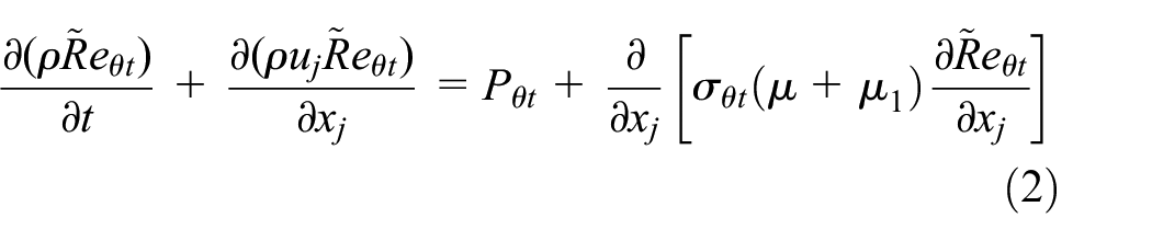
This turbulence model could accurately predict the transition point and calculate the friction drag.
16
Choose the grid shown in Figure 3 for grid sensitivity analysis, set 11,000, 17,000, 28,000, 55,000, 110,000 elements respectively, the calculation results are shown in Figure 4. It could be found that aerodynamic results are stable when the number of elements is greater than 55,000. So take 55,000 elements to carry out calculation, the first layer’s height is

Mesh sensitivity analysis.
Figure 5 is the validation of the 30P30N three-element airfoil in Reynolds number

Numerical validation of 30P30N airfoil with experimental data. 17
Selection of initial airfoil
The slot position is selected according to engineering experiences and slot entry is at 0.65 chord and slot lip is at 0.8 chord. The initial parameters gap = 0.0295 OL = 0.0372, hinge point in (0.8, −0.01), the rotation angle of flap is 5° and the leading edge of the flap remains unchanged. The lift and drag characteristics of the five airfoils mentioned above and their S-type, L-type, and C-type segmentation editions are calculated as shown in the Figure 6.

Lift and drag characteristics of the five airfoils. (a) Cd in different angle of attack and (b) Cl in different angle of attack.
It can be seen that GOE 228 airfoil has higher lift coefficient and lower drag coefficient in four editions. The aerodynamic performance of E 856 is similar to GOE 228, but the overall data is worse than it. FX 63-137 has highest lift performance but rotating moment is worse. Its trailing edge is thin which could not satisfy the structural needs of flap. Hence it is more suitable to be used by gliders. M06-13-128 has a small lift coefficient and easy to stall, but has better rotating moment at small angle of attack, so it is suitable for flying wing or tailless UAV. NLF-1015 can maintain the laminar flow on the airfoil at small angle of attack so the friction drag is smallest, but it tends to stall easily hence easily lose the low-drag characteristics at high angles of attack, so NLF-1015 is more suitable for high-altitude UAV. Finally, based on the calculation and analysis, GOE 228 is selected as initial airfoil in this paper.
Selection of segmentation type
Analyze the aerodynamic data of GOE 228 furtherly to determine its segmentation type. The increasing ratio in lift, drag, rotating moment and endurance factor of three segmentation types are shown in the Figure 7(a) to Figure 7(d) respectively. The positive value indicates increase while negative one indicates decreasing.

Aerodynamic analysis of three segmentation types. (a) 0° angle of attack, (b) 4° angle of attack, (c) 8° angle of attack, and (d) 12° angle of attack.
It can be seen that all the three segmentation types lead to a significant increase in lift among which the S-type is the best. The increase of lift is mainly caused by the circulation effect of flap. Figure 8 could indicate that the S-type segmentation is better to the circulation effect.
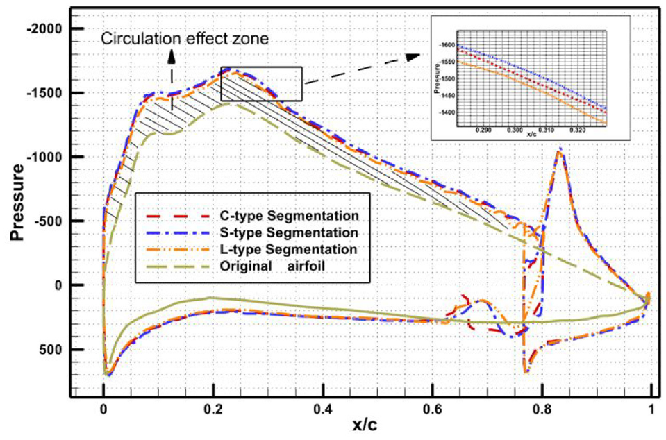
Comparison among three segmentation types.
At large angle of attack which is close to stall, the segmented airfoil can delay the flow separation and alleviate the stall effect. As shown in the Figure 9 at 18°, pressure of airfoil reaches the peak in the beginning owing to the acceleration of airflow in airfoil’s leading edge, then the pressure line declines when airflow starts deceleration, after flow separation the pressure stay unchanged. The green line is the pressure recovery line of the airfoil, which represents the pressure recovery ability of different airfoils. It is generally accepted that for the same curvature distribution upon airfoil, the slope of the pressure recovery line is basically unchanged. For two-element airfoils, the negative pressure peak of flap reduces the reverse pressure gradient, lead to the delay of flow separation on airfoil surface when the slope of pressure recovery line remains unchanged.

Flow separation before and after segmentation.
The streamline around airfoil at the angle of attack 18° is shown in Figure 10 it can be seen that flap can obtain a new boundary layer even flow separation appears on the main body of airfoil, this helps to maintain good aerodynamic performance at large angle of attack.

Streamline around airfoil at high angle of attack.
Also mark the boundary layer thickness according to 99% of the far-field velocity as shown in Figure 11 and compare the boundary layer thickness at the same position between original airfoil and airfoil after segmentation, it can be seen that the thickness of the newly formed boundary layer on flap is thinner than boundary layer on original airfoil after long-time movement, which makes the flow difficult to separate.

Comparison of boundary layers’ thickness.
The raise of lift also leads to the increase of rotating moment. It can be seen from the Figure 7 that there is little difference in increase ratio of rotating moment among different segmentation types. At the same time, it is found that the drag of airfoil generally increases after segmentation, but the drag of S-type increases less. The main reason is that the other two segmentation types cause separated flow in slot as shown in the Figure 12, while S-section produces smooth flow. However, it needs to pay attention to that under some conditions of large angle of attack, the drag may decrease compared with original airfoil due to its good mild-stall performance.

Flow separation in slot. (a) S-type, (b) C-type, and (c) L-type.
In general, segmentation can bring much aerodynamic benefits to airfoils and improve the mild-stall performance. Also, aerodynamic analysis proves that S-type segmentation is better, so it is selected as the segmentation type for further optimization.
Optimization of S-type segmentation and results analysis
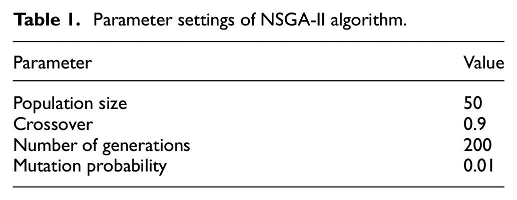
In previous sections, GOE 228 is selected as initial airfoil and the S-type is adopt as the segmentation type. This section will optimize the two-element airfoil based on the preliminary design. Optimization takes NSGA-II algorithm. 18 NSGA-II algorithm is a mature multi-objective optimization algorithm. The advantages of it are good exploration performance and strong moving ability to Pareto front which means approaching Pareto front in less steps, hence could decrease CFD computation expense. So it is often used in aerodynamic optimization.19–21 The parameter settings of NSGA-II algorithm in this paper are shown in Table 1:
Parameter settings of NSGA-II algorithm.
To increase the optimization efficiency, usually 2–4 important aerodynamic parameters are chosen as optimization objectives. In this paper, set cruising and take-off/landing states as the optimization states considering these two flight conditions are critical flight phase for tactical UAVs. According to the engineering experiences, the angle of attack is set as 4° and 10°. At 4° the lift coefficient

The design variables include retreating quantity dx descending quantity dy, hinge point (ox, oy), flap rotating angle
Parameter range and optimization results.

Results before and after optimization.

It can be seen that the aerodynamic characteristics of optimized airfoil has been greatly improved under two setting working conditions. Figure 13 shows the changes of lift coefficient, drag coefficient, lift drag ratio, and endurance factor under different flap deflection angles at different angle of attack after optimization.

Aerodynamic performance after optimization. (a) Cl changes with AOA, (b) Cd changes with AOA, (c) Cl1.5/Cd changes with AOA, and (d) Cl/Cd changes with AOA.
It can be seen that the lift coefficient increases with the increase of deflection angle of flap, and airfoils have the performance of maintaining high lift at a large angle of attack as shown in Figure 13(a). The differences of drag coefficient among different deflection angles increase with the increase of angle of attack as shown in Figure 13(b). The maximum lift to drag ratio firstly increases then decreases with the increase of deflection angle, reaching the maximum value at 4.4° at point 9. The endurance factor increases with the increase of flap’s deflection angle, but the increasing speed decreases. The angle of attack where maximum lift drag ratio and maximum endurance factor appears decrease with the increase of flap deflection angle, and the position where maximum lift to drag ratio is coming earlier.
Based on the above information, take the states which has maximum lift to drag ratio and endurance factor as cruising configuration, so the deflection angle of flap is 4.4°. Under this condition, the lift drag ratio reaches the highest value, the endurance factor reaches a high level, the deflection angle is small so the rotating moment is small, and the cruising lift coefficient reaches 1.6 at point 3 which is a high value. The aircraft could realize the maximum sailing distance where maximum lift drag ratio can be used at an angle of attack 4°–8°, and the maximum endurance factor can be achieved at an angle of attack 1°∼ 4° which could realize the maximum flight time with lower speed.
The flap deflection of takeoff configuration is 12° at angle of attack 8°. The takeoff lift coefficient can be up to 2.3 with the lift to drag ratio 42. It leads to a short takeoff distance and good climbing ability. The landing configuration ensures a large lift coefficient, flap deflection is 18° at the angle of attack 12°. Owning to the airfoil’s mild-stall performance, the maximum lift coefficient is 2.9, so the airfoil also has a large safety margin. Tt can land with a much lower speed combined with a large drag coefficient which is crucial to reduce the landing distance.
Application in tactical UAV
The optimized two-element airfoil is applied to Sparrow-hawk I tactical UAV. This UAV has a bi-tail-boom as well as inverted V-tail. Its span is 3.32 m, average chord length is 0.44 m, total weight is around 200 kg. The propulsion propeller is located at the rear of the fuselage. Tts head is equipped with photoelectric reconnaissance payload and there are two loading points under the wing. The improved Sparrow-hawk II UAV is changed into a segmented wing, the spanwise distribution of optimized airfoil is 1.18 m, the other parts remain unchanged as shown in the Figure 14.

Sparrow-hawk I and Sparrow-hawk II UAV.
Unstructured mesh is adopted for calculation. Boundary layer grid is generated near the wall with the initial grid thickness 0.00015 m and the total number of grids is 20 million as shown in the Figure 15. The computational domain radius is 25 times of plane length and its boundary is set as pressure far-field.

Calculation mesh.
Figure 16 is the calculation results of M6 wing using the same mesh, Re =

Numerical validation of M6 wing. 22 (a) pressure distribution in 44% spanwise length and (b) pressure distribution in 90% spanwise length.
Cruising state
Cruising state is calculated at 4° angle of attack, the results are shown in the Table 4
Comparison between Sparrow-hawk I and Sparrow-hawk II.

It can be found that lift coefficient is substantially increased which could significantly improve the carrying capacity in cruising state, and the increase of drag leads to the decrease of lift drag ratio and the increase of endurance factor. However, considering that in cruising state the two-element airfoil takes endurance factor as optimization target, the optimization goal is basically achieved. Generally speaking, Sparrow-hawk II has advantages over Sparrow-hawk I.
Drag increases
Figure 17 shows the vortex structure near Sparrow-hawk II and Sparrow-hawk I under the same Q criterion at 4° angle of attack, the size and range of vortex structure at different positions could reflect the drag at this position. The vortex structure caused by additional payload can be clearly seen in the figure. The increase of drag could be mainly divided into two parts, one part is the increase of induced drag caused by strengthening the wing tip vortex in area B, which is mainly led by the obvious three-dimensional effect owning to small aspect ratio of the wing, and the other is the increase of drag caused flap in area A.

Vortex of Sparrow-hawk I and Sparrow-hawk II. (a) vortex of Sparrow-hawk I and (b) vortex of Sparrow-hawk II.
Lift increases
Figure 18 shows the pressure distribution in different sections along the wing at 4° angle of attack. The lift rise also could be divided into two parts, one part is the two-dimensional circulation effect, which leads to the increase of the lift of segmented airfoil, as shown in Figure 18(b) and (c). The other part is the three-dimensional circulation effect. Comparing the pressure distribution of the airfoil without segmentation in Figure 16(a), it is found that the lift coefficient of the inner airfoil close to the segmented wing increases, which is mainly affected by the low-pressure area of out segmented wing. It could be seen by the backward movement of blue pressure isoline in Figure 18 which means the decrease of the trailing edge pressure on unsegmented wing.

Spanwise pressure distribution. (a) Pressure distribution at y = 0.3 m, (b) Pressure distribution at y = 0.7 m, and (c) Pressure distribution at y = 1.6 m.
Acceleration state
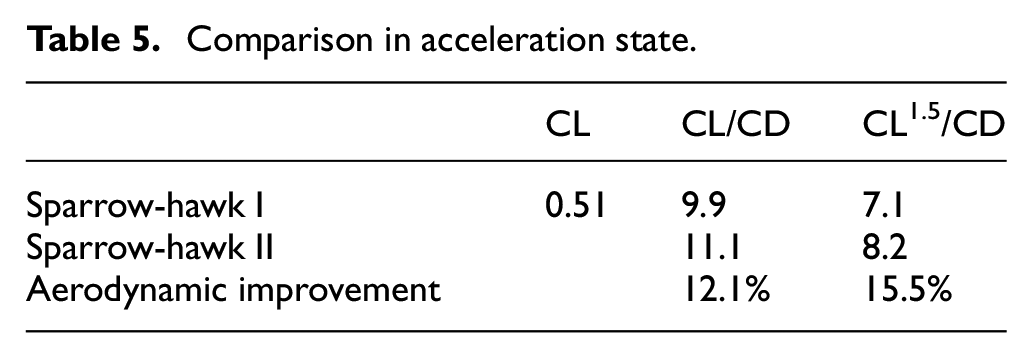
Acceleration state configuration could help aircraft to arrive at mission location quickly. The using lift coefficient is reduced to 0.51. For Sparrow-hawk I, the speed increases by 1.3 times compared with the cruising state, for Sparrow-hawk II, the speed increases by 1.4 times compared with the cruising state. Table 5 shows the aerodynamic data, it can be seen that Sparrow-hawk II has obvious advantages in lift to drag ratio and endurance factor when the speed increases more, This is mainly because Sparrow-hawk I needs to reduce the angle of attack when raising speed, resulting in a larger increase in drag, while Sparrow-hawk II only needs to deflect the flap resulting in a smaller increase in drag. Therefore, Sparrow-hawk II has obvious advantages in acceleration state, which could save more energy and reach the mission area faster than Sparrow-hawk I.
Comparison in acceleration state.
High angles of attack
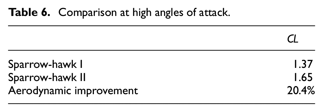
Performance at high angle of attack determines the safety margin of aircraft taking off/landing state as well as the safety of aircraft flying with high lift. Choose Sparrow-hawk I and Sparrow-hawk II UAV with flap deflection of 4° for aerodynamic calculation at 18° angle of attack. In Table 6, we could see the lift coefficient of Sparrow-hawk II is much higher than Sparrow-hawk I.
Comparison at high angles of attack.
At the same time, analyze the separation points at different positions of the wing in same condition as shown in the Figure 19. It can be seen that the separation point in Sparrow-hawk II is obviously backward, which shows that Sparrow-hawk II has the ability to fly at a higher angle of attack and has a larger safety margin. In addition, it is found that the mild-stall performance of two-element wing near the non-segmented wing is less improved, as shown in Figure 16(a), which is mainly induced by the flow separation of the non-segmented wing.
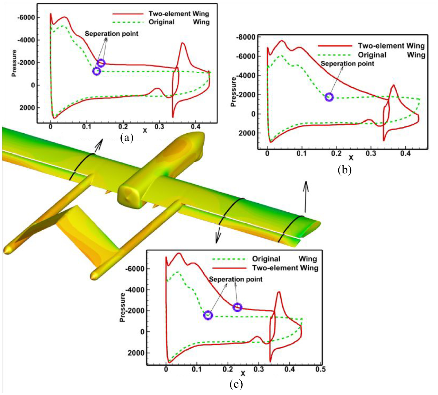
Spanwise distribution of separation points. (a) Pressure distribution at y = 0.6 m, (b) Pressure distribution at y = 1.4 m, and (c) Pressure distribution at y = 1.0 m.
Increase aspect ratio
Sparrow-hawk IV is designed by increasing the aspect ratio of Sparrow-hawk II from 7.5 to 14 as shown in the Figure 20, at the same time, Sparrow-hawk III is generated from Sparrow-hawk I according to the same parameters’ change.
Sparrow-hawk IV.
Their aerodynamic performance at 4° angle of attack is calculated respectively as shown in the Table 7. It can be found that the comprehensive aerodynamic improvement is significantly higher than that in part (1). Because the increase of aspect ratio could decrease three-dimensional effect and cause the reduction of induced drag. This shows that the two-element airfoils have more advantages in high aspect ratio wings.
Aerodynamic performance of Sparrow-hawk III and Sparrow-hawk IV.

Generally speaking, Sparrow-hawk II UAV has small advantages in cruising state and significant advantages in acceleration state and high angle of attack. Therefore, it can be considered that the comprehensive performance of Sparrow-hawk I has been significantly improved, and the effect of improvement is more obvious after increasing the aspect ratio.
Summary
The concept of two-element airfoils is introduced to the design of tactical UAV, the initial airfoil suitable for segmentation is selected, the differences of kinds of segmentation types are compared. NAGA-II algorithm is introduced to optimize the slot parameters and the segmented airfoil with good aerodynamic performance under different working conditions is obtained. Finally, apply the optimized airfoil to Sparrow-hawk I UAV, achieve the overall improvement in aerodynamic performance:
Lift coefficient is increased 20.5% in cruising state with the aerodynamic efficiency unchanged.
CL1.5/CD increases 15.5% in acceleration state and lift coefficient increases 20.4% at high angles of attack.
CL1.5/CD increases 12.3% in cruising state after increase aspect ratio.
This study achieves the overall optimization purpose, shows that the idea of applying two-element airfoils to tactical UAV is correct and potential. But it lacks of related experiments. In the next step, the optimized airfoil should be validated in the flight experiments.
Footnotes
Appendix
Handling Editor: Chenhui Liang
Declaration of conflicting interests
The author(s) declared no potential conflicts of interest with respect to the research, authorship, and/or publication of this article.
Funding
The author(s) received no financial support for the research, authorship, and/or publication of this article.