
Abstract
The coupled vibration in the turbine disk-blade system (TDS) is one of the main bottlenecks that hinder the further development of high-performance engines. To analyze the vibration of the TDS, three types of contact conditions, involving bonded, frictionless, or frictional were used to simulate the contact between the turbine disk and the blades. Three finite element analysis (FEA) models of a typical TDS based on the tenon structure were developed. The experimental system was developed and experimental modal analysis (EMA) was performed. According to the comparison between FEA and EMA results, the most accurate model is the frictional contact FEA model. The average error of the frictional contact FEA model is 1.42%, and the root mean square error is 0.75%. The working modes of the TDS at different speeds were calculated using the frictional contact FEA model. Meanwhile, based on the newly developed FEA model, it is found that the weak links in the TDS are the blades. This work can provide a theoretical basis for the TDS structure optimization and promote the development of high-quality aero-engines.
Introduction
Despite strict standards and practices in the manufacture of aero-engines, they are still exposed to a variety of potential failures under extremely complex operating conditions, such as heavy loads, high temperatures, and a top speed.1,2 The turbine disk-blade system (TDS) is one of the most important components of an aero-engine. The most common fault of the TDS is the crack caused by the resonance among different components, and it often determines the engine performance. It was reported that there were a large number of serious accidents caused by the umbrella resonant vibration of the TDS. 3 To get a high thrust-to-weight ratio under high speed conditions, turbines with thin and light disks are often designed. During long term usage, failures induced by the heavy load and resonant vibration of the TDS turn more and more prominent.
Figure 1 illustrates a typical TDS structure, which consists of a turbine disk and a number of blades mounted on the periphery of the disk. In the early stage, the blades are often simplified into elastic beams, and this method has a negative effect on analysis accuracy and reliability. In recent decades, the finite element analysis (FEA) method has been widely used in the design of aero-engines and the dynamic properties of the TDS have been analyzed on this basis. To enhance the efficiency and reliability of the FEA method, Bai et al. 4 proposed an improved substructure modal synthesis method in which the improved substructural component modal synthesis (ISCMS) and extremum response surface method (ERSM) were combined. The results showed that the method was suitable to investigate the vibration characteristics of the TDS of an aero-engine. And the calculation efficiency improved 38.92%, which was significantly higher than those of traditional methods. Maktouf et al. 5 observed the modal shapes and features of the blades under different rotation speeds and obtained the changes law of the natural frequency and vibration amplitude. Using the Chebyshev-Ritz method, Cao et al. 6 carried out a modal analysis of the blade. Koo 7 adopted the Hamilton principle to model a turbine disk and acquired the natural frequency and vibrating characters. Based on FEA and experimental modal analysis (EMA), Gu and Luo 8 compared the modal parameters of a turbine disk obtained by the two methods. The results were in good agreement, verifying the effectiveness of the finite element model. 8 Zhang et al. 9 established a finite element model for a cyclic symmetric structure and analyzed the dynamic characteristics of a TDS.

Solid model and CAD drawing of the TDS used in this study: (a) solid model and (b) CAD drawing.
To sum up, when investigating the vibration characteristics of the TDS through FEA, some researchers tend to treat the turbine disk and blades separately, while others prefer to treat the turbine disk and blades as a whole.10,11 These methods simplified the analysis process and ignored the assembly between different components. However, these methods were accurate only in some situations. For the TDS, fretting fatigue and fretting damage often occur between the tenon and the groove due to the repeated fluctuating load. 12 If the natural frequencies and dynamic responses of the turbine disk and blades were calculated separately, the complete modal parameters of the TDS could not be obtained, and meaningful reference to the selections of structural parameters could not be provided. Moreover, the coupled vibration of the TDS can change the vibration characteristics of the blades. Especially as the lightweight turbine disks are used, the coupled vibration between the blades and the turbine disk becomes more and more significant. Once fatigue resonance occurs, it may result in a sequence of serious consequences. 13 Therefore, when we analyze the vibration of the TDS, the contact relationship between the blades and the turbine disk should be considered. And the TDS should be viewed as a coupling system.
The non-monolithic TDS’s blades and turbine disk are often connected through a “tenon” structure, as shown in Figure 1. The free movement of the blades is limited by the contact surface. When the rotor rotates, the normal and tangential loads along the contact surface will cause the change of structural stiffness and make the structural connection more firm. 14 Therefore, the contact relationship between the turbine disk and blades must be considered while analyzing the TDS vibration. In the simulation of Li et al., 15 the contact relationship was set as bonded contact. In this model, the stress between different components was also considered. Wang et al. 16 assumed that the contact behavior was aluminum-aluminum, and analyzed the vibration characteristics of the TDS using cycle analysis method by ANSYS software. However, their method yielded a large error at the first mode. Zhao and Liu 17 introduced the FEA method for cyclic symmetric structures and made a vibration characteristics analysis to an aeroengine TDS. They did not consider the contact between the blade and the disk. Sun and Yuan 18 adopted the improved prestress hybrid interface component mode synthesis method and the nodal diameter spectrum method and analyzed the natural characteristics and forced vibration response of the disk-blade-shaft integration rotor system. The integration rotor system does not need to consider the contact behavior, but it is more different to process. According to the aero-engine design manual, Yu et al. 19 assumed the contact of the TDS as frictionless to simplify the analysis. However, it is necessary to consider the friction coefficient and the matching relationship. 20 In summary, few researchers have studied the contact behavior of disks and blades with tenon-based structures, and it is still difficult to accurately simulate the contact relationship. If it fails to describe the contact of the TDS accurately, there will be a large error between the simulation and experimental validation.
In this study, a tenon-based TDS was employed to establish a finite element model. Three types of contact conditions, involving bonded, frictionless, or frictional, were used to describe the contact relationship between the turbine disk and blades. A series of computational simulation analyses were carried out to obtain the vibration characteristics of the TDS. In addition, to further validate the effectiveness and accuracy of our proposed models, an experimental system was developed and the EMA was performed. The most suitable FEA model was determined by comparing the simulation results with the experimental results. Using this model, the modal analysis of the TDS at different speeds is carried out, and the weak links of the TDS are found out. This study can promote the structure optimization of the TDS.
Modal analysis of the TDS
Modal analysis is a conventional method to obtain the dynamic characteristics of the structure. 21 For aero-engines, the turbine disks and blades constitute a multi degree of freedom structural system, and the corresponding vibration equation can be expressed as:

where
If the initial displacement and velocity of the system is zero, that is,

where

When

If there is no external force, the characteristic polynomial can be expressed as:

Therefore, 2n conjugate characteristic roots can be calculated by:

where
Substitute formula (6) into formula (2), 2n conjugate feature vectors can be obtained:

where
When formula (3) is replaced by

where

Through solving formula (9), the element of the row q and column p of

And formula (10) can also be written as

where

where

Therefore, the expansion of the frequency response function can be written as:

where

It can be seen from formula (15) that any row or column of the matrix is composed by the modal vector
Computational modal analysis of the TDS
Finite element models and boundary condition of the TDS
The blades were connected to the outer grooves of the turbine disk through the tenons on the blades’ root. The dimensions of the turbine disk-blade system are shown in Figure 1(b). The ANSYS software was used for FEA. Although the two parts contact, the mesh generation is handled separately. Figure 2 shows the mesh generation result of the TDS, where the Solid187 unit was used for the turbine disk and blades, Conta174 unit for the interface of the blade tenon, and the Targe170 unit for the target surface of the disk’s tongue and groove. The element sizes of the turbine disk and blades were set as 5.0 and 1.0 mm, respectively. A total of 226,190 nodes and 116,494 elements were achieved. The material properties of the turbine disk-blade system are listed in Table 1.

FEA of turbine disk-blade system.

In general, the contact boundary conditions, such as contact area and pressure distribution, are highly non-linear and can only be determined by the calculation results. 25 And the contact boundary conditions are closely related to the external loads, material properties, and component shape. 26 Three models can describe the contact boundary condition: the point-point model, point-surface model, and surface-surface model. For the turbine disk-blade structure, the surface-surface model is more appropriate. To describe the contact characteristics, three types of contact models can be utilized: bonded, frictionless, or frictional. The bonded contact means no penetration, no separation and no sliding between faces. The frictionless contact means that penetration is not allowed, but surfaces are free to slide and separate without resistance. And the frictional contact allows sliding with resistance proportional to user defined coefficient of friction and allows separating without resistance. The FEA models were simplified as undamped. In order to solve the non-linear problem of frictional contact, the contact formulation was set as Augmented Lagrange, which enhanced the convergence of the solution. The detection method was set as On Gauss Points, which is more accurate and has less computational time. In addition, when using the frictional contact, it is necessary to determine the friction coefficient as well as the clearance (offset) between the disk and the blade surface. The friction type of this model is static friction without lubricant, and the friction coefficient was chosen as 0.15 of steel versus steel. 27 Because there is interference fit between the parts, 0.5 mm offset was added in the interface treatment. Moreover, other parameters were controlled by the program.
Computational modal analysis
The turbine disk and blades are driven by the engine through a rotor shaft. Therefore, in modal analysis, the inner hole of the turbine disk was fully constrained. The modal analysis ranges from 0 to 10 kHz. The results corresponding to three different Contact conditions are shown in Figure 3. It can be observed that the frequency distribution of the TDS presents a “staircase” envelope. As shown in Figure 3(a), the “staircase” part corresponds to the blade-dominated vibration, and its amount is equal to the number of the blades. The “transition” part between two adjacent staircases corresponds to the coupling-dominated vibration, that is, the system modes of the turbine disk-blade system. Figure 4 shows the modal shape of the turbine disk-blade system with frictional contact. It can be seen that there exist simultaneous vibrations among different components, and these vibrations are coupled with each other. The coupled vibration can cause the natural frequency of the TDS to change. The six order modes of coupled vibration are listed in Table 2, and the corresponding modal shapes are shown in Figures 4 to 6.
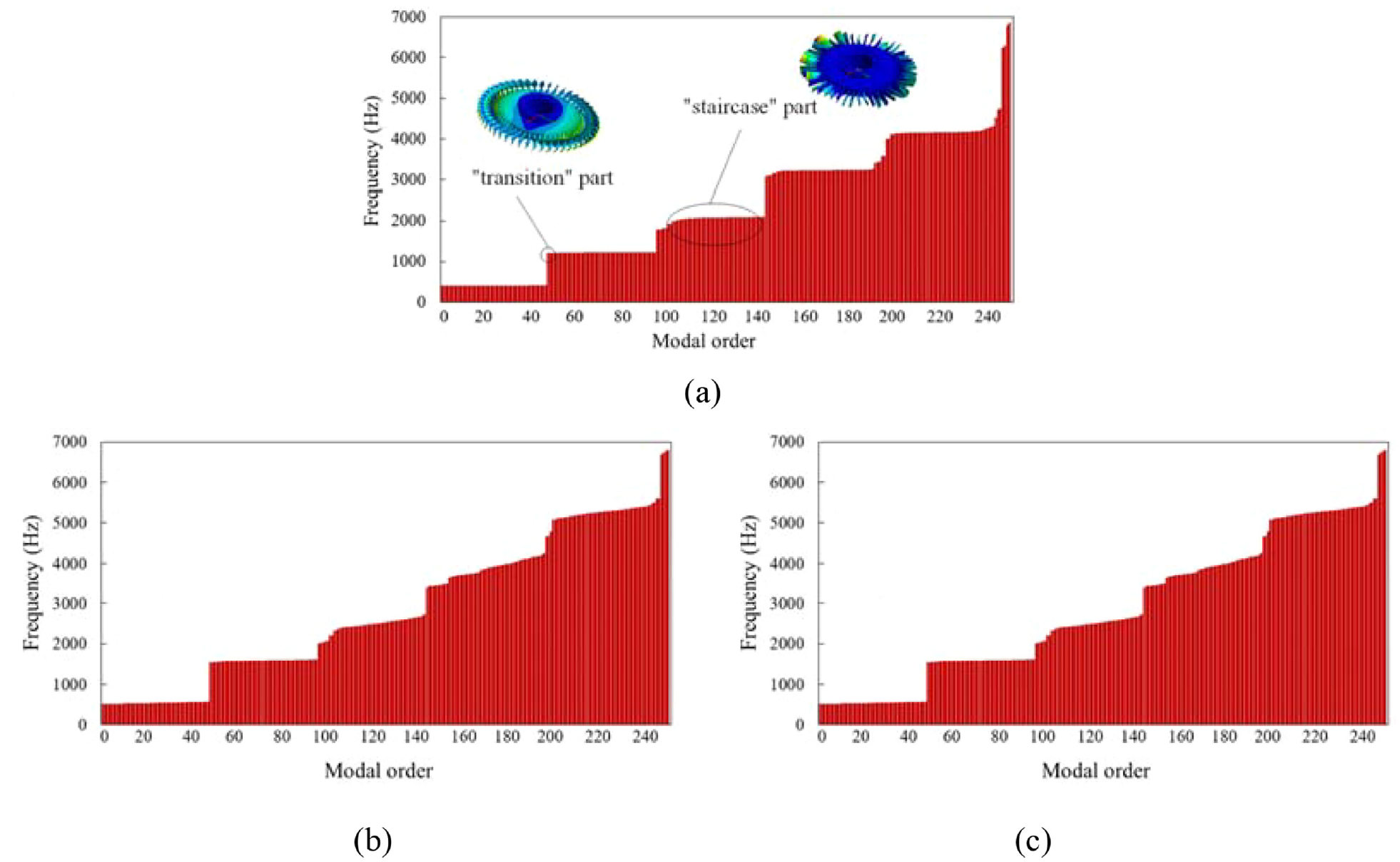
Frequency distribution of calculated modal results: (a) frictional contact, (b) frictionless contact, and (c) bonded contact.

Modal shapes of the TDS with frictional contact.
The first six-order coupled vibration results of the TDS with three contact conditions.


Modal shapes of the TDS with frictionless contact.

Modal shapes of the TDS with bonded contact.
Since the blade and the turbine disk are connected through a tenon-based structure, the TDS modal shape couples with the pitch diameter. The main vibration of the TDS is dominated by the blade’s vibration. Under a specific order, a circle of blades can be divided into several groups, and the same group exhibits bending, torsion, or compound vibration in the same direction. As shown in Figure 4, the second order mode of the TDS is a bending vibration of the one-diameter blade, the third order and fourth order are the three-diameter coupled vibration, the fifth order is a typical four-diameter coupled vibration, and the sixth order presents a second order torsional vibration. Meanwhile, the weak links of the entire TDS are concentrated in the blade structure. As a result, a few blades may be damaged when the resonance occurs.
The calculation results of three FEA models are shown in Figure 7 where the vibration frequency versus the order is plotted. It can be seen that the frequency of the frictionless contact condition is higher than those of the other two models. The frequency difference is greatest in the third order and smallest in the sixth order. At lower modes, the frequency curves on the bonded and frictional contact conditions are very close, but deviations change significantly when the modal order is greater than the fourth order.

Three kinds of FEA models coupled vibration frequency curve.
Experimental modal analysis of the TDS
To validate the calculation results, the EMA was carried out. The scene of the experimental modal test is shown in Figure 8. During the modal test, an accelerometer (353B33, PCB), a data acquisition device (INV3060C, COINV), a hammer (INV9311, COINV), and a computer with DASP MAS software were used. The detailed experimental procedure is as follows:
Arrangement of measuring points: In the experiment, the moving hammer was used to excite the measuring points, that is, the moving hammer hit all measuring points and an accelerometer was fixed for measurement. The turbine disk-blade system is a circumferentially symmetrical structure, so the measuring points were arranged evenly. As shown in Figure 8, the measuring points were evenly arranged in four circles around the axial direction along the radial and circumferential directions. According to the modal shape distribution obtained by FEA, 39 measuring points can meet the EMA requirements. The measuring point 11 was the vibration pickup point, which was used to collect the acceleration response signal, as shown in Figure 8(a). The number of hammer excitation points was 39.
Set up the experimental system: An experimental system was established to test the vibration characteristics of the TDS. Due to the small volume and light weight of the turbine disk-blade system, the hammer excitation method was selected to carry out the EMA. With reference to the FEA calculation results, the sampling frequency of the modal analysis was 0–10 kHz, which was the same as that of the FEA. Therefore a hard hammer head was used to excite the turbine disk-blade system. The stiffer the hammer head, the wider the frequency range of excitation. In this study, a metal hammer head with a force sensor was used. In the experiment, a rigid constraint was imposed on the turbine disk-blade system to simulate the working state, which is the same as FEA.
Signal acquisition: For each hit of the hammer at a measuring point, we will get a set of force spectrum signal and acceleration response signal, using this set of signals can obtain the frequency response function between two measuring points. In this study, the hammer was used to hit 39 measuring points one by one. Each measuring point was hit multiple times, and three groups of valid data (coherence function value > 0.8) of force signal and acceleration response signal at each point are collected.
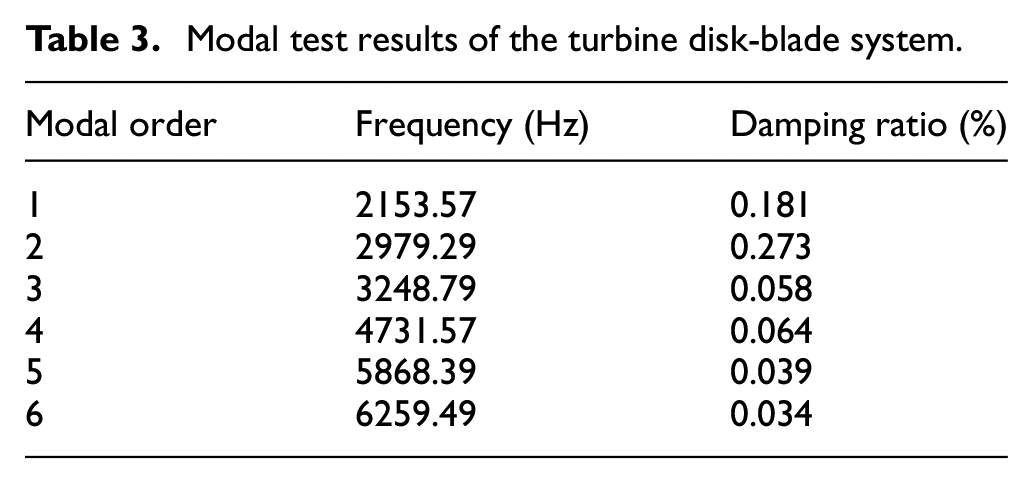
Signal analysis: The ensemble average was performed on the amplitude-frequency data of the frequency response function of all measuring points. The modal frequency, damping ration and modal shape of the TDS were identified by the complex mode single degree of freedom method. The results are shown in Table 3 and Figure 9.

Experimental steup of the modal test system: (a) experimental schematic and (b) experimental steup.
Modal test results of the turbine disk-blade system.

Turbine disk-blade system modal shape diagram.
The modal shape of each modal order is shown in Figure 9. It can be seen that the EMA and FEA results are similar, and both of them show a coupled vibration with the pitch diameter. Taking the fourth-order modal shape as an example, the modal shapes obtained from the three FEA models and the modal shape obtained from the EMA are consistent, and they are all three-section diameter bending vibration. Therefore, they can be regarded as the same order modal shape, and their frequencies can be compared and analyzed. The results of the two methods are compared in Table 4. The modal shapes of the TDS obtained by EMA and FEA are blade vibrations, and the blades are the weak links of the whole system.
Modal analysis results of the turbine disk-blade system.

Table 4 shows the error between the frequencies of each order obtained by the three FEA models and the frequencies obtained by EMA. The reason for the error is that the FEA models were simplified to be undamped, while the TDS itself contains damping. Compared with the other two models, the results of the frictionless contact FEA model have a large error, especially the frequency error of the third modal order is up to 44.9%. Therefore, we can directly abandon the frictionless contact FEA model. For the other two FEA models, we can further analyze the error through the average error and root mean square error to find the most appropriate FEA model for the TDS. Table 5 shows specific error analysis.
The error characteristics of the three kinds of FEA modal frequency.

It can be seen that the results of the frictional contact FEA model are more stable, and the average error and the root mean square error are the smallest, with the average error of 1.42% and the root mean square error of 0.75%. Therefore, the analysis between FEA and EMA results shows that the calculation results of the frictional contact FEA model are most consistent with the actual situation, and the model can be used to calculate the working modes of the TDS at different speeds.
Computational modal analysis of the TDS at different speeds
In the actual operation, the centrifugal load will be generated due to the high-speed rotation of the engine shaft, which causes a significant change in the contact stiffness of the TDS.28,29 Therefore, it is necessary to investigate the vibration frequency and mode shapes of the TDS at different rotation speeds. The relevant research was carried out based on the FEA model. The centrifugal loads can be simulated by applying a revolving speed to the axis of the FEA model. Considering the actual working conditions of the TDS, three speeds were selected, involving a slow speed of 11,000 r/min, a nominal speed of 19,000 r/min, and the maximum speed of 27,000 r/min. The modal analysis results of coupled vibration are listed in Table 6.
The frequency of coupled vibration of the TDS at different rotation speeds.
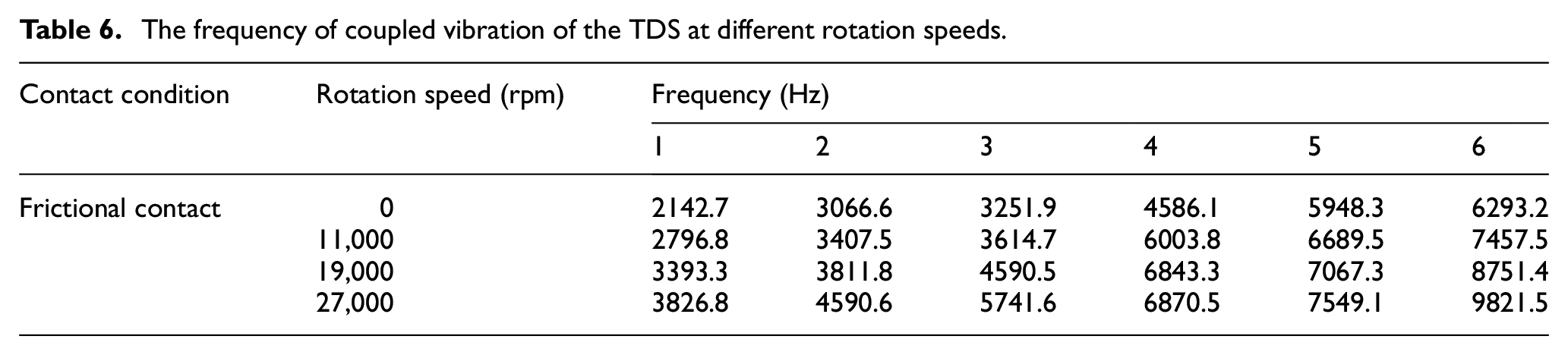
Figure 10 shows the frequencies of the TDS at different speeds. It can be clearly seen that the modal frequencies of each modal order increase with the increase of rotation speed. In addition, the modal shapes of each modal order are the same as those in Figure 4. Therefore, in the subsequent structural optimization, the weak links can be determined according to the modal shapes, and the working frequencies calculated at the TDS working speeds need to be avoided.
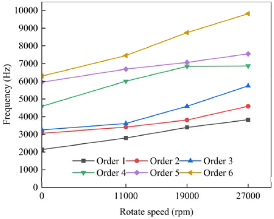
The frequency of the TDS at different rotation speeds.
Conclusion
To simulate the contact condition between the turbine disk and blades of the TDS and to establish the most accurate FEA model, three contact conditions, involving the bonded, frictionless, or frictional were used. The modal characteristics in different FEA models were analyzed and compared with EMA results. The following conclusions were obtained.
All three FEA models can obtain the modal shape diagrams of each modal order of the TDS, but the obtained modal frequencies of each modal order are different due to different contact conditions.
The results of the frictional contact FEA model are in the best agreement with the results of the EMA. Its error is the smallest among the three models. The maximum error of each modal frequency does not exceed 3%, the average error is 1.42%, and the root mean square error is 0.75%. Therefore, the frictional contact FEA model presents the most accurate and reliable results.
When different rotation speeds were applied, the working frequencies of the TDS increased with increasing rotation speed. In the subsequent structural optimization, we can avoid the resonance damage of the system according to the working frequencies of the TDS. It can provide some meaningful help to the structure optimization of the TDS in a future study.
Footnotes
Handling Editor: Chenhui Liang
Declaration of conflicting interests
The author(s) declared no potential conflicts of interest with respect to the research, authorship, and/or publication of this article.
Funding
The author(s) disclosed receipt of the following financial support for the research, authorship, and/or publication of this article: This work was supported by the Natural Science Foundation of Tianjin [grant number 16JCZDJC38600], the Science & Technology Commissioner Program of Tianjin [grant numbers 22YDTPJC00050, 21YDTPJC00660, 20YDTPJC00610], the Science & Technology Development Fund of Tianjin Education Commission for Higher Education [grant number 2020KJ058], and the Tianjin Research Innovation Project for Postgraduate Students [grant number 2021YJSS335, 2021YJSO2S19].