
Abstract
Based on traditional 3-D multi-component NS(Navier-stokes) equations, with chemical reaction Preconditioning method was analyzed and the preconditioning matrix was applied for the pseudo-time derivative term of the equations. Preconditioned AUSM+-up scheme was used for space discretization, with implicit time integration LU-SGS (Lower-Upper Symmetric Gauss-Seidel). These two schemes were combined to develop a unified algorithm for flows at all speeds. In addition, Numerical experiments of flows from low speed to high speed, with and without chemical reaction, were performed in this paper. By comparing the results of simulations with experiments showed the algorithm utilized the imposed preconditioning matrix, obtained better results. It was fairly well demonstrated that the improved methods can be applied efficiently for chemical reacting flow at all speeds.
Introduction
Over the last 20 years, the preconditioning method has been attracting more and more attention for its ability to improve the computational capability of the algorithm of low Mach number compressible flows.1,2 From the prospect of requirement, on the one hand, most high-speed flows contain both compressible and incompressible flows characteristics. One typical case is the flow around the airfoil at a high angle of attack 3 . On the other hand, for low-speed flows, sometimes the dramatic heat exchange at the wall causes the significant change of the density, the compressible effect is nonignorable. Such as the problem of low-speed combustion flow. Thus, for the typical inner flow of the aero-engine, which contains both high and low Mach number flows, and also contains dramatic change of temperature and density at some local low-speed flow parts, it is necessary to develop a unified algorithm that applied to all Mach number 3D flows. However, preconditioning method also has its limitations, 4 (1) it is sensitive to the pressure disturbances; (2) it lacks time precision for steady problems.
Huang introduced a preconditioning method, which using pressure, speed and enthalpy as the original variables.5–7 Combined with finite volume method, he developed a unified CFD (computational fluid dynamics) software. By comparing the results with other renowned software, he proved that the same set of programs can be to calculate compressible and incompressible flow problems without chemical reaction by introducing preconditioning method. Xiao used the preconditioning matrix based on pressure, speed, and temperature as the original variables, combined with the finite difference method to numerically simulate the rotor hovering flow, and verified the effectiveness of the preconditioning method through comparing with experiments 6 . Pan et al. 8 constructed a preconditioning matrix based on the original variables of pressure, velocity, and enthalpy. Using the finite difference method, combined with the LU-SGS implicit method and the 2D compressible non-equilibrium control equation was coupled to solve the chemical reaction shear layer and the shock wave ignition. He demonstrated the feasibility of the preconditioning method. Liu et al. 9 simulated the 2D all-speed reaction flows, which proved computational capability of preconditioning method for solving complex flows by setting pressure, speed, and enthalpy as the original variables, combined AUSM+ format.
Based on the discussions above, the current preconditioning methods are mainly aimed at 2D/3D non-Chemical reacting flows or 2D Chemical reaction flows at all speeds, and there is still a lack of in-depth research on 3D all speed Chemically reacting flows. Based on the AHL3D large-scale parallel computational program and preconditioning method, we developed a set of computational program.10,11 The extant program is based on the 3D multi-component NS governing equation, and is capable of simulating the 2D/3D, steady/unsteady, ideal gas, or chemical non-equilibrium high speed flows. It has a variety of turbulence models and has been studied extensively for scramjet with satisfactory results through comparing with the experiments.12–14 It was widely considered to be reliable. However, as the Mach gradually decreases and approaches zero, the compressibility of the fluid becomes smaller and smaller, and gradually presents a trend of incompressibility. And then the governing equations of this program occur stiff phenomena and the problem of low speed flows cannot be solved. In order to expand the function of the program and solve the Chemically reacting flows at all-speed. A self-derived preconditioning matrix based on original variables of pressure, velocity and temperature, combined with the implicit time integration LU-SGS and splitting scheme AUSM+-up are was applied to the pseudo-time term of the control equation. 15 Meanwhile, preconditioning method has no effect on steady problems, but it lacks time accuracy when dealing with unsteady problem, so dual-time-stepping method was adopted. The sensitivity of preconditioning method to pressure disturbance can be overcome by putting the preconditioning system in multiple time frames. In this paper, supersonic combustor and Sydney bluff body combustion flows were simulated. The results were compared with the literature. The results demonstrate that, with the utilization of the preconditioning matrix, the original program can get better results when dealing with low speed flows, without losing its accuracy in solving high speed flows fields. This gives significant support to the unified algorithm that based on the development of 3D multi-component NS equation.
Physical model and computing method
Governing equation
The governing equation is a 3D multi-component NS equation based on conservative variables. The pseudo-time derivative term is changed to the original variable and multiplied by the preconditioning matrix

Where,

Here, e is the internal thermodynamic energy. 18
Equation (1) indicates that, after preconditioning, this new governing equation is not comparable with the original NS equations. However, to steady problems, when the time term is close to zero, the influence of preconditioning matrix is vanished and equation (1) is comparable with the NS equation. To unsteady problems, dual time-stepping method is adopted.
The selection of the preconditioning matrix is pivotal to the convergence of the preconditioning equation. So, the design and principle of the preconditioning matrix are discussed in detail in the literature. 19 Based on Weiss and Ding’s work, a 3D chemical non-equilibrium preconditioning matrix based pressure, velocity, and temperature as the original variables is independently derived, The form can be presented as

Where,
Total preconditioning method;
Local preconditioning method;
Local preconditioning method with total truncation;
Local preconditioning method with local truncation;
Local maximum value preconditioning method.
It got better results through using the local preconditioning method. 4 Therefore, the local preconditioning method was adopted in this paper.

Here,
Eigenvalue of the preconditioning matrix
Weiss and Smith
20
gave the eigenvalue in the

In the governing equation, K is the condition number, which is the ratio of the largest eigenvalue to the smallest eigenvalue and indicates the stiffness of the equation. From Table 1 It can be seen that the Mach number is close to 0 and 1, the condition number is close to infinite, thus the original equation is insolvable unless we introduce the preconditioning method.
Condition numbers.

Litton et al.
21
gave the eigenvalue in the

here, S is the area of the grid surface.
With high Mach number,

This makes sure that the eigenvalues in (5) are at the same order of magnitude and improves the rigidness of the equation, thus realizes the applicability to low speed flows field. At the same time, this also realized the smooth transformation from low speed preconditioning to high speed preconditioning, avoids the affection of computational efficiency of high Mach flows because of calculating the inverse of the preconditioning matrix.
Preconditioning has little effect on the viscid eigenvalue, in order to save the computing time, the viscid eigenvalue is the same as that of without preconditioning in this study.
Chemically reacting algorithm
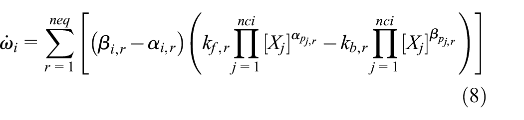
The flows timescales and the Chemically reacting timescales are large difference from each other in the low speed combustion, and the source term of chemical reaction is strongly nonlinear. These bring serious stiffness to the solution of the equations. Chemical reaction needs to be solved separately by decoupling, The reaction source term is substituted into the component transport equation, and then it is coupled with other equations. Its equation can be expressed as

The solution of the chemical reaction involves the solution of the above stiff ordinary differential equation. A steady state approximation method is used to solve the stiff equation in this paper. This method is specifically designed for the calculation of chemical reaction and it is widely used in the calculation of chemical reaction.22,23
Here,


The molar concentration of the component xi is replaced by yi.
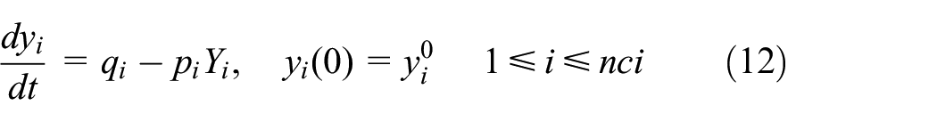
If p, q is a constant (minus the subscript), then the expression (11) has an exact solution

Referring to the α-QSS method developed by Mott et al., 24 the formula (12) can be rewritten as


Results and discussion
Numerical simulation of scramjet
In order to test the inheritance of the computing capability of preconditioning algorithm to 3D supersonic Chemically reacting flows, this study investigated the numerical simulation of the ethylene-fueled combustion scramjet. The computational model is the single-grooved combustor model. 12 It has four expansive parts, the area of its inlet cross-section is 50 mm × 100 mm, and its total length is 1700 mm. It can be seen from Figure 1 The three fuel injection points are set at the front and back of the external part of the groove, and in the groove, with mass flows rate 1:3:2. The turbulence model is k-ε model, the combustion model is finite-rate model, and the ethylene chemical kinetic model is Mawid and Sekar’s three-step chemical kinetic model. 25 High temperature oil method is used to trigger the fire, so the temperature of the ethylene is high at the beginning of the injection, and cools down to the average oil temperature after a while. This study takes the high altitude incoming flows to be of Mach number 4, total temperature 937 K, and total pressure 0.8 MPa. The corresponding inflows condition at the separation section of the scramjet is listed in Table 2. The incoming air is set to be polluted air, and its mole ratio of nitrogen, oxygen, and water is set to be 69:21:10 12 .

Schematic of scramjet combustor.
Inflows conditions.

The numerical and experimental results of the wall pressure of the non-chemical reaction, both with and without preconditioning had been shown in Figure 2.This experiment was conducted using the 3 kg/s pulse tunnel in the China aerodynamics research and development center (CARDC). It can be seen from Figure 3, the two results are nearly identical, thus the simulation of the 3D non-Chemical reacting flow field is regarded as reliable. The eigenvalue is indeed reduced to its original form, closing the preconditioning does not affect the results. The schlieren figure of the groove is given in Figure 4 of non-reaction 26 . The stress contour of the groove is given in Figure 5 of numerical simulation in the same condition as the experiment. From these two figures, we can see that, the wave structure of the flows given by numerical simulation is almost same as the schlieren figure given by experiment.

Wall pressure in non-reacting flows.

Photo of impulse combustion wind tunnel.

Schlieren figure of the cavity field.

Pressure contour map of the cavity field.
To test the influence of chemical reaction, the wall pressure of the 3D combustion flows field both simulation and experiment had been given in Figure 6 with and without preconditioning. It can be seen that numerical and experimental results are largely coincide, which further verifies the reliability of this program in dealing with the combustion flows. It also verified the regression of the preconditioning matrix in simulation of the supersonic combustion flows field. The contour of Mach number and mass fraction of the 3D combustion flow field are given in Figures 7 and 8 respectively. It can be see that, the Mach number at most parts of the combustor is bigger than 1 and the combustion is basically in a state of supersonic combustion in Figure 7. From Figure 8 we can see that, because of the influence of the oiling, combustion occurs only at the upper parts of the combustor. This indicates the inefficient use of the runner. In the future, oil injection combustion on the lower wall can be considered to further improve engine performance.

Wall pressure in reacting flows.
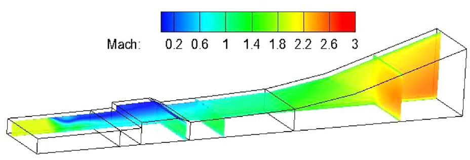
Mach number contour in reacting flows.
CO2 mass fraction contour in reacting flows.
Through the numerical simulation of the supersonic flows, we can get that the eigenvalue of the preconditioning equation is reduced to its original form. The preconditioning program is correct and efficient in dealing with 3D supersonic flow.
Numerical simulation of Sydney bluff body
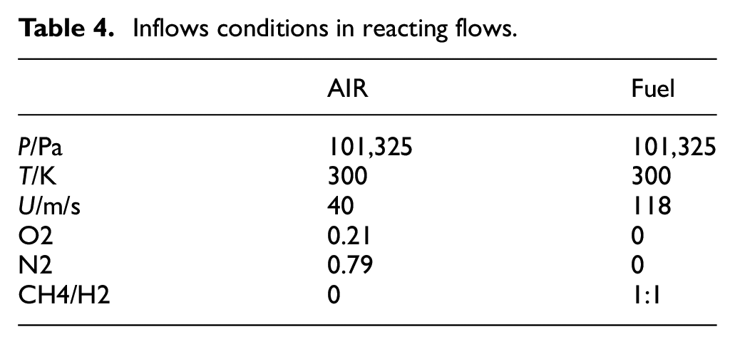
In order to investigate the reliability of the added preconditioning program for the calculation of 3D low-speed flows, including non-chemical reaction and combustion for the Sydney bluff body. 27 The Sydney bluff body is one of the standard series of flames in the International Symposium on Measurement and Calculation of Turbulent Diffusion Flames. 28 The schematic diagram of the bluff body structure is shown in Figure 9. The specific experimental conditions of the flows without chemical reaction are showed in Table 3 and the specific experimental conditions of the combustion flows are showed in Table 4. In order to reduce the error caused by the outlet boundary conditions on the flows field, the axial length of the grid is 600 mm, and the reaction mechanism involving five elementary reaction was used. 29
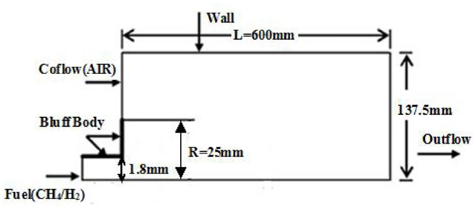
Sketch of bluff body.
Inflows conditions in non-reacting flows.

Inflows conditions in reacting flows.
The distribution of the mixture-fraction along the x-direction of each cross-section and the streamline of symmetric of non-chemical reaction are given respectively in Figures 10 and 11. Mixing fraction is a very important physical quantity in non-premixed calculations. From it can be seen from the streamline diagram that the length of the recirculation zone is approximately x = 50 mm. It can be seen that as the axial distance increases, the mixing fraction begins to decrease, and the decrease is very obvious at 55 mm, that is behind the recirculation zone and the most significant mixing occurs between the fuel jet and the inner vortex from Figure 10.To gradually diffuse outward downstream, the mixing of the outer vortex and the air wake is the strongest, and the mixing fraction is in good agreement with the experiment, only at x = 30.5 mm which is the downstream of the recirculation zone. The value is slightly deviated near the axis. It can be seen that the decay of the mixture fraction downstream of the recirculation zone is slower than the experimental. However, the deviation is very small. The peak value of each section better reflects the position of the mixed layer (0–25 mm), and the size and position of the peak value are relatively consistent. The simulation of non-Chemically reaction flow indicates that it is efficient in calculating the diffusion of 3D low speed multi-component turbulence flows after applying the preconditioning program, which overcomes the shortcomings of the original program in dealing with the problem of low-speed flow.
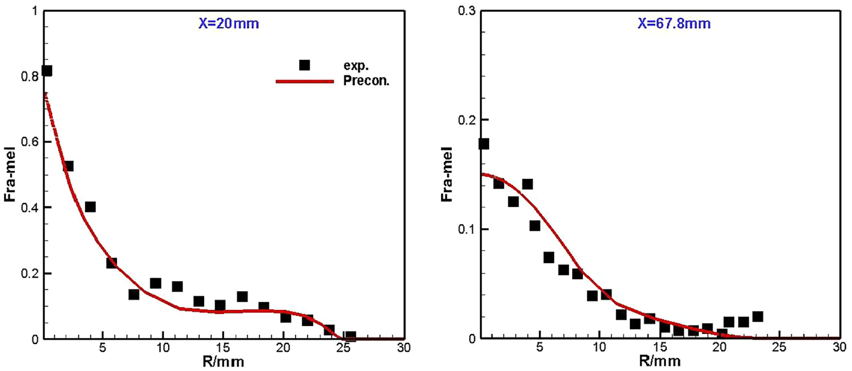
Radial profiles of Fra_mel on x-planes.

Streamlines at symmetry plane in non-reacting flows.
The radial distribution of each cross-section of the temperature of the combustion flows in the x-direction is showed in Figure 12. It shows that the preconditioning program can not only simulate the non-chemical reacting flow with circulation reflux, but also accurately predict the temperature of the low-speed combustion flows. The maximum values of the temperature distribution curve adequately reflect the width of the flame and on the air wake side of the outer vortex, which is about 0–25 mm long. The change in the range of the high temperature zone also fully shows that width of the flame is from the recirculation zone to the exit. The process of changing from width to narrower and finally becoming stable. The temperature cloud picture in Figure 13 also shows this characteristic of change well.

Radial profiles of temperature on x-planes.

Iso-surface of temperature.
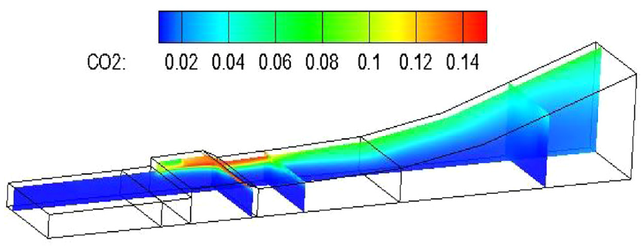
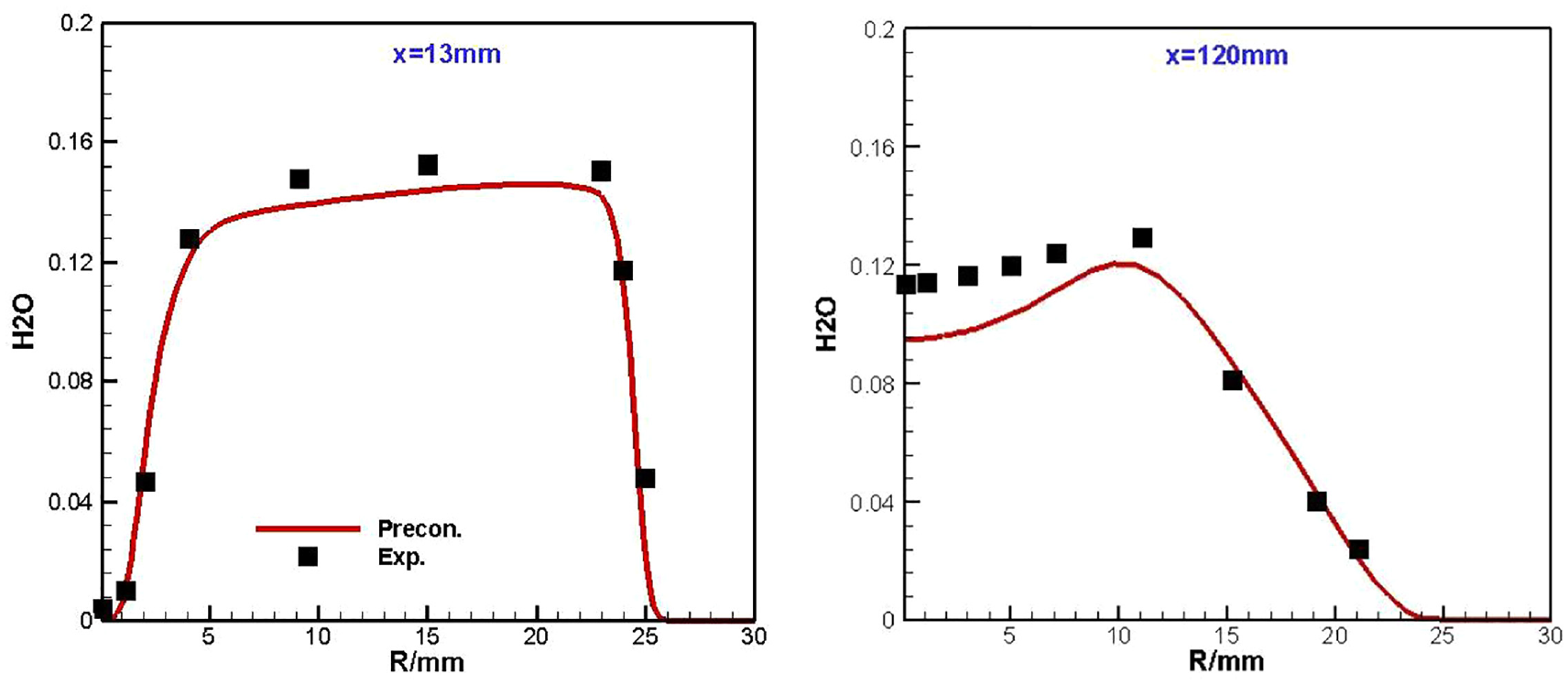
Figure 14 shows the distribution of CO2 mass fraction, which is the main product of combustion. It demonstrates that distribution of CO2 is basically consistent with the average temperature. At the same time, it can be seen that distribution of CO2 of the cross-section of x = 13 mm, that is, the front section of the recirculation zone, the longitudinal change trend of this section is basically the same as the experimental, but the rear end of the recirculation zone is near the axis which the value of is slightly deviated, which is similar to the flows without chemical reaction, because the decay of the mixing fraction in the recirculation zone is slower than the experimental. After passing through the recirculation zone, the diffusion is accelerated, so the CO2 mass fraction is higher than the test value. Another major combustion product, H2O, is shown in Figure 15, with similar results.
Radial profiles of mass fraction of CO2 on x-planes.
Radial profiles of mass fraction of H2O on x-planes.
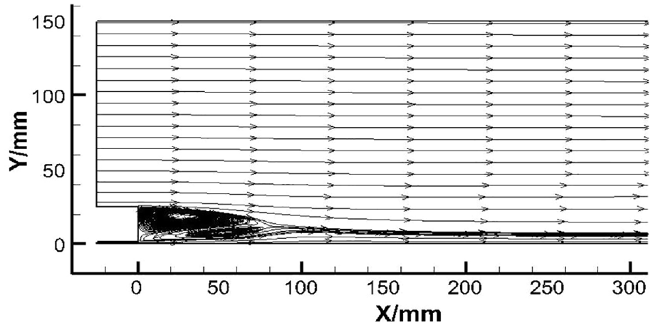
The streamlines of the symmetry plane is showed in Figure 16, It can be seen from the streamline that compared with the flow without chemical reaction, the flows behind the bluff body still presents a double vortex structure in the combustion state, forming a stable recirculation zone composed of vortices. The length of the recirculation zone calculated in this paper is about 77 mm, which is close to the experimental. 17 It can be seen from the temperature that the recirculation zone behind the bluff body is a high temperature zone. At the end and neck area of the recirculation zone, as the temperature decreases significantly, partial flameout occurs.

Streamlines at symmetry plane in reacting flows.
It can be seen from the numerical simulation of the 3D Sydney symmetry bluff body flows field based on the basis of the original calculation transcendent program that embeds the preconditioning matrix, and overcomes the limitations of the preconditioning itself by using the implicit time advance method. This program gets better results in calculating the low speed non-Chemically reacting flows and combustion flows, while maintaining its precision and correctness. The function expansion of using the traditional compressible flows theory to solve the Chemically reacting flows at the all speed Chemically reacting flows.
Conclusions
Based on the consideration of the 3D flows effect, the with chemical preconditioning method is analyzed and the self-developed large-scale parallel program AHL3D was embedded a self-derived low speed preconditioning matrix on the pseudo-time term idea:
It was adopted the high-order AUSM+-up split format of non-stick flux. The numerical simulation of the combustor of the scramjet verifies the consistency of the non-precondition results under high speed conditions, which fully proves that the correctness of the program calculation of high speed flows is not destroyed after the preconditioning matrix is added.
In order to further verify that the original program overcomes the limitations of preconditioning itself after applying the preconditioning matrix, and realizes the calculation of 3D low speed flows field, numerical simulation is carried out on the classic example of 3D Sydney bluff body structure, and temperature of the given flows, vortex structure, recirculation zone length, and the distribution of component concentration are basically in line with the experimental.
It was considered 3D flows characteristics and applied the preconditioning matrix on the basis of the original program, further improves the calculation program, increases the versatility of the program, and realizes the effective solution in the range of low speed to high speed.
Footnotes
Handling Editor: Chenhui Liang
Declaration of conflicting interests
The author(s) declared no potential conflicts of interest with respect to the research, authorship, and/or publication of this article.
Funding
The author(s) received no financial support for the research, authorship, and/or publication of this article.